CN210024186U - Double-station welding device for supermarket shelf stand columns - Google Patents
Double-station welding device for supermarket shelf stand columns Download PDFInfo
- Publication number
- CN210024186U CN210024186U CN201920467977.2U CN201920467977U CN210024186U CN 210024186 U CN210024186 U CN 210024186U CN 201920467977 U CN201920467977 U CN 201920467977U CN 210024186 U CN210024186 U CN 210024186U
- Authority
- CN
- China
- Prior art keywords
- frame
- guide rail
- double
- cylinders
- station
- Prior art date
- Legal status (The legal status is an assumption and is not a legal conclusion. Google has not performed a legal analysis and makes no representation as to the accuracy of the status listed.)
- Expired - Fee Related
Links
Images


Abstract
The utility model relates to a welding device in the field of storage, in particular to a double-station welding device for supermarket shelf uprights, which comprises a frame, two moving platforms positioned at the top of the frame, and two stations which are symmetrically arranged in the left and right directions, wherein each station comprises an upright frame and two cross rod frames respectively arranged at the left side and the right side of the upright frame; the two groups of moving platforms are respectively positioned at the front side and the rear side of the station, and each moving platform is provided with a moving gun rack with a welding gun. The device can effectively fix the parts of the goods shelf, reduce the number of workers and the workload, operate the welding gun to weld the required welding places, save time due to double-station design and improve the working efficiency.
Description
Technical Field
The utility model relates to a welding set in storage field, concretely relates to be applicable to supermarket stand welded duplex position welding set.
Background
At present, the stand columns in the supermarket need to be clamped, fixed and then manually welded one by one, the production efficiency is low, the working environment is poor, the welding quality is difficult to guarantee, even gaps can be formed in the stand column welding, so that the whole stand column is scrapped, and great economic loss is caused.
The Chinese patent with publication number CN103990746A discloses a square upright welding forming machine production line, which has the advantages that a shearing device realizes tracking shearing, so that the production process does not need to be stopped for waiting for shearing, the aim of continuous production is fulfilled, and the production efficiency is improved; the disadvantage is that no welding step and method for column parts is provided. Publication No.: CN104741744A discloses a column welding for a heavy and large Q420B steel construction steel structure, which has the advantages of adopting an automatic submerged arc welding multi-layer multi-pass welding process, having high welding automation degree, few cold cracks in a welding seam structure, high welding quality, low labor intensity of welding operation, less welding investment and greatly reduced welding man-hour, thereby leading the welding process to better meet the requirement of building the heavy and large construction steel structure on the whole; the method has the defect that when nondestructive detection is carried out, corresponding detection standards do not exist, and two methods of machine vision and ultrasonic detection are fused. The Chinese patent application with the publication number of CN106624540A discloses an upright post welding device, which has the advantages that two groups of clamping structures on a roll-over stand are respectively switched between a welding station and a material replacing station, so that the two groups of clamping structures are circularly and continuously matched with an operating arm to work, and the operating arm is ensured to carry out continuous welding operation; the defect is that the processing efficiency is influenced by reloading materials on the clamping mechanism.
The supermarket upright post welding device is a production device integrating welding, forming and production lines, and welding quality and defects need to be effectively processed in time in the forming process. The double-station and multi-station operation ensures smooth welding process, facilitates product molding and reduces processing time. Aiming at the problems, compared with the prior art, the double-station welding device for the supermarket shelf stand columns is designed.
SUMMERY OF THE UTILITY MODEL
The utility model aims at providing a be applicable to supermarket stand welded duplex position welding set, the utility model discloses there are better efficiency and precision to guarantee, but the extensive welding of equipment such as goods shelves of being applied to.
The utility model aims at realizing through the following technical scheme:
a double-station welding device for supermarket shelf columns is characterized by comprising a rack, two moving platforms positioned at the top of the rack, and two stations which are symmetrically arranged left and right, wherein each station comprises a column frame and two cross rod frames respectively arranged on the left side and the right side of the column frame; the two groups of moving platforms are respectively positioned at the front side and the rear side of the station, and each moving platform is provided with a moving gun rack with a welding gun;
the rack is respectively provided with racks at positions corresponding to the mobile platform, the mobile platform is provided with a first servo motor, and the first servo motor is meshed with the corresponding racks through a gear to drive the corresponding mobile platform to move left and right between two stations of the rack.
Preferably, each moving platform is provided with two second servo motors and two moving gun frames, output shafts of the two second servo motors are arranged oppositely, and the end parts of the output shafts are respectively connected with a second screw rod; the bottoms of the two movable gun racks are respectively in threaded connection with the two second screw rods and are in horizontal sliding connection with the corresponding movable platforms through the first guide rail group.
Preferably, a third screw rod, a first guide rail platform and a third servo motor are vertically arranged on the frame body of each movable gun frame, an output shaft of the third servo motor is connected with the third screw rod, and the first guide rail platform is in threaded connection with the third screw rod and is in up-and-down sliding connection with the frame body of the movable gun frame through a second guide rail group;
the first guide rail platform is provided with a fourth screw rod, a second guide rail platform and a fourth servo motor, and the fourth screw rod is horizontally arranged along the front-back direction and is in driving connection with the fourth servo motor; the second guide rail platform is in threaded connection with the fourth screw rod and is in front-back horizontal sliding connection with the first guide rail platform through the third guide rail group.
Preferably, each cross rod frame comprises a bottom plate fixedly connected with the rack, a cross rod frame main body, a supporting strip for placing parts, a supporting block and a first air cylinder; the bottom of the cross rod frame main body is horizontally connected with the bottom plate in a left-right sliding mode through a combined guide rail, a vertical strip-shaped hole is formed in the middle of the cross rod frame main body, and the supporting strip is connected with the cross rod frame main body through a bolt and the vertical strip-shaped hole; the support block and the first air cylinder are arranged on the upper portion of the cross rod frame main body, and an output shaft of the first air cylinder points to the support block and is matched with the support block to clamp a part.
Preferably, the combined guide rail comprises a base with a cavity, a sliding plate arranged at the top of the base, an adjusting bolt and a limiting plate; the base is fixedly connected with the bottom plate, a sliding groove is horizontally arranged at the top of the cavity wall of the base, the limiting plate is arranged in the cavity of the base, a convex block matched with the sliding groove is arranged at the bottom of the sliding plate, the bottom of the cross rod main body is fixedly connected with the sliding plate, the sliding plate is connected with the base in a left-right horizontal sliding mode through the convex block and the sliding groove, and the adjusting bolt sequentially penetrates through the sliding plate, the sliding groove and the limiting plate in a threaded connection.
Preferably, a magnet for adsorbing the part is arranged at the supporting strip.
Preferably, each upright post frame comprises an upright post, an upper transverse plate, a lower transverse plate and a second air cylinder which are vertically fixed on the frame, and the upper transverse plate and the lower transverse plate are arranged in parallel and are respectively and vertically fixed at the middle position of the upright post; the two ends of the upper transverse plate are respectively provided with a third cylinder, and output shafts of the two third cylinders are vertically downward;
two side supporting plates and a middle supporting plate for placing parts are arranged on the lower transverse plate, and the two side supporting plates correspond to the two third air cylinders respectively; the second cylinders are rotary telescopic cylinders, the number of the second cylinders is a plurality of, the second cylinders are distributed on the upper portion of the stand column, the output shafts of the second cylinders are perpendicular to the stand column, and the end portions of the output shafts are provided with positioning blocks for fixing parts.
Preferably, the two sides of the upper transverse plate are respectively provided with an upper transverse strip-shaped hole, and the cylinder frames of the two third cylinders are respectively connected with the upper transverse plate through bolts and the upper transverse strip-shaped holes.
Preferably, lower transverse strip-shaped holes are formed in two sides of the lower transverse plate respectively, and the two side supporting plates are connected with the lower transverse plate through bolts and the lower transverse strip-shaped holes respectively.
Preferably, the bottom of the upright post is provided with a reinforcing rib at the joint with the frame.
Compared with the prior art, the utility model discloses following beneficial effect has:
firstly, a movable platform, a cross bar frame and a column frame are arranged at the upper part of a machine frame, the movable platform is connected with the machine frame in an embedded mode through a guide rail, and the guide rail is connected with the machine frame through a screw; the cross bar frame and the upright post frame are respectively connected with the frame through screws; the two cross rod frames are positioned on two sides of the upright post frame and are symmetrically distributed; the upper part of the moving platform is provided with a moving gun rack, and the moving gun rack is connected with the moving platform in an embedded manner through a guide rail; the screw rod on the mobile platform adjusts the position of the mobile gun rack; and the upper part of the movable gun rack is provided with a welding gun, and the welding gun is used for welding the goods shelf parts clamped by the upright post rack and the cross rod rack. This device can effectively fix a goods shelves spare part, reduces workman's quantity and work load, controls welder and welds the place that needs the welding.
Secondly, the double-station design is favorable for improving the production efficiency, when the goods shelf at the first station is welded, an operator places the goods shelf parts on the second station, opens the air cylinder to clamp and position, and after the goods shelf at the first station is welded, the operation controller controls the servo motor to move the welding gun to the second station and then weld. Therefore, time is saved, and working efficiency is improved.
Drawings
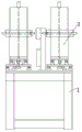
FIG. 1 is a schematic view of the overall assembly of the present invention;
FIG. 2 is a schematic top view of FIG. 1;
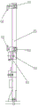
FIG. 3 is a side view of FIG. 1;
fig. 4 is a schematic view of the mobile platform of the present invention;
FIG. 5 is a side view of FIG. 4;
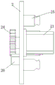
FIG. 6 is a schematic view of the engagement and connection between the rack and the pinion in the mobile platform of the present invention;
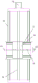
FIG. 7 is a schematic view of the movable gun rack of the present invention;
FIG. 8 is a side view of FIG. 7;
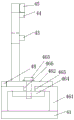
FIG. 9 is a schematic view of the cross bar frame of the present invention;
FIG. 10 is a side view of FIG. 9;
fig. 11 is a schematic view of the column frame of the present invention;
FIG. 12 is a side view of FIG. 11;
FIG. 13 is a schematic structural view of a supermarket column in an embodiment of the present invention;
FIG. 14 is an enlarged view of a portion of FIG. 1;
in the figure: the device comprises a rack 1, a moving platform 2, a moving gun rack 3, a cross bar rack 4, a column rack 5, a first servo motor 21, a second servo motor 22, a second screw rod 23, a gear 24, a first guide rail group 25, a rack 26, a third servo motor 31, a second guide rail group 32, a first guide rail platform 33, a third screw rod 34, a third guide rail group 35, a second guide rail platform 36, a fourth servo motor 37, a fourth screw rod 38, a bottom plate 41, a cross bar rack main body 42, a supporting bar 43, a supporting block 44, a first air cylinder 45, a combined guide rail 46, a vertical strip-shaped hole 47, a blocking bar 48, a base 461, a sliding plate 462, an adjusting bolt 463, a limiting plate 464, a sliding groove 465, a convex block, an upright post 51, an upper cross plate 52, a lower cross plate 53, a second air cylinder 54, a third air cylinder 55, a side supporting plate 56, a middle supporting plate 57, a positioning block 58, a reinforcing rib 59, an upper strip-shaped hole 521, a, A cross bar 7, a rib plate 8 and a vertical rod 9.
Detailed Description
The invention will be further explained with reference to the drawings and the detailed description below:
as shown in fig. 1-3, the double-station welding device for the supermarket shelf upright posts comprises a frame 1, a moving platform 2, a moving gun rack 3, a cross bar rack 4, an upright post rack 5 and the like. The upper part of the rack is provided with a mobile platform 2, a cross rod frame 4 and a stand column frame 5, the mobile platform 2 is connected with the rack 1 in an embedded manner through a guide rail, and the guide rail is connected with the rack through a screw; the cross bar frame 4 and the upright post frame 5 are respectively connected with the frame 1 through screws; the two cross bar frames 4 are positioned at two sides of the upright post frame 5 and are symmetrically distributed.
As shown in fig. 4-6, racks 26 are respectively disposed at positions of the rack 1 corresponding to the moving platforms 2, the moving platforms are provided with first servo motors 21, and the first servo motors are engaged with the corresponding racks through gears 24 to drive the corresponding moving platforms to move left and right between two stations of the rack.
Two second servo motors 22 and two movable gun racks 3 are arranged on each movable platform, output shafts of the two second servo motors are oppositely arranged, and the end parts of the output shafts are respectively connected with a second screw rod 23; the bottoms of the two movable gun racks are respectively in threaded connection with the two second screw rods, and are horizontally and slidably connected with the corresponding movable platforms left and right through the first guide rail group 25, and the screw rods are driven to rotate by driving the second servo motors, so that the corresponding movable gun racks are driven to horizontally move left and right.
As shown in fig. 7-8, a third screw 34, a first guide rail platform 33, and a third servo motor 31 are vertically disposed on the frame body of each movable gun rack, an output shaft of the third servo motor is connected to the third screw, the first guide rail platform is in threaded connection with the third screw, and is connected to the frame body of the movable gun rack in a vertically sliding manner through a second guide rail group 32. A fourth screw rod 38, a second guide rail platform 36 and a fourth servo motor 37 are arranged on the first guide rail platform, and the fourth screw rod is horizontally arranged along the front-back direction and is in driving connection with the fourth servo motor; the second guide rail platform is in threaded connection with the fourth screw rod and is in front-back horizontal sliding connection with the first guide rail platform through a third guide rail group 35. The third servo motor is driven to drive the welding gun to move up and down, and the fourth servo motor is driven to drive the welding gun to move back and forth.
As shown in fig. 9-10, each crossbar includes a bottom plate 41 fixedly connected to the frame, a crossbar main body 42, a bar 43 for placing a part (the supporting foot 6 in fig. 13), a supporting block 44, and a first cylinder 45. The bottom of the cross rod frame main body is horizontally connected with the bottom plate in a left-right sliding mode through a combined guide rail 46, a vertical strip-shaped hole 47 is formed in the middle of the cross rod frame main body, and the supporting strip is connected with the cross rod frame main body through a bolt and the vertical strip-shaped hole; the support block and the first cylinder are arranged on the upper portion of the cross rod frame main body, and an output shaft of the first cylinder points to the support block and is matched with the support block to clamp a part. The supporting legs 6 are vertically placed at the supporting strips, the bottoms of the supporting legs are magnetically adsorbed on the supporting strips, the tops of the supporting legs are clamped and fixed by the first air cylinders and the supporting blocks, the supporting strips move up and down in the vertical strip-shaped holes to be adjusted by screwing bolts, and the position of the cross bar frame and the position of the upright post frame are appropriate.
The combined guide rail comprises a base 461 with a cavity, a sliding plate 462 arranged at the top of the base, an adjusting bolt 463 and a limiting plate 464; base and bottom plate fixed connection, the cavity chamber wall top level of base is equipped with spout 465, and the base cavity is arranged in to the limiting plate, the slide bottom be equipped with spout assorted lug 466, crossbar lever main part bottom fixed connection in slide, horizontal sliding connection about the slide passes through lug, spout and base, adjusting bolt passes slide, spout and limiting plate threaded connection in proper order. The side edge of the top of the base is provided with a barrier strip 48 which ensures the smooth sliding of the sliding plate. The adjusting bolt is screwed, the sliding block is horizontally moved left and right in the sliding groove, the transverse rod frame main body is horizontally moved left and right to be adjusted, and the transverse rod frame and the upright post frame are ensured to be proper in position.
As shown in fig. 11 to 12, each of the post frames includes a post 51 vertically fixed to the frame, an upper cross plate 52, a lower cross plate 53, and a second cylinder 54, the upper cross plate and the lower cross plate are disposed in parallel and vertically fixed to the middle of the post, respectively. The two ends of the upper transverse plate are respectively provided with a third cylinder 55, and the output shafts of the two third cylinders are vertically downward; two sides of the upper transverse plate are respectively provided with an upper transverse strip-shaped hole 521, and the cylinder frames of the two third cylinders are respectively connected with the upper transverse plate through bolts and the upper transverse strip-shaped holes. Through screwing the bolt, the left and right positions of the upper transverse plate of the third cylinder can be adjusted as required.
Two side supporting plates 56 and a middle supporting plate 57 for placing parts are arranged on the lower transverse plate, and the two side supporting plates correspond to the two third air cylinders respectively; the second cylinders are rotary telescopic cylinders, the number of the second cylinders is a plurality of, the second cylinders are distributed on the upper portion of the stand column, the output shafts of the second cylinders are perpendicular to the stand column, and the end portions of the second cylinders are provided with positioning blocks 58 for fixing parts. Two sides of the lower transverse plate are respectively provided with a lower transverse strip-shaped hole 531, the two side supporting plates are respectively connected with the lower transverse plate through bolts and the lower transverse strip-shaped holes, and the left and right positions of the two side supporting plates on the lower transverse plate can be adjusted as required by screwing the bolts. Two side layer boards are used for placing two horizontal poles 7 (and gusset 8 respectively, and side layer board top edge is equipped with the baffle that prevents the gusset landing), and layer board department in the middle of arranging in the bottom of pole setting 9, rotatory telescopic cylinder is rotatory to be stretched out the locating piece, makes its perpendicular to pole setting, and then the shrink to with pole setting upper portion fixed clamp tightly.
A double-station welding device for supermarket shelf columns comprises the following working procedures:
firstly, fixing shelf parts (supporting legs) 6 similar to those in fig. 13 on a cross bar frame 4, fixing shelf parts (cross bars) 7 on two side supporting plates of a vertical column frame 5, placing parts (rib plates) 8 at the tops of the cross bars (output shafts of two third cylinders press the parts 8 downwards to be attached to the parts 7), fixing the bottoms of the parts (vertical bars) 9 on a middle supporting plate, fixing the upper parts of the parts (vertical bars) by positioning blocks, and respectively using the cylinders at the positions to perform fixed clamping;
then, starting a first servo motor to enable the movable platform to move to the position of the first station, finely adjusting the movable gun frame to enable the welding guns to reach the working positions, starting a power supply, enabling the four welding guns to work simultaneously, and welding according to a set working mode;
meanwhile, a second station operator fixes parts to be welded on a second station, and after the welding of the first station is completed, the mobile platform moves to the second station to weld the fixedly clamped parts;
and finally, circulating the operations, wherein the operator only needs to fix the parts on the upright post frame and the cross rod frame and take down the finished product.
The utility model discloses can effectively fix a goods shelves spare part, reduce workman's quantity and work load, control welder and weld required welded place. The double-station design is favorable for improving the production efficiency, when the first station shelf is welded, an operator places shelf parts on the second station, opens the air cylinder to clamp and position, and after the shelf at the first station is welded, the operation controller controls the servo motor to move the welding gun to the second station and then weld. Therefore, time is saved, and the working efficiency is improved.
Claims (10)
1. A double-station welding device for supermarket shelf columns is characterized by comprising a rack (1), two moving platforms (2) positioned at the top of the rack, and two stations which are symmetrically arranged left and right, wherein each station comprises a column frame (5) and two cross rod frames (4) respectively arranged on the left side and the right side of the column frame; the two groups of moving platforms are respectively positioned at the front side and the rear side of the station, and each moving platform is provided with a moving gun rack (3) with a welding gun;
the rack is provided with racks (26) at positions corresponding to the mobile platform respectively, the mobile platform is provided with a first servo motor (21), and the first servo motor is meshed with the corresponding racks through a gear (24) to drive the corresponding mobile platform to move left and right between two stations of the rack.
2. The double-station welding device for the supermarket shelf stand columns according to claim 1, wherein each moving platform is provided with two second servo motors (22) and two moving gun frames, output shafts of the two second servo motors are oppositely arranged, and the end parts of the output shafts are respectively connected with a second screw rod (23); the bottoms of the two movable gun racks are respectively in threaded connection with the two second screw rods and are in horizontal sliding connection with the corresponding movable platforms through a first guide rail group (25).
3. The double-station welding device for the supermarket shelf stand columns according to claim 2, wherein a third screw rod (34), a first guide rail platform (33) and a third servo motor (31) are vertically arranged on the frame body of each movable gun frame, an output shaft of the third servo motor is connected with the third screw rod, the first guide rail platform is in threaded connection with the third screw rod and is in up-and-down sliding connection with the frame body of the movable gun frame through a second guide rail group (32);
a fourth screw rod (38), a second guide rail platform (36) and a fourth servo motor (37) are arranged on the first guide rail platform, and the fourth screw rod is horizontally arranged along the front-back direction and is in driving connection with the fourth servo motor; the second guide rail platform is in threaded connection with the fourth screw rod and is in front-back horizontal sliding connection with the first guide rail platform through a third guide rail group (35).
4. The double-station welding device for the supermarket shelf columns according to claim 1 or 3, wherein each cross bar frame comprises a bottom plate (41) fixedly connected with the frame, a cross bar frame main body (42), a supporting strip (43) used for placing parts, a supporting block (44) and a first air cylinder (45); the bottom of the cross rod frame main body is horizontally connected with the bottom plate in a left-right sliding mode through a combined guide rail (46), a vertical strip-shaped hole (47) is formed in the middle of the cross rod frame main body, and the support strip is connected with the cross rod frame main body through a bolt and the vertical strip-shaped hole; the support block and the first air cylinder are arranged on the upper portion of the cross rod frame main body, and an output shaft of the first air cylinder points to the support block and is matched with the support block to clamp a part.
5. The double-station welding device for supermarket shelf columns according to claim 4, wherein the combined guide rail comprises a base (461) with a cavity, a sliding plate (462) arranged at the top of the base, an adjusting bolt (463) and a limiting plate (464); the base and bottom plate fixed connection, the cavity chamber wall top level of base is equipped with spout (465), the base cavity is arranged in to the limiting plate, the slide bottom be equipped with spout assorted lug (466), horizontal sliding connection about crossbeam frame main part bottom fixed connection in slide, the slide passes through lug, spout and base, adjusting bolt passes slide, spout and limiting plate threaded connection in proper order.
6. The double-station welding device for the supermarket shelf stand columns according to claim 4, wherein magnets for adsorbing parts are arranged at the supporting strips.
7. The double-station welding device for the supermarket shelf stand columns according to claim 1, wherein each stand column frame comprises a stand column (51), an upper transverse plate (52), a lower transverse plate (53) and a second air cylinder (54), wherein the stand column is vertically fixed on a frame, and the upper transverse plate and the lower transverse plate are arranged in parallel and are respectively and vertically fixed at the middle position of the stand column; third cylinders (55) are respectively arranged at two ends of the upper transverse plate, and output shafts of the two third cylinders are vertically downward;
two side supporting plates (56) and a middle supporting plate (57) for placing parts are arranged on the lower transverse plate, and the two side supporting plates correspond to the two third air cylinders respectively; the second cylinders are rotary telescopic cylinders, the number of the second cylinders is a plurality of, the second cylinders are distributed on the upper portion of the stand column, the output shafts of the second cylinders are perpendicular to the stand column, and the end portions of the output shafts of the second cylinders are provided with positioning blocks (58) for fixing parts.
8. The double-station welding device for the supermarket shelf columns as claimed in claim 7, wherein upper transverse bar-shaped holes (521) are respectively formed in two sides of the upper cross plate, and the cylinder frames of the two third cylinders are respectively connected with the upper cross plate through bolts and the upper transverse bar-shaped holes.
9. The double-station welding device for the supermarket shelf stand columns according to claim 8, wherein lower transverse strip-shaped holes (531) are formed in two sides of the lower transverse plate respectively, and the two side support plates are connected with the lower transverse plate through bolts and the lower transverse strip-shaped holes respectively.
10. Double-station welding device for supermarket shelf uprights according to claim 8, characterized in that the uprights are provided with stiffening ribs (59) at their bottom at the connection with the frame.
Priority Applications (1)
| Application Number | Priority Date | Filing Date | Title |
|---|---|---|---|
| CN201920467977.2U CN210024186U (en) | 2019-04-09 | 2019-04-09 | Double-station welding device for supermarket shelf stand columns |
Applications Claiming Priority (1)
| Application Number | Priority Date | Filing Date | Title |
|---|---|---|---|
| CN201920467977.2U CN210024186U (en) | 2019-04-09 | 2019-04-09 | Double-station welding device for supermarket shelf stand columns |
Publications (1)
| Publication Number | Publication Date |
|---|---|
| CN210024186U true CN210024186U (en) | 2020-02-07 |
Family
ID=69358304
Family Applications (1)
| Application Number | Title | Priority Date | Filing Date |
|---|---|---|---|
| CN201920467977.2U Expired - Fee Related CN210024186U (en) | 2019-04-09 | 2019-04-09 | Double-station welding device for supermarket shelf stand columns |
Country Status (1)
| Country | Link |
|---|---|
| CN (1) | CN210024186U (en) |
-
2019
- 2019-04-09 CN CN201920467977.2U patent/CN210024186U/en not_active Expired - Fee Related
Similar Documents
| Publication | Publication Date | Title |
|---|---|---|
| CN103862213A (en) | Welding and clamping device of construction-elevator standard-knot square frame | |
| CN209125189U (en) | A kind of fork carriage clamping positioning mechainsm welded for automating roller shaft | |
| CN110948093A (en) | Automatic welding device for straight welding seams on two sides of automobile rear axle housing | |
| CN113828978A (en) | Automatic hoop welding equipment and using method thereof | |
| CN113084415B (en) | H-shaped steel bracket welding system | |
| CN102179648B (en) | Automatic longitudinal bar charging mechanism of reinforcing bar mesh welding production line | |
| CN214732109U (en) | Mesh sheet type mesh frame welded square tube splicing conveyor | |
| CN109909633B (en) | Automatic welding device for storage rack storage stand column pieces and application method thereof | |
| CN210024186U (en) | Double-station welding device for supermarket shelf stand columns | |
| CN214236957U (en) | Automatic welding device for branch pipe of stainless steel water separator | |
| CN212384794U (en) | Automatic argon arc welding device | |
| CN212384865U (en) | Automatic welding machine for fuel tank | |
| CN215941938U (en) | Staple bolt automatic weld equipment | |
| CN110756994B (en) | Flexible clamping system and clamping method for robot welding of large-scale component | |
| CN210281192U (en) | Automatic welding device for groove type carrier roller frame | |
| CN114367757A (en) | Welding device and welding process for shelf net laminate | |
| CN108973153B (en) | Door seal strip pick-up unit | |
| CN112570970A (en) | Welding device of aluminum alloy for doors and windows | |
| CN112846454A (en) | Automatic welding device for branch pipe of stainless steel water separator | |
| CN216177856U (en) | Automatic large-scale work piece automatic weld equipment of loading | |
| CN108067804A (en) | A kind of goods shelf overturns workbench | |
| CN111673302B (en) | Fork truck fork frame body welding production line | |
| CN215509567U (en) | Guardrail robot welding set | |
| CN207792608U (en) | A kind of forward and backward goods shelf workbench | |
| CN220591996U (en) | Automatic continuous welding device |
Legal Events
| Date | Code | Title | Description |
|---|---|---|---|
| GR01 | Patent grant | ||
| GR01 | Patent grant | ||
| CF01 | Termination of patent right due to non-payment of annual fee |
Granted publication date: 20200207 Termination date: 20210409 |
|
| CF01 | Termination of patent right due to non-payment of annual fee |