CN209938247U - Novel large-torque automobile transverse stabilizing device - Google Patents
Novel large-torque automobile transverse stabilizing device Download PDFInfo
- Publication number
- CN209938247U CN209938247U CN201821993493.3U CN201821993493U CN209938247U CN 209938247 U CN209938247 U CN 209938247U CN 201821993493 U CN201821993493 U CN 201821993493U CN 209938247 U CN209938247 U CN 209938247U
- Authority
- CN
- China
- Prior art keywords
- swing arm
- transverse
- connecting rod
- brake disc
- disc
- Prior art date
- Legal status (The legal status is an assumption and is not a legal conclusion. Google has not performed a legal analysis and makes no representation as to the accuracy of the status listed.)
- Active
Links
Images

Abstract
The utility model discloses a novel large-torque automobile transverse stabilizing device, which comprises a brake disc, a steering wheel fixing disc, a brake caliper, a transverse stabilizing mechanism and a steering wheel fixing disc, wherein one end of the brake disc is connected with the transverse stabilizing mechanism, one end of the steering wheel fixing disc is connected with the brake disc, the brake caliper is positioned on the brake disc, the transverse stabilizing mechanism is positioned between the brake disc and the steering wheel fixing disc, and comprises an upper swing arm, a swing arm connecting rod, a guide rod system, a transverse connecting rod and the like, in sum, the utility model can utilize the transverse stabilizing mechanism to ensure that when an automobile is bent, the centrifugal force can cause the car body to roll, so that the inner wheel in a curve is hung and stretched, the outer wheel in the curve is hung and compressed, the bar body of the anti-roll bar is twisted, a large torsion force is generated, the anti-roll bar reversely acts on the suspension, the car body is prevented from transversely rolling too much when the car body turns, and the running smoothness is improved.
Description
Technical Field
The utility model relates to a device of car especially relates to a novel big torsion car lateral stabilization device.
Background
With the increasing popularization of automobiles and the increasing high-grade manufacture of automobiles, a transverse stabilizing mechanism is not arranged on a plurality of automobiles, adverse factors caused by the side inclination of an automobile body due to the action of centrifugal force when the automobiles are over-bent cannot be guaranteed, and the form safety of the automobiles cannot be guaranteed.
Disclosure of Invention
The utility model aims to solve the technical problem that a novel big torsion car lateral stabilization device is provided, it can be when the car is crossing the bend, reduce because the automobile body that the effect of centrifugal force caused heels, lead to the bend in the wheel hang tensile, the bend foreign steamer hangs the compression, the pole body that causes the anti-roll pole twists reverse, produce very big torsion, reverse action hangs, can prevent that the automobile body from taking place too big horizontal heels and improving the ride comfort when the turn, the security that has improved the vehicle.
The utility model discloses a solve above-mentioned technical problem through following technical scheme: the utility model provides a novel big torsion car lateral stabilization device, it includes the brake disc, turns to the wheel fixed disk, brakies pincers, lateral stabilization mechanism, turns to the wheel fixed disk, and the one end of brake disc links to each other with lateral stabilization mechanism, and the one end of turning to the wheel fixed disk links to each other with the brake disc, and brakies pincers are located the brake disc, and lateral stabilization mechanism is located between brake disc and the wheel fixed disk, wherein: the transverse stabilizing mechanism comprises an upper swing arm, a swing arm connecting rod, a guide rod system, a transverse connecting rod, a universal joint, a fixing plate, a transverse thrust rod, a steering knuckle, a nylon sleeve, a vibration absorber, a torsion beam, a lower swing arm, a vibration-absorbing spring, one end of the upper swing arm is connected with the nylon sleeve, the other end of the upper swing arm is connected with the swing arm connecting rod, one end of the swing arm connecting rod is connected with the transverse connecting rod, the guide rod system is located on the transverse connecting rod, the transverse connecting rod is connected with the transverse thrust rod through the fixing plate, the universal joint is located on the torsion beam, one end of the steering knuckle is connected with the nylon sleeve, the other end of the steering knuckle is connected with a brake disc, one end of the nylon sleeve is connected with the vibration absorber, one end of the vibration absorber is located on the.
Preferably, the lower swing arm is provided with a lower swing arm connecting rod connected with each other.
Preferably, the steering wheel fixing disc is provided with a screw hole.
Preferably, the tail part of the damping spring is provided with a spring connecting piece.
Preferably, the brake caliper is provided with a brake pad.
The utility model discloses an actively advance the effect and lie in: the utility model discloses can be when the car when crossing the turn, can cause heeling of automobile body because the effect of centrifugal force, it is tensile to lead to the interior wheel of turning to hang, and the compression is hung to the outer wheel of turning, causes the pole body of anti-roll bar to twist reverse, produces very big torsion, and reverse action hangs, prevents that the automobile body from taking place too big horizontal heeling and improving the ride comfort when turning.
Drawings
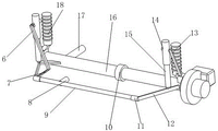
Fig. 1 is a schematic perspective view of the present invention.
Fig. 2 is a schematic perspective view of the lateral stabilizing mechanism of the present invention.
Detailed Description
The following provides a preferred embodiment of the present invention with reference to the accompanying drawings to explain the technical solutions of the present invention in detail.
As shown in fig. 1 to 2, the utility model discloses a brake disc 1, directive wheel fixed disk 2, braking pincers 3, transverse stabilizing mechanism 4, directive wheel fixed disk 5, the one end of brake disc 1 links to each other with transverse stabilizing mechanism 4, and the one end of directive wheel fixed disk 2 links to each other with brake disc 1, and braking pincers 3 are located brake disc 1, and transverse stabilizing mechanism 4 is located between brake disc 1 and the directive wheel fixed disk 5, wherein: the transverse stabilizing mechanism 4 comprises an upper swing arm 6, a swing arm connecting rod 7, a guide rod system 8, a transverse connecting rod 9, a universal joint 10, a fixing plate 11, a transverse thrust rod 12, a steering knuckle 13, a nylon sleeve 14, a shock absorber 15, a torsion beam 16, a lower swing arm 17 and a shock absorbing spring 18, wherein one end of the upper swing arm 6 is connected with the nylon sleeve 14, the other end of the upper swing arm 6 is connected with the swing arm connecting rod 7, one end of the swing arm connecting rod 7 is connected with the transverse connecting rod 9, the guide rod system 8 is positioned on the transverse connecting rod 9, the transverse connecting rod 9 is connected with the transverse thrust rod 12 through the fixing plate 11, the universal joint 10 is positioned on the torsion beam 16, one end of the steering knuckle 13 is connected with the nylon sleeve 14, the other end of the steering knuckle 13 is connected with the brake disc 1, one end of the nylon sleeve 14 is connected with the shock absorber 15, one end of the shock absorber 15 is positioned, one end of the damper spring 18 is connected to the torsion beam 16.
The lower swing arm 17 is provided with a lower swing arm connecting rod which is connected with each other, so that the stability can be improved.
The steering wheel fixing disc 2 is provided with a screw hole, so that the steering wheel fixing disc can be conveniently fixed.
The tail part of the damping spring 18 is provided with a spring connecting piece, so that the vibration of the wheel can be reduced.
The brake caliper 3 is provided with a brake pad, which can perform a braking function.
The working principle of the utility model is as follows: the utility model has the advantages of simple structure and reasonable design, be equipped with transverse stabilizing mechanism on it, can be when the car is crossing the bend, can cause heeling of automobile body because of the effect of centrifugal force, lead to the interior wheel of bending to hang tensile, the outer wheel of bending hangs the compression, cause the pole body of preventing the tilting rod to twist reverse, produce very big torsion, reverse action hangs, prevent that the automobile body from taking place too big transverse heeling and improving the ride comfort when turning, it includes the brake disc, the directive wheel fixed disk, braking pincers, transverse stabilizing mechanism, the directive wheel fixed disk, the brake disc is used for producing the part that blocks vehicle motion or motion trend brake force in braking system, the directive wheel fixed disk is used for installing the steering drive wheel, braking pincers are one kind of disc brake and are used for producing braking moment, the part that is used for blockking vehicle motion or motion trend turns to the drive wheel because the driving system all is located, the drive shaft and the rear differential to the rear wheel are omitted, the space is not occupied, the volume inside the vehicle body is increased, and the vehicle can be rotated and driven to advance. The transverse stabilizing mechanism is used for improving the running smoothness of an automobile, improving the lateral inclination rigidity of a suspension, reducing the inclination angle of an automobile body and improving the performance of a safe automobile, and comprises an upper swing arm, a swing arm connecting rod, a guide rod system, a transverse connecting rod, a universal joint, a fixing plate, a transverse thrust rod, a steering knuckle, a nylon sleeve, a shock absorber, a torsion beam, a lower swing arm and a shock absorbing spring, wherein the upper swing arm is a bridge of a wheel connecting chassis and can stabilize a device and improve the shock absorbing capacity of the wheel, the swing arm connecting rod is used for connecting the swing arm to the transverse stabilizing rod, the guide rod system is used for guiding the wheel and the transverse rod when the automobile runs, the transverse connecting rod is also called an anti-tilt rod and a balance rod and is an auxiliary elastic element in the automobile suspension, the universal joint is a part for realizing variable-angle power transmission and is used for changing the position of the direction of a transmission axis and is a joint part, the fixed plate is used for fixing the transverse stabilizer bar, the transverse thrust bar is used for generating transverse thrust, the steering knuckle transmits and bears the front load of the automobile, the front wheel is supported and driven to rotate around the main pin so as to steer the automobile, the nylon sleeve is used for attenuating the vibration of the elastic element and absorbing and radiating the vibration energy, the vibration absorber is an appliance for accelerating the attenuation of the vibration of the frame and the automobile body so as to improve the driving smoothness of the automobile, the torsion beam is one of automobile suspension type and balances the vertical jumping of the left wheel and the right wheel through a torsion beam so as to reduce the shaking of the automobile and keep the stability of the automobile, the lower swing arm is used for connecting the middle beam of the automobile body, the steering and vibration attenuation performances of the wheels can be enhanced, and the vibration attenuation spring is a common elastic element and has the advantages of good stability, low noise, good.
To sum up, the utility model discloses can utilize transverse stabilization mechanism, can be when the car is crossing curved, because the effect of centrifugal force can cause heeling of automobile body, it is tensile to lead to the interior wheel of turning to hang, and the wheel of turning hangs the compression, and the pole body that causes the anti-roll pole twists reverse, produces very big torsion, and reverse action hangs, prevents that the automobile body from taking place too big horizontal heeling and improving the ride comfort when turning.
The above-mentioned embodiments further explain the technical problems, technical solutions and advantages of the present invention in detail, it should be understood that the above-mentioned embodiments are only examples of the present invention, and are not intended to limit the present invention, and any modifications, equivalent substitutions, improvements, etc. made within the spirit and principle of the present invention should be included in the scope of the present invention.
Claims (5)
1. The utility model provides a novel big torsion car lateral stabilization device, its characterized in that, it includes brake disc, directive wheel fixed disk, braking pincers, lateral stabilization mechanism, directive wheel fixed disk, and the one end and the lateral stabilization mechanism of brake disc link to each other, and the one end and the brake disc of directive wheel fixed disk link to each other, and braking pincers are located the brake disc, and lateral stabilization mechanism is located between brake disc and the directive wheel fixed disk, wherein: the transverse stabilizing mechanism comprises an upper swing arm, a swing arm connecting rod, a guide rod system, a transverse connecting rod, a universal joint, a fixing plate, a transverse thrust rod, a steering knuckle, a nylon sleeve, a vibration absorber, a torsion beam, a lower swing arm, a vibration-absorbing spring, one end of the upper swing arm is connected with the nylon sleeve, the other end of the upper swing arm is connected with the swing arm connecting rod, one end of the swing arm connecting rod is connected with the transverse connecting rod, the guide rod system is located on the transverse connecting rod, the transverse connecting rod is connected with the transverse thrust rod through the fixing plate, the universal joint is located on the torsion beam, one end of the steering knuckle is connected with the nylon sleeve, the other end of the steering knuckle is connected with a brake disc, one end of the nylon sleeve is connected with the vibration absorber, one end of the vibration absorber is located on the.
2. The novel large-torque automobile transverse stabilizing device as claimed in claim 1, wherein the lower swing arm is provided with a lower swing arm connecting rod connected with the lower swing arm.
3. The novel high-torque automobile transverse stabilizing device as claimed in claim 1, wherein the steering wheel fixing disc is provided with a screw hole.
4. The novel large-torque automobile transverse stabilizing device is characterized in that a spring connecting piece is arranged at the tail part of the damping spring.
5. The novel high torque vehicle lateral stabilizer device as claimed in claim 1, wherein the brake caliper is provided with a brake pad.
Priority Applications (1)
| Application Number | Priority Date | Filing Date | Title |
|---|---|---|---|
| CN201821993493.3U CN209938247U (en) | 2018-11-30 | 2018-11-30 | Novel large-torque automobile transverse stabilizing device |
Applications Claiming Priority (1)
| Application Number | Priority Date | Filing Date | Title |
|---|---|---|---|
| CN201821993493.3U CN209938247U (en) | 2018-11-30 | 2018-11-30 | Novel large-torque automobile transverse stabilizing device |
Publications (1)
| Publication Number | Publication Date |
|---|---|
| CN209938247U true CN209938247U (en) | 2020-01-14 |
Family
ID=69118484
Family Applications (1)
| Application Number | Title | Priority Date | Filing Date |
|---|---|---|---|
| CN201821993493.3U Active CN209938247U (en) | 2018-11-30 | 2018-11-30 | Novel large-torque automobile transverse stabilizing device |
Country Status (1)
| Country | Link |
|---|---|
| CN (1) | CN209938247U (en) |
Cited By (1)
| Publication number | Priority date | Publication date | Assignee | Title |
|---|---|---|---|---|
| CN112690154A (en) * | 2021-01-18 | 2021-04-23 | 华南农业大学 | Greenhouse spraying system |
-
2018
- 2018-11-30 CN CN201821993493.3U patent/CN209938247U/en active Active
Cited By (1)
| Publication number | Priority date | Publication date | Assignee | Title |
|---|---|---|---|---|
| CN112690154A (en) * | 2021-01-18 | 2021-04-23 | 华南农业大学 | Greenhouse spraying system |
Similar Documents
| Publication | Publication Date | Title |
|---|---|---|
| CN209938247U (en) | Novel large-torque automobile transverse stabilizing device | |
| JPS63240408A (en) | Suspension device for automobile | |
| CN211308172U (en) | Automobile shock absorption chassis suspension device | |
| CN106347060A (en) | Balanced suspension and automobile | |
| CN210760117U (en) | Five-link rear suspension and vehicle structure with same | |
| CN209938246U (en) | High-strength anti-roll automobile transverse stabilizing system | |
| CN211969149U (en) | Vehicle and driving mechanism thereof | |
| CN209700324U (en) | A kind of four-wheel electric motor car independent suspension | |
| JP3701958B2 (en) | Subframe mounting bush | |
| KR20100058967A (en) | Suspension system for vehicle | |
| CN219927402U (en) | Rear axle assembly and all-terrain vehicle | |
| JP2006192932A (en) | Rear suspension device of automobile | |
| CN208558931U (en) | A kind of wheel independent suspension shockproof mechanism | |
| CN217753396U (en) | Automobile suspension | |
| CN220720763U (en) | Double-cross arm suspension system | |
| CN217260289U (en) | Rear suspension structure of unmanned drive-by-wire chassis | |
| JP3069022B2 (en) | Vehicle rear wheel suspension | |
| KR102638576B1 (en) | A variable suspension for mobility using twisted strings | |
| CN212098317U (en) | Reliable suspension system of semitrailer | |
| CN212099059U (en) | Safe and reliable semi-trailer frame system | |
| CN207984484U (en) | A kind of independent suspension | |
| CN108327474A (en) | A kind of wheel independent suspension shockproof mechanism | |
| KR100313789B1 (en) | Rear wheel suspension system of vehicle | |
| CN104589942A (en) | Torsion beam semi-independent suspension structure | |
| KR100530032B1 (en) | dual strut type suspension |
Legal Events
| Date | Code | Title | Description |
|---|---|---|---|
| GR01 | Patent grant | ||
| GR01 | Patent grant |