CN203664537U - Automatic feed and discharge device of hydraulic machine of automobile carling - Google Patents
Automatic feed and discharge device of hydraulic machine of automobile carling Download PDFInfo
- Publication number
- CN203664537U CN203664537U CN201320752456.4U CN201320752456U CN203664537U CN 203664537 U CN203664537 U CN 203664537U CN 201320752456 U CN201320752456 U CN 201320752456U CN 203664537 U CN203664537 U CN 203664537U
- Authority
- CN
- China
- Prior art keywords
- conveying mechanism
- lifting loads
- rack
- hydraulic press
- cylinder
- Prior art date
- Legal status (The legal status is an assumption and is not a legal conclusion. Google has not performed a legal analysis and makes no representation as to the accuracy of the status listed.)
- Expired - Lifetime
Links
- 230000007246 mechanism Effects 0.000 claims abstract description 38
- 239000000463 material Substances 0.000 claims description 29
- 230000008878 coupling Effects 0.000 claims description 13
- 238000010168 coupling process Methods 0.000 claims description 13
- 238000005859 coupling reaction Methods 0.000 claims description 13
- 230000009467 reduction Effects 0.000 claims description 13
- XEEYBQQBJWHFJM-UHFFFAOYSA-N Iron Chemical compound [Fe] XEEYBQQBJWHFJM-UHFFFAOYSA-N 0.000 claims description 6
- 238000001514 detection method Methods 0.000 claims description 6
- 230000005021 gait Effects 0.000 claims description 4
- 238000009434 installation Methods 0.000 claims description 4
- 230000001105 regulatory effect Effects 0.000 claims description 4
- 238000005452 bending Methods 0.000 claims description 3
- 229910052742 iron Inorganic materials 0.000 claims description 3
- 238000004519 manufacturing process Methods 0.000 abstract description 8
- 238000000034 method Methods 0.000 abstract description 4
- 230000008569 process Effects 0.000 abstract description 4
- 230000005540 biological transmission Effects 0.000 abstract 2
- 239000003638 chemical reducing agent Substances 0.000 abstract 1
- 238000007599 discharging Methods 0.000 abstract 1
- 238000004080 punching Methods 0.000 abstract 1
- 238000007493 shaping process Methods 0.000 description 4
- 239000002184 metal Substances 0.000 description 2
- 229910052751 metal Inorganic materials 0.000 description 2
- 230000007812 deficiency Effects 0.000 description 1
- 230000000694 effects Effects 0.000 description 1
- 238000005516 engineering process Methods 0.000 description 1
- 230000005284 excitation Effects 0.000 description 1
- 239000000203 mixture Substances 0.000 description 1
- 230000001737 promoting effect Effects 0.000 description 1
- 230000008439 repair process Effects 0.000 description 1
- 230000003252 repetitive effect Effects 0.000 description 1
- 238000003466 welding Methods 0.000 description 1
Images

Abstract
The utility model discloses an automatic feed and discharge device of a hydraulic machine of an automobile carling. The automatic feed and discharge device comprises a feed conveying mechanism, a discharge conveying mechanism, a lateral pushing device, an electronic control system and the like. According to the feed process, two motors are adopted to control an electromagnetic lifter to move front and back and to move vertically respectively, the advancing speed of the electromagnetic lifter is controlled through a worm gear reducer and a gear rack transmission mechanism assembly, the gear rack transmission mechanism assembly controls the advancing accuracy of the electromagnetic lifter, a roller type conveyor is utilized for feeding, a plate type conveying mechanism is adopted at the discharge side for discharging, the feed conveying mechanism and the lateral pushing device are located on the front side of the hydraulic machine, and the discharge conveying mechanism is located on the rear side of the hydraulic machine. The automatic feed and discharge device is suitable for large-size punching machines and equipment not convenient in feed and discharge and can achieve automation and continuation of programs, manpower is not required, working efficiency is largely improved, the labor intensity of workers is relieved, fewer people are needed, labor cost is lowered, the degree of automation of a production line is increased, and the potential safety hazard caused by manual operation is avoided.
Description
Technical field:
The utility model relates to machinery and electric equipment technical field of automation, is a kind of automobile longitudinal girder hydraulic press automatic loading and unloading device specifically.
Background technology:
At present in Sheet Metal Processing feeding process, due to the inconvenience of artificial workpiece loading and unloading, can not realize automation, the serialization of program, inefficiency, labor strength is large, and very easily there is potential safety hazard in manual operation, bring larger investment to production process, cause that production efficiency is low, production and administration high in cost of production problem.
Utility model content:
The purpose of this utility model is the deficiency that overcomes above-mentioned prior art, and a kind of automobile longitudinal girder hydraulic press automatic loading and unloading device is provided, mainly solve in existing Sheet Metal Processing feeding process that manual operation efficiency is low, intensity large, poor stability and high in cost of production problem.
The technical solution of the utility model is: a kind of automobile longitudinal girder hydraulic press automatic loading and unloading device, and its special character is, comprises material loading conveying mechanism, blanking conveying mechanism, side direction material-pulling device and electric-control system;
Described material loading conveying mechanism is made up of the first shaft coupling, worm type of reduction gearing, rack and pinion drive mechanism assembly, the second shaft coupling, automatic material-absorbing device, Electromagnetic slings for lifting loads and roll-type transporting device, described Electromagnetic slings for lifting loads is divided into automatic material-absorbing device, Electromagnetic slings for lifting loads provides power by middle motor, control before and after Electromagnetic slings for lifting loads and move up and down, Electromagnetic slings for lifting loads top connects the rack-track of rack and pinion drive mechanism assembly, middle motor below connects the power shaft of worm type of reduction gearing by the first shaft coupling, utilize the second shaft coupling that the gear input shaft in rack and pinion drive mechanism assembly is connected with the output shaft in worm type of reduction gearing, pass through worm type of reduction gearing, rack and pinion drive mechanism assembly control Electromagnetic slings for lifting loads gait of march, the precision that rack and pinion drive mechanism assembly control Electromagnetic slings for lifting loads is advanced, described roll-type transporting device is arranged on Electromagnetic slings for lifting loads below, and extend to hydraulic press inside, adopt four roller paths, every conveyer is made up of housing, conveying roller, bearing, sprocket wheel, chain, drive motors, bearing and sprocket wheel are installed in outside, a guard shield of outside installation, drive motors is arranged on bottom, the end of described material loading conveying mechanism establish detect sheet material be transported to position material loading approach switch,
Described blanking conveying mechanism adopts two platen type conveyers, every conveyer is made up of housing, chain, bracket, drive motors, housing is welded by iron plate bending, the large roller chain of inner employing, on each chain sheet with bent plate, bracket is fixed on bent plate, and drive motors is arranged on bottom; There is 1 detection finished product to be transported to the approach switch of position at the end of whole piece material loading pipeline;
Described side direction material-pulling device is made up of three cover cylinders, and every cover cylinder comprises a material loading cylinder and a blanking cylinder, and two cylinders are arranged on fixed support; The front end of each cylinder is installed movable pawling, and air volume regulating valve and sense switch are installed on each cylinder;
Described electric-control system is made up of electric cabinet, low voltage component, button; Electric cabinet is located at separately the outside of hydraulic press, and switch, button, contactor, relay, PLC, the various manipulations of magnetic valve, control, display element are inside housed.
Further, described fixed support is fixed on the column of hydraulic press.
Compared with the prior art a kind of automobile longitudinal girder hydraulic press automatic loading and unloading device described in the utility model has following good effect, can realize automatic charging, feeding and blanking, production efficiency is high, reduces labour intensity, safe, convenient management reduces production costs simultaneously.
Accompanying drawing explanation:
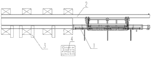
Fig. 1 the utility model structural representation.
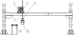
The structural representation of Fig. 2 material loading conveying mechanism of the present utility model;
Fig. 3 is the side view of Fig. 2.
The specific embodiment:
Below in conjunction with drawings and the specific embodiments, the utility model is described in further details; Illustrated embodiment is only for explaining the utility model, not for limiting scope of the present utility model.
Embodiment 1, referring to Fig. 1,2,3, take 6300 tons of automobile longitudinal girder hydraulic press automatic loading and unloading devices as example;
First be processed into Electromagnetic slings for lifting loads 15, Electromagnetic slings for lifting loads 15 provides power by middle motor 18, control the front and back of Electromagnetic slings for lifting loads 15 and move up and down, above Electromagnetic slings for lifting loads 15, connect the rack-track in rack and pinion drive mechanism assembly 13, middle motor 18 belows connect the power shaft of worm type of reduction gearing 12 by the first shaft coupling 11, utilize the second shaft coupling 17 that the gear input shaft in rack and pinion drive mechanism assembly 13 is connected with the output shaft in worm type of reduction gearing 12, by worm type of reduction gearing 12, rack and pinion drive mechanism assembly 13 is controlled Electromagnetic slings for lifting loads 15 gait of march, rack and pinion drive mechanism assembly 13 is controlled the precision that Electromagnetic slings for lifting loads 15 is advanced, 15 times automatic material-absorbing device 14 is installed at Electromagnetic slings for lifting loads, roll-type transporting device 16 is installed below automatic material-absorbing device 14, and extend to hydraulic press inside, adopt four roller paths, every conveyer is made up of housing, conveying roller, bearing, sprocket wheel, chain, drive motors, bearing and sprocket wheel are installed in outside, a guard shield of outside installation, drive motors is arranged on bottom, above-mentioned the first shaft coupling 11, worm type of reduction gearing 12, rack and pinion drive mechanism assembly 13, the second shaft coupling 17, automatic material-absorbing device 14, Electromagnetic slings for lifting loads 15 and roll-type transporting device 16 form material loading conveying mechanism 1, whether the end installation and measuring sheet material at material loading conveying mechanism 1 is carried the material loading approach switch putting in place, carry and put in place for detection of sheet material,
Adopt two platen type conveyers to form blanking conveyor mechanism 2, every conveyer is made up of housing, chain, bracket, drive motors, housing adopts 4mm iron plate bending welding, the inner large roller carrier chain that adopts pitch 50.8, on each chain sheet, with bent plate, bracket is screwed on bent plate, be easy to remove and repair, drive motors is arranged on bottom, does not take the space on top, and the product after convenient shaping is hung oneself away from conveyer; In addition, also have 1 detection finished product to be transported to the approach switch of position at the end of whole piece material loading pipeline, whether carry and put in place for detection of finished product;
Adopt three cover cylinder compositions to form side direction material-pulling device 3, every cover cylinder comprises a material loading cylinder and a blanking cylinder, and cylinder is arranged on fixed support; Fixed support is fixed on the column of hydraulic press; The front end of each cylinder is installed movable pawling, be used for promoting sheet material or finished product, air volume regulating valve and sense switch are installed on each cylinder, air volume regulating valve is for both stretching speeds of adjusting cylinders of size of adjustable pressure, whether sense switch stretches out and puts in place or shrink and put in place for detection of cylinder, is convenient to carry out the work of a whole set of hydraulic press according to the signal detecting;
Form and form electric-control system 4 by electric cabinet, low voltage component, button; Electric cabinet is arranged separately in the outside of hydraulic press, and switch, button, contactor, relay, PLC, the various manipulations of magnetic valve, control, display element are inside housed, and facilitates staff to operate;
Form a kind of automobile longitudinal girder hydraulic press automatic loading and unloading device of the present utility model by above-mentioned material loading conveying mechanism 1, blanking conveyor mechanism 2, side direction material-pulling device 3 and electric-control system 4.
A kind of automobile longitudinal girder hydraulic press automatic loading and unloading device described in the utility model, material loading side adopts electromagnetic lifter and roller path feeding, and blanking side adopts apron conveyor blanking.Automatic loading/unloading process: first, utilize two motors control respectively the front and back of Electromagnetic slings for lifting loads and move up and down when material loading, by shaft coupling and worm type of reduction gearing control gait of march, the precision of utilizing the control of rack-and-pinion track to advance; Automatic material-absorbing device is by excitation, and the secondary lifting of degaussing suction gripper, once advances and retreat and move, and the longeron of primary importance on bin is winched on rollgang, and then repetitive operation, winches to the lining beam of the second place on bin on the longeron of roller-way, realizes location automatically; Material loading side roller path is transported to plate in hydraulic press, and apart from 5970mm position, hydraulic press center line left side, feeder stops feeding; The material loading cylinder of side direction material-pulling device by plate by being pushed on roller-way on shaping dies, hydraulic press starts compacting (now feeding device material loading simultaneously), after shaping completes, hydraulic press is by workpiece jack-up, the blanking cylinder of side direction material-pulling device is pushed into the product after being shaped on blanking leaf chain, and apron conveyor is delivered to workpiece outside hydraulic press, therewith when side direction material-pulling device pusher, opposite side is pushed into next piece plate on shaping dies to material-pulling device, completes an operation cycle.
Claims (2)
1. an automobile longitudinal girder hydraulic press automatic loading and unloading device, is characterized in that, comprises material loading conveying mechanism (1), blanking conveying mechanism (2), side direction material-pulling device (3) and electric-control system (4);
Described material loading conveying mechanism (1) is made up of the first shaft coupling (11), worm type of reduction gearing (12), rack and pinion drive mechanism assembly (13), the second shaft coupling (17), automatic material-absorbing device (14), Electromagnetic slings for lifting loads (15) and roll-type transporting device (16), described Electromagnetic slings for lifting loads (15) is divided into automatic material-absorbing device (14), Electromagnetic slings for lifting loads (15) provides power by middle motor (18), control before and after Electromagnetic slings for lifting loads (15) and move up and down, Electromagnetic slings for lifting loads (15) top connects the rack-track of rack and pinion drive mechanism assembly (13), middle motor (18) below connects the power shaft of worm type of reduction gearing (12) by the first shaft coupling (11), utilize the second shaft coupling (17) that the gear input shaft in rack and pinion drive mechanism assembly (13) is connected with the output shaft in worm type of reduction gearing (12), by worm type of reduction gearing (12), rack and pinion drive mechanism assembly (13) is controlled Electromagnetic slings for lifting loads (15) gait of march, rack and pinion drive mechanism assembly (13) is controlled the precision that Electromagnetic slings for lifting loads (15) is advanced, described roll-type transporting device (16) is arranged on Electromagnetic slings for lifting loads (15) below, and extend to hydraulic press inside, adopt four roller paths, every conveyer is made up of housing, conveying roller, bearing, sprocket wheel, chain, drive motors, bearing and sprocket wheel are installed in outside, a guard shield of outside installation, drive motors is arranged on bottom, the end of described material loading conveying mechanism (1) establish detect sheet material be transported to position material loading approach switch,
Described blanking conveying mechanism (2) adopts two platen type conveyers, every conveyer is made up of housing, chain, bracket, drive motors, housing is welded by iron plate bending, the large roller chain of inner employing, on each chain sheet with bent plate, bracket is fixed on bent plate, and drive motors is arranged on bottom; There is 1 detection finished product to be transported to the approach switch of position at the end of whole piece material loading pipeline;
Described side direction material-pulling device (3) is made up of three cover cylinders, and every cover cylinder comprises a material loading cylinder and a blanking cylinder, and cylinder is arranged on fixed support; The front end of each cylinder is installed movable pawling, and air volume regulating valve and sense switch are installed on each cylinder;
Described electric-control system (4) is made up of electric cabinet, low voltage component, button; Electric cabinet is located at separately the outside of hydraulic press, and switch, button, contactor, relay, PLC, the various manipulations of magnetic valve, control, display element are inside housed.
2. a kind of automobile longitudinal girder hydraulic press automatic loading and unloading device according to claim 1, is characterized in that, described fixed support is fixed on the column of hydraulic press.
Priority Applications (1)
| Application Number | Priority Date | Filing Date | Title |
|---|---|---|---|
| CN201320752456.4U CN203664537U (en) | 2013-11-26 | 2013-11-26 | Automatic feed and discharge device of hydraulic machine of automobile carling |
Applications Claiming Priority (1)
| Application Number | Priority Date | Filing Date | Title |
|---|---|---|---|
| CN201320752456.4U CN203664537U (en) | 2013-11-26 | 2013-11-26 | Automatic feed and discharge device of hydraulic machine of automobile carling |
Publications (1)
| Publication Number | Publication Date |
|---|---|
| CN203664537U true CN203664537U (en) | 2014-06-25 |
Family
ID=50960870
Family Applications (1)
| Application Number | Title | Priority Date | Filing Date |
|---|---|---|---|
| CN201320752456.4U Expired - Lifetime CN203664537U (en) | 2013-11-26 | 2013-11-26 | Automatic feed and discharge device of hydraulic machine of automobile carling |
Country Status (1)
| Country | Link |
|---|---|
| CN (1) | CN203664537U (en) |
Cited By (4)
| Publication number | Priority date | Publication date | Assignee | Title |
|---|---|---|---|---|
| CN103639315A (en) * | 2013-11-26 | 2014-03-19 | 山东蓬翔汽车有限公司 | Automatic feeding and discharging device of automotive longitudinal beam hydraulic press |
| CN104440429A (en) * | 2014-11-03 | 2015-03-25 | 宁波市镇海元益机电制造有限公司 | Automatic feeding and discharging device control system for plugging and grinding operation and control method |
| CN108465744A (en) * | 2018-03-09 | 2018-08-31 | 安徽江淮汽车集团股份有限公司 | A kind of transport system of uncoiling blanking mold |
| CN109940402A (en) * | 2019-04-28 | 2019-06-28 | 重庆中和智能装备有限公司 | A kind of shear for steel grating structure, steel grating production bus and steel grating automatic production method |
-
2013
- 2013-11-26 CN CN201320752456.4U patent/CN203664537U/en not_active Expired - Lifetime
Cited By (5)
| Publication number | Priority date | Publication date | Assignee | Title |
|---|---|---|---|---|
| CN103639315A (en) * | 2013-11-26 | 2014-03-19 | 山东蓬翔汽车有限公司 | Automatic feeding and discharging device of automotive longitudinal beam hydraulic press |
| CN104440429A (en) * | 2014-11-03 | 2015-03-25 | 宁波市镇海元益机电制造有限公司 | Automatic feeding and discharging device control system for plugging and grinding operation and control method |
| CN108465744A (en) * | 2018-03-09 | 2018-08-31 | 安徽江淮汽车集团股份有限公司 | A kind of transport system of uncoiling blanking mold |
| CN109940402A (en) * | 2019-04-28 | 2019-06-28 | 重庆中和智能装备有限公司 | A kind of shear for steel grating structure, steel grating production bus and steel grating automatic production method |
| CN109940402B (en) * | 2019-04-28 | 2023-10-20 | 太仓金硕智控设备有限公司 | Steel grating shearing mechanism, steel grating production bus and steel grating automatic production method |
Similar Documents
| Publication | Publication Date | Title |
|---|---|---|
| CN101745908B (en) | Mechanical arm and metal plate stamping device using same | |
| CN203664537U (en) | Automatic feed and discharge device of hydraulic machine of automobile carling | |
| CN204430786U (en) | Full-automatic photovoltaic frame production line | |
| CN203817219U (en) | Feeding device for round pipe punch | |
| CN203806529U (en) | Conveying device of fully-automatic multi-station three-dimensional pipe punching equipment | |
| CN103639252A (en) | Flexible full-automatic plate rolling production line | |
| CN104925497B (en) | A kind of C-type steel induction system clamping-type upending device | |
| CN203581793U (en) | Grain and oil material conveying mechanism | |
| CN104909148A (en) | C-shaped steel overlapping and buckling conveying system | |
| CN202200583U (en) | Automatic conveying device for material loading and material unloading of punching equipment | |
| CN105598313B (en) | A kind of full-automatic shear feeder | |
| CN204727211U (en) | A kind of C-type steel delivery system upset blanking device | |
| CN205085605U (en) | Automatic change worm axle roll extrusion equipment | |
| CN102700990B (en) | Fully automatic material cutting machine | |
| CN205732651U (en) | Bin double automatic charging machine | |
| CN203592029U (en) | Flexible fully automatic coiled plate production line | |
| CN203281757U (en) | Automobile press line waste collection system | |
| CN207205264U (en) | A kind of Intelligent mobile feed device | |
| CN201201241Y (en) | Manipulator and metal plate stamping processing equipment using the same | |
| CN103639315A (en) | Automatic feeding and discharging device of automotive longitudinal beam hydraulic press | |
| CN207861245U (en) | It is a kind of to come in and go out automatically curing chamber and the device of cooling chamber for compound material volume | |
| CN205341713U (en) | Full -automatic board feeder of cutting | |
| CN206456965U (en) | A kind of O-shaped tipper | |
| CN204361547U (en) | A kind of Offline transfer machine of armoured draw-out type AC closed switch apparatus | |
| CN104441048A (en) | Composite material plane forming machine |
Legal Events
| Date | Code | Title | Description |
|---|---|---|---|
| C14 | Grant of patent or utility model | ||
| GR01 | Patent grant | ||
| CX01 | Expiry of patent term |
Granted publication date: 20140625 |
|
| CX01 | Expiry of patent term |