CN203565582U - Three-shaft full-automatic rolling machine - Google Patents
Three-shaft full-automatic rolling machine Download PDFInfo
- Publication number
- CN203565582U CN203565582U CN201320619928.9U CN201320619928U CN203565582U CN 203565582 U CN203565582 U CN 203565582U CN 201320619928 U CN201320619928 U CN 201320619928U CN 203565582 U CN203565582 U CN 203565582U
- Authority
- CN
- China
- Prior art keywords
- plate
- cylinder
- full
- blowing
- action roller
- Prior art date
- Legal status (The legal status is an assumption and is not a legal conclusion. Google has not performed a legal analysis and makes no representation as to the accuracy of the status listed.)
- Withdrawn - After Issue
Links
Images


Landscapes
- Bending Of Plates, Rods, And Pipes (AREA)
Abstract
The utility model discloses a three-shaft full-automatic rolling machine. The three-shaft full-automatic rolling machine comprises a machine body, a machine head, a power driving system and a control system. A feeding mechanism and a discharging mechanism are located at the positions of a feeding port and a discharging port of the machine head, the machine head comprises a material conveying mechanism and a rolling and forming mechanism, a guide plate is arranged at the connecting position of the material conveying mechanism and the rolling and forming mechanism, the material conveying mechanism comprises a material sucking cylinder vertically arranged on the machine frame and a material sucking device, wherein the material sucking cylinder is used for driving the material sucking device to vertically move, and a material pushing cylinder driving the material sucking device to horizontally move is arranged at the front portion of the material sucking device. The three-shaft full-automatic rolling machine has the advantages of being simple in structure, convenient to maintain and wide in application range. In addition, parts are convenient to replace, full-automatic mechanical rolling is achieved, production efficiency is greatly improved, production cost is reduced, and the requirement for manufacturing workpieces of different diameters can be met.
Description
Technical field
The utility model relates to furling plate round machine, especially relates to the full-automatic furling plate round machine of a kind of three axle.
Background technology
The structure of conventional roll circular knitting machine is more complicated, and energy consumption is high, adjusts inconvenience, and the scope of application is limited, is difficult to meet the making of the large small workpiece of various different-diameters, and dismounting is also extremely inconvenient in the maintenance process in later stage.
Summary of the invention
It is a kind of simple in structure, easy to maintenance that the utility model object is to provide, and can meet the full-automatic furling plate round machine of three axles that different-diameter workpiece is made.
For achieving the above object, the utility model can be taked following technical proposals:
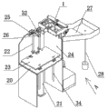
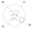
The full-automatic furling plate round machine of three axle described in the utility model, comprise fuselage, head and and the power drive line control system of unifying, on described fuselage, be positioned at head charging aperture and discharging opening place is respectively arranged with discharge mechanism and discharging mechanism, described head comprises feed mechanism and the cylinder rolling forming mechanism being arranged in frame, joining place at described feed mechanism and cylinder rolling forming mechanism is provided with guide plate, described feed mechanism comprises by its device for suction material moving up and down of suction air cylinder driven being vertically set in frame, in described device for suction material front portion, be provided with the pusher cylinder that drives its horizontal movement, described cylinder rolling forming mechanism comprises and is arranged on fixed roll axle and the action roller shaft that is driven its rotation in frame by synchronizing wheel, in described frame, be parallel to action roller shaft direction and be provided with bolster, on described bolster, turning set is equipped with the mould being used in conjunction with action roller shaft, described mould comprises by the bolt plate after the moulding header board that is integrated and moulding that is spirally connected, on described moulding header board, with respect to action roller shaft one side, offer the arc groove face that is mated use, on described moulding header board top, be fixedly installed pressing plate, at the two ends of described action roller shaft, be provided with the locating piece being used in conjunction with described pressing plate, above described pressing plate, be provided with mold adjustment device, described mold adjustment device comprise be arranged on the location-plate in frame and be movably arranged on location-plate and pressing plate between adjustment screw rod, the upper end of described adjustment screw rod is fixed on location-plate by adjusting nut, and its lower end is hinged with the U-shaped piece being fixed on pressing plate, between described location-plate and action roller shaft, by adjustment block, be provided with stage clip, described discharge mechanism comprises the blowing platform being horizontally set on fuselage and is arranged on blowing platform its blowing plate moving up and down along rod by Driven by Hydraulic Cylinder, in the place ahead of described blowing plate, be positioned at furling plate round machine structure lower vertical and be provided with forward cam, above described blowing plate, be provided with holding pad and pressure wheel, described discharging mechanism comprises charging tray and the charging tray support that is engaged on furling plate round machine structure discharging opening place.
On described fuselage, be provided with lower limit sense switch, upper limit sense switch, working position sense switch and the material of blowing plate without sense switch.
On described charging tray, be provided with the full sense switch of material.
Between described blowing platform and blowing plate, be vertically installed with guiding optical axis.
The cylinder barrel end of described suction cylinder is fixed on along on the slide plate of frame horizontal movement, and described slide plate is fixedly connected with the tailpiece of the piston rod of pusher cylinder; Described device for suction material comprises the linking arm that is arranged on suction cylinder piston boom end, in described linking arm bottom, slides and is provided with a plurality of slide blocks, in described slide block bottom, is provided with sucker.
Between described fixed roll axle and action roller wheel, by driving gear and the driven gear being separately positioned on it, be connected by meshing transmission.
The utility model advantage is simple in structure, and part exchanging is convenient, is convenient to safeguard, has realized full-automatic mechanical volume circle, has greatly improved production efficiency, has reduced production cost, and the scope of application is wide, can meet the making of different-diameter workpiece.
Accompanying drawing explanation
Fig. 1 is structural representation of the present utility model.
Fig. 2 is that the A of Fig. 1 is to structural representation.
Fig. 3 is the I portion enlarged drawing of Fig. 2.
Fig. 4 is the structural representation of head in Fig. 1.
Fig. 5 is the plan structure schematic diagram of Fig. 4.
Fig. 6 is the B-B cutaway view of Fig. 5.
Fig. 7 is the C-C cutaway view of Fig. 5.
The specific embodiment
As Fig. 1, 2, 3, 4, 5, 6, shown in 7, the full-automatic furling plate round machine of three axle described in the utility model, comprise fuselage, head 1 and and the power drive line control system of unifying, at described fuselage, be positioned at described head 1 charging aperture and discharging opening place is respectively arranged with discharge mechanism and discharging mechanism, described head 1 comprises feed mechanism and the cylinder rolling forming mechanism being arranged in frame 2, joining place at described feed mechanism and cylinder rolling forming mechanism is provided with guide plate 3, described feed mechanism comprises by suction cylinder 4 its device for suction materials that move up and down of driving that are vertically set in frame 2, in described device for suction material front portion, be provided with the pusher cylinder 5 that drives its horizontal movement, the cylinder barrel end of described suction cylinder 4 is fixed on along on the slide plate 35 of frame 2 horizontal movements, described slide plate 35 is fixedly connected with the tailpiece of the piston rod of pusher cylinder 5, described device for suction material comprises the linking arm 36 that is arranged on suction cylinder 4 piston rod ends, in described linking arm 36 bottoms, slides and is provided with a plurality of slide blocks 37, in described slide block 37 bottoms, is provided with sucker 38.As shown in Figure 6,7, described cylinder rolling forming mechanism comprises and is arranged in frame 2 fixed roll axle 7 and the action roller shaft 8 that is driven its rotations by synchronizing wheel 6, described fixed roll axle 7 and 8, action roller wheel are connected by meshing transmission by driving gear 39 and the driven gear 40 being separately positioned on it, described synchronizing wheel 6 is connected with the output wheel that is arranged on the motor 41 on fuselage by belt, in described frame 2, be parallel to action roller shaft 8 directions and be provided with bolster 9, on described bolster 9, turning set is equipped with the mould being used in conjunction with action roller shaft 8; Described mould comprises by the bolt plate 11 after the moulding header board 10 that is integrated and moulding that is spirally connected, on described moulding header board 10, with respect to action roller shaft 8 one sides, offer the arc groove face that is mated use, on described moulding header board 10 tops, be fixedly installed pressing plate 12, at the two ends of described action roller shaft 8, be provided with the locating piece 13 being used in conjunction with described pressing plate 12; Above described pressing plate 12, be provided with mold adjustment device, described mold adjustment device comprise the location-plate 14 being arranged in frame 2 and be movably arranged on location-plate 14 and pressing plate 12 between adjustment screw rod 15, the upper end of described adjustment screw rod 15 is fixed on location-plate 14 by adjusting nut 16, its lower end is hinged with the U-shaped piece 17 being fixed on pressing plate 12, by adjusting nut 16, be adjusted to the gap between mould and action roller shaft 8, thereby can roll out the different workpiece of diameter; Between described location-plate 14 and action roller shaft 8, by adjustment block 18, be provided with stage clip 19, action roller shaft 8 can be finely tuned along the vertical direction, the scope of adjusting is decided by the pressure of stage clip 19, thereby meet different-thickness material, from the gap between fixed roll axle 7 and action roller shaft 8, passes through; Described discharge mechanism comprises the blowing platform 20 being horizontally set on fuselage and is arranged on blowing platform 20 by hydraulic cylinder 21 its blowing plates 23 that move up and down along rod 22 of driving, between described blowing platform 20 and blowing plate 23, be vertically installed with guiding optical axis 34, utilize 34 pairs of blowing plate 23 lifting process of guiding optical axis to proceed to guide-localization, on described fuselage, be provided with lower limit sense switch 29, upper limit sense switch 30, working position sense switch 31 and the material of blowing plate 23 without sense switch 32; In the place ahead of described blowing plate 23, be positioned at furling plate round machine structure lower vertical and be provided with forward cam 24, above described blowing plate 23, be provided with holding pad 25 and pressure wheel 26; Described discharging mechanism comprises charging tray 27 and the charging tray support 28 that is engaged on furling plate round machine structure discharging opening place; on described charging tray 27, be provided with the full sense switch 33 of material; in order to guarantee safety; charging aperture position at head 1 is provided with double sheet detecting sensor; can hard stop when if device for suction material once picks up two materials, avoid the generation of contingency.
The utility model in use, first on blowing plate 23, pendulum is expected, after reaching a certain height, material expects automatically to brighten without sense switch 32, then by start button, utilize hydraulic cylinder 21 to make blowing plate 23 automatic-ascendings, after arriving certain altitude, working position sense switch 31 brightens, at this moment control system is sent a signal of telecommunication and is made suction cylinder 4 descending, after sucker 38 holds material, suction cylinder 4 resets, then control system is sent a signal of telecommunication and is made pusher cylinder 5 promote materials to move forward, then material enters cylinder rolling forming mechanism, under the roll-in of cylinder rolling forming mechanism, complete the volume circle action of workpiece, finally from discharging structure out, if the lamp went out for working position sense switch 31, blowing plate 23 under the promotion of hydraulic cylinder 21 by automatic-ascending, when bright the quitting work of working position sense switch 31 lamps, the continuity volume circle of the workpiece that circulated like this, represents that at this moment material is finished until material becomes to go out without sense switch 32 lamps, and then blowing plate 23 declines automatically, and placing materials carries out next operation cycle again.
Claims (6)
1. the full-automatic furling plate round machine of axle, comprise fuselage, head (1) and the power drive line control system of unifying, on described fuselage, be positioned at head (1) charging aperture and discharging opening place and be respectively arranged with discharge mechanism and discharging mechanism, it is characterized in that: described head (1) comprises feed mechanism and the cylinder rolling forming mechanism being arranged in frame (2), joining place at described feed mechanism and cylinder rolling forming mechanism is provided with guide plate (3), described feed mechanism comprises the device for suction material that drives it to move up and down by the suction cylinder (4) being vertically set in frame (2), in described device for suction material front portion, be provided with the pusher cylinder (5) that drives its horizontal movement, described cylinder rolling forming mechanism comprises that being arranged on frame (2) is above driven fixed roll axle (7) and the action roller shaft (8) of its rotation by synchronizing wheel (6), in described frame (2), be parallel to action roller shaft (8) direction and be provided with bolster (9), at the upper turning set of described bolster (9), the mould being used in conjunction with action roller shaft (8) is housed, described mould comprises by the bolt plate (11) after the moulding header board (10) that is integrated and moulding that is spirally connected, at described moulding header board (10), above with respect to action roller shaft (8) one sides, offer the arc groove face that is mated use, on described moulding header board (10) top, be fixedly installed pressing plate (12), at the two ends of described action roller shaft (8), be provided with the locating piece (13) being used in conjunction with described pressing plate (12), in described pressing plate (12) top, be provided with mold adjustment device, described mold adjustment device comprise the location-plate (14) being arranged in frame (2) and be movably arranged on location-plate (14) and pressing plate (12) between adjustment screw rod (15), it is upper that the upper end of described adjustment screw rod (15) is fixed on location-plate (14) by adjusting nut (16), and its lower end is hinged with the U-shaped piece (17) being fixed on pressing plate (12), between described location-plate (14) and action roller shaft (8), by adjustment block (18), be provided with stage clip (19), described discharge mechanism comprises the blowing platform (20) being horizontally set on fuselage and is arranged on the upper blowing plate (23) that drives it to move up and down along rod (22) by hydraulic cylinder (21) of blowing platform (20), in the place ahead of described blowing plate (23), be positioned at furling plate round machine structure lower vertical and be provided with forward cam (24), in described blowing plate (23) top, be provided with holding pad (25) and pressure wheel (26), described discharging mechanism comprises charging tray (27) and the charging tray support (28) that is engaged on furling plate round machine structure discharging opening place.
2. the full-automatic furling plate round machine of three axle according to claim 1, is characterized in that: on described fuselage, be provided with lower limit sense switch (29), upper limit sense switch (30), working position sense switch (31) and the material of blowing plate (23) without sense switch (32).
3. the full-automatic furling plate round machine of three axle according to claim 1, is characterized in that: on described charging tray (27), be provided with the full sense switch (33) of material.
4. the full-automatic furling plate round machine of three axle according to claim 1, is characterized in that: between described blowing platform (20) and blowing plate (23), be vertically installed with guiding optical axis (34).
5. the full-automatic furling plate round machine of three axle according to claim 1, it is characterized in that: the cylinder barrel end of described suction cylinder (4) is fixed on along the slide plate (35) of frame (2) horizontal movement upper, and described slide plate (35) is fixedly connected with the tailpiece of the piston rod of pusher cylinder (5); Described device for suction material comprises the linking arm (36) that is arranged on suction cylinder (4) piston rod end, in described linking arm (36) bottom, slides and is provided with a plurality of slide blocks (37), in described slide block (37) bottom, is provided with sucker (38).
6. the full-automatic furling plate round machine of three axle according to claim 1, is characterized in that: between described fixed roll axle (7) and action roller wheel (8), by driving gear (39) and the driven gear (40) being separately positioned on it, be connected by meshing transmission.
Priority Applications (1)
| Application Number | Priority Date | Filing Date | Title |
|---|---|---|---|
| CN201320619928.9U CN203565582U (en) | 2013-10-09 | 2013-10-09 | Three-shaft full-automatic rolling machine |
Applications Claiming Priority (1)
| Application Number | Priority Date | Filing Date | Title |
|---|---|---|---|
| CN201320619928.9U CN203565582U (en) | 2013-10-09 | 2013-10-09 | Three-shaft full-automatic rolling machine |
Publications (1)
| Publication Number | Publication Date |
|---|---|
| CN203565582U true CN203565582U (en) | 2014-04-30 |
Family
ID=50533341
Family Applications (1)
| Application Number | Title | Priority Date | Filing Date |
|---|---|---|---|
| CN201320619928.9U Withdrawn - After Issue CN203565582U (en) | 2013-10-09 | 2013-10-09 | Three-shaft full-automatic rolling machine |
Country Status (1)
| Country | Link |
|---|---|
| CN (1) | CN203565582U (en) |
Cited By (1)
| Publication number | Priority date | Publication date | Assignee | Title |
|---|---|---|---|---|
| CN103495628A (en) * | 2013-10-09 | 2014-01-08 | 郑州金泰制罐有限公司 | Three-shaft full-automatic edge rolling machine |
-
2013
- 2013-10-09 CN CN201320619928.9U patent/CN203565582U/en not_active Withdrawn - After Issue
Cited By (1)
| Publication number | Priority date | Publication date | Assignee | Title |
|---|---|---|---|---|
| CN103495628A (en) * | 2013-10-09 | 2014-01-08 | 郑州金泰制罐有限公司 | Three-shaft full-automatic edge rolling machine |
Similar Documents
| Publication | Publication Date | Title |
|---|---|---|
| CN205763192U (en) | A kind of sheet materials and parts automatic tamping equipment | |
| CN105058142A (en) | Plate type production line capable of automatically charging and discharging | |
| CN108405986A (en) | Aluminium bar high speed sawing Intelligent Machining assembly line | |
| CN203599375U (en) | Rapid forming stamping die | |
| CN204449078U (en) | A kind of material supporting rack and be provided with the bender of this material supporting rack | |
| CN203791529U (en) | Efficient automatic sides-seaming can-making machine | |
| CN105690661A (en) | Injection molded part full-automatic gate and shaping machine of injection molding machine | |
| CN105945111A (en) | Automatic profiling equipment for sheet parts | |
| CN206298081U (en) | A kind of automatic turning device of adjustable revolution center of gravity | |
| CN203565573U (en) | Full-automatic five-shaft edge rolling machine | |
| CN103495626B (en) | Upper-air-cylinder full-automatic edge rolling machine | |
| CN208696578U (en) | A kind of self-powered platform of laser cutting machine | |
| CN104128528A (en) | Automatic conveying mechanism for automobile press-fitting die | |
| CN204018587U (en) | The position limiting structure of discharge arm in numerical control sheet material bender | |
| CN103495625B (en) | Five-axis full-automatic rounding machine | |
| CN201357573Y (en) | Automatic rolling unloading mechanism of film blowing machine | |
| CN208561004U (en) | A kind of automatic lowering system and device | |
| CN203565582U (en) | Three-shaft full-automatic rolling machine | |
| CN103495628B (en) | Three-shaft full-automatic edge rolling machine | |
| CN204893264U (en) | A manipulator for directional sealing of tube | |
| CN104259263A (en) | Numerical control board bending machine | |
| CN200974289Y (en) | Plate feeding apparatus | |
| CN204052465U (en) | Horizontal sheet material apparatus for bending | |
| CN203565577U (en) | Upper-cylinder full-automatic edge rolling machine | |
| CN205110983U (en) | Fortune silk mechanism of spark -erosion wire cutting machine bed is exclusively used in |
Legal Events
| Date | Code | Title | Description |
|---|---|---|---|
| C14 | Grant of patent or utility model | ||
| GR01 | Patent grant | ||
| AV01 | Patent right actively abandoned |
Granted publication date: 20140430 Effective date of abandoning: 20150610 |
|
| RGAV | Abandon patent right to avoid regrant |