CN203530835U - Double-leg rigid-frame pier structure spanning existing building at small angle - Google Patents
Double-leg rigid-frame pier structure spanning existing building at small angle Download PDFInfo
- Publication number
- CN203530835U CN203530835U CN201320643968.7U CN201320643968U CN203530835U CN 203530835 U CN203530835 U CN 203530835U CN 201320643968 U CN201320643968 U CN 201320643968U CN 203530835 U CN203530835 U CN 203530835U
- Authority
- CN
- China
- Prior art keywords
- double
- rigid
- frame pier
- bridge
- existing building
- Prior art date
- Legal status (The legal status is an assumption and is not a legal conclusion. Google has not performed a legal analysis and makes no representation as to the accuracy of the status listed.)
- Expired - Lifetime
Links
- 238000007598 dipping method Methods 0.000 claims description 3
- 238000010276 construction Methods 0.000 abstract description 14
- 238000000034 method Methods 0.000 abstract description 2
- 238000012986 modification Methods 0.000 abstract 1
- 230000004048 modification Effects 0.000 abstract 1
- 239000011150 reinforced concrete Substances 0.000 abstract 1
- 238000005516 engineering process Methods 0.000 description 2
- 229910000831 Steel Inorganic materials 0.000 description 1
- 238000009412 basement excavation Methods 0.000 description 1
- 238000006243 chemical reaction Methods 0.000 description 1
- 230000000694 effects Effects 0.000 description 1
- 239000010959 steel Substances 0.000 description 1
- 238000000547 structure data Methods 0.000 description 1
Images
Landscapes
- Bridges Or Land Bridges (AREA)
Abstract
The utility model relates to a double-leg rigid-frame pier structure spanning an existing building at a small angle. When a railway bridge and the existing building under the bridge intersect at the small angle, the building can not be spanned by a whole opening, so that opening span arrangement adjustment of the railway bridge in a large range is caused. According to the double-leg rigid-frame pier structure spanning the existing building at the small angle, pile foundations, bearing platforms and a rigid-frame pier are sequentially constructed from bottom to top, and the pile foundations and the bearing platforms arranged on the pile foundations are arranged in two sets and arranged at the two sides of the existing building under the bridge; the rigid-frame pier is a double-leg rigid-frame pier and the middle of the bottom end of the rigid-frame pier is recessed upwards, so that struts at the two sides are formed and placed on the bearing platforms at the two sides; the struts at the two sides of the double-leg rigid-frame pier incline outwards from top to bottom. According to a reinforced concrete double-leg rigid-frame bridge, designed and completed opening span arrangement of the railway bridge can be prevented from being adjusted and modified in the large range and the modification range is reduced; compared with other adjusting schemes, the increased investment amount is small; the construction technique is mature, the construction difficulty is small, and the quality is controllable; the construction period of the double-leg rigid-frame pier structure is short and influence on a total work period by structural adjustment is avoided or reduced.
Description
Technical field
the utility model belongs to railroad bridge construction technique field, is specifically related to the both legs rigid frame bridge pier structure that a kind of low-angle is crossed over existing buildings.
Background technology
Railway integral, as a kind of linear structure, can inevitably produce and intersect with other linear structure (as pipeline, road, channel etc.).In the design stage, on railroad bridge across the above visible linear structure in ground, the linear structure of explored underground and while planning linear structure adopt whole hole to cross over more.After railroad bridge design has completed and has partly constructed, because underground structure data is difficult between collection, railroad bridge and other structure safe distance without the reason such as clearly stipulating, planning data changes, especially the angle of itself and railway hour, by causing railroad bridge hole in a big way, across arranging, adjust, bring larger difficulty to design and construction, and may increase investment, the construction period is increased.
Summary of the invention
The purpose of this utility model is to provide the both legs rigid frame bridge pier structure that a kind of low-angle is crossed over existing buildings, can effectively avoid adjusting railroad bridge hole on a large scale across layout, reduces the negative effects such as increase of investment that newly-increased factor causes and construction period lengthening.
The technical scheme that the utility model adopts is:
Low-angle is crossed over a both legs rigid frame bridge pier structure for existing buildings, has constructed successively pile foundation, cushion cap and firm structure pier from bottom to top, it is characterized in that:
Described pile foundation and the cushion cap on it are provided with two groups, are separately positioned on the both sides of existing buildings under bridge;
Described firm structure pier is the firm structure piers of both legs, and top is whole, and center bottom fovea superior forms two lateral braces, is placed on the cushion cap of both sides.
Two lateral braces of the firm structure pier of described both legs are outward-dipping from top to bottom.
The utlity model has following advantage:
Steel concrete both legs rigid frame bridge of the present utility model, can avoid the railroad bridge hole of having designed adjust on a large scale and change across layout, reduces mobility scale; Compare the investment amount that other adjustment schemes increase little; Construction technology is ripe, and difficulty of construction is little, quality controllable; Its short construction period, can reduce structural adjustment and change the impact on total duration.
Accompanying drawing explanation
Fig. 1 is the utility model profile.
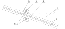
Fig. 2 is the utility model cushion cap top plane view.
In figure, 1-railway center line, the firm structure pier of 2-both legs, 3-cushion cap, 4-aqueduct, 5-pile foundation, 6-pipe safety sideline.
The specific embodiment
Below in conjunction with the specific embodiment, the utility model is described in detail.
Common Railway Bridges And Piers structure has been constructed pile foundation, cushion cap and pier shaft from bottom to top successively, and the general all bridge piers of paragraph all adopt identical form of structure, bridge pier from top to bottom sectional dimension substantially equate the standard overall structure of (or variation is very little).Once railway and existing pipeline intersect, especially run into that low-angle intersects and bridge hole across the limited situation of arrangement requirement adjusting range, for crossing over existing pipeline Railway Bridges And Piers, cannot adopt standard overall structure.The utility model by with bridge under the bridge pier of whole shape of existing buildings low-angle intersection be adjusted into the firm wall pier of both legs, pile foundation 5 and the cushion cap 3 on it are arranged to two groups, be separately positioned on the both sides of existing buildings under bridge, and guarantee that it is in outside, pipe safety sideline, the firm wall pier of both legs center bottom fovea superior, forms two lateral braces, is placed on both sides cushion cap 3, two lateral braces are outward-dipping from bottom to top, and inclined degree adjusts according to the distance between duct width and safe sideline.
Construction sequence is as follows:
(1) dig and visit existing pipeline (or other linear structure) position, elevation and trend, define its safe distance;
(2) construction stake basis;
(3) should properly protect during bearing platform construction, prevent that cushion cap excavation from causing structure base unstability;
(4) backfill cushion cap foundation ditch compacting;
(5) set up the cast-in-place construction that carries out both legs rigid frame bridge after support and template;
It is cited that content of the present utility model is not limited to embodiment, and the conversion of any equivalence that those of ordinary skills take technical solutions of the utility model by reading the utility model manual, is claim of the present utility model and contains.
Claims (2)
1. low-angle is crossed over a both legs rigid frame bridge pier structure for existing buildings, has constructed successively pile foundation (5), cushion cap (3) and firm structure pier from bottom to top, it is characterized in that:
Described pile foundation (5) and the cushion cap on it (3) are provided with two groups, are separately positioned on the both sides of existing buildings under bridge;
Described firm structure pier is the firm structure piers of both legs (2), and top is whole, and center bottom fovea superior forms two lateral braces, is placed on both sides cushion cap (3).
2. the both legs rigid frame bridge pier structure that a kind of low-angle according to claim 1 is crossed over existing buildings, is characterized in that:
Two lateral braces of the firm structure piers of described both legs (2) are outward-dipping from top to bottom.
Priority Applications (1)
| Application Number | Priority Date | Filing Date | Title |
|---|---|---|---|
| CN201320643968.7U CN203530835U (en) | 2013-10-18 | 2013-10-18 | Double-leg rigid-frame pier structure spanning existing building at small angle |
Applications Claiming Priority (1)
| Application Number | Priority Date | Filing Date | Title |
|---|---|---|---|
| CN201320643968.7U CN203530835U (en) | 2013-10-18 | 2013-10-18 | Double-leg rigid-frame pier structure spanning existing building at small angle |
Publications (1)
| Publication Number | Publication Date |
|---|---|
| CN203530835U true CN203530835U (en) | 2014-04-09 |
Family
ID=50417060
Family Applications (1)
| Application Number | Title | Priority Date | Filing Date |
|---|---|---|---|
| CN201320643968.7U Expired - Lifetime CN203530835U (en) | 2013-10-18 | 2013-10-18 | Double-leg rigid-frame pier structure spanning existing building at small angle |
Country Status (1)
| Country | Link |
|---|---|
| CN (1) | CN203530835U (en) |
Cited By (1)
| Publication number | Priority date | Publication date | Assignee | Title |
|---|---|---|---|---|
| CN109706834A (en) * | 2018-12-14 | 2019-05-03 | 中交城乡建设规划设计研究院有限公司 | Across underground structure highway bridge basis |
-
2013
- 2013-10-18 CN CN201320643968.7U patent/CN203530835U/en not_active Expired - Lifetime
Cited By (1)
| Publication number | Priority date | Publication date | Assignee | Title |
|---|---|---|---|---|
| CN109706834A (en) * | 2018-12-14 | 2019-05-03 | 中交城乡建设规划设计研究院有限公司 | Across underground structure highway bridge basis |
Similar Documents
| Publication | Publication Date | Title |
|---|---|---|
| CN205134327U (en) | Concrete diclinic props row -pile support system | |
| CN202492865U (en) | Correction device of transmission tower | |
| CN202298623U (en) | Light adjustable positioning device for steel protection barrel on sea | |
| CN104294769B (en) | A kind of piling and the construction method increasing the built bridge abutment structure of platform cap composite reinforcement | |
| CN203270461U (en) | Bailey beam support without buttress in soft foundation | |
| CN106088120B (en) | A kind of cofferdam decentralization construction method | |
| CN205530262U (en) | Adjust timing frame of steel tube column stake position among half reverse construction | |
| CN105133484B (en) | A kind of part earth anchor higher-lower tower cable-stayed bridge structure | |
| CN202450485U (en) | Sheet pile-reinforced flood control wall | |
| CN202401398U (en) | Construction steel pipe bailey beam support in soft foundation | |
| CN104195956A (en) | Scaffolding type water area continuous beam cast-in-situ supporting frame and erection method thereof | |
| CN203530835U (en) | Double-leg rigid-frame pier structure spanning existing building at small angle | |
| CN204097889U (en) | A kind of piling and the built bridge abutment structure of increase platform cap composite reinforcement | |
| CN207392053U (en) | A kind of alignment control device suitable for steel construction abnormity tower | |
| CN203625777U (en) | Adjustable wheeltrack type beam transporting vehicle on beams | |
| CN205223837U (en) | Y shape pier of belted steel pull rod | |
| CN202416252U (en) | L-shaped flood prevention retaining wall with high piles | |
| CN105804111A (en) | Unequal-length-leg offshore wind power jacket foundation and construction method thereof | |
| CN202831003U (en) | Reinforced structure of circular-shaped pile foundation of railway shallow foundation bridge | |
| CN202227354U (en) | Greening structure for high and steep concrete slopes | |
| CN204662486U (en) | Can for the mutual foundation of size tower crane conversion | |
| CN205115988U (en) | Part earth anchor height tower cable -stay bridge structure | |
| CN204626258U (en) | Suspension-pulling combined erecting device for bridge erection | |
| CN202247935U (en) | +/- 800 KV extra-high voltage direct-current large-span cast-in-place pile foundation | |
| CN203066082U (en) | Temporary trestle on edge of anchor rod support type foundation pit |
Legal Events
| Date | Code | Title | Description |
|---|---|---|---|
| C14 | Grant of patent or utility model | ||
| GR01 | Patent grant | ||
| CX01 | Expiry of patent term |
Granted publication date: 20140409 |
|
| CX01 | Expiry of patent term |