CN203514882U - Pitching two-layer lifting parking equipment - Google Patents
Pitching two-layer lifting parking equipment Download PDFInfo
- Publication number
- CN203514882U CN203514882U CN201320592117.4U CN201320592117U CN203514882U CN 203514882 U CN203514882 U CN 203514882U CN 201320592117 U CN201320592117 U CN 201320592117U CN 203514882 U CN203514882 U CN 203514882U
- Authority
- CN
- China
- Prior art keywords
- lifting arm
- column
- hinged
- ascending
- layers
- Prior art date
- Legal status (The legal status is an assumption and is not a legal conclusion. Google has not performed a legal analysis and makes no representation as to the accuracy of the status listed.)
- Expired - Fee Related
Links
Images


Abstract
The utility model discloses pitching two-layer lifting parking equipment. The parking equipment comprises two stand columns. The bottoms of the stand columns are hinged to one ends of rockers. The upper portions of the stand columns are hinged to one ends of piston rods. One ends of driving cylinders are hinged to the middle portions of the rockers. Dragging idler wheels are arranged at the other ends of the rockers. The two dragging idler wheels are matched with the bottoms of two lifting arms respectively in a rolling mode to drag the lifting arms to move vertically. A parking plate is arranged between the two lifting arms. Guide plates which are perpendicularly connected with the lifting arms are arranged at one ends of the lifting arms and are hinged to one ends of connecting arms through rotating shafts. Guide wheels matched with guide grooves in the stand columns are arranged on the rotating shafts. The other ends of the connecting rods are also hinged to the middle portions of the rockers. The driving cylinders are connected with driving pumps to drive the rockers to swing around the bottoms of the stand columns. Vertical moving of the two lifting arms is achieved through guide of the guide wheels at one ends of the lifting arms and drag of the dragging idler wheels at the other ends of the rockers. The pitching two-layer lifting parking equipment has the advantages of being simple in structure, convenient to use, safe, reliable and capable of saving space.
Description
Technical field
The utility model relates to a kind of parking apparatus, is specifically related to two layers of ascending and descending parking device of a kind of pitching type.
Background technology
Along with automobile consumption constantly increases, city parking difficulty becomes the thorny problem that various places face, setting up three-dimensional parking device is to solve the static effective way of stopping in city, a large amount of parking systems has been set up in a national line city at present, and mechanical type three-dimensional parking garage is also being set up successively in two, three line cities.In the machinery garage of setting up, the lifting of vehicle generally adopts the lift platform of fixed platform lifting or car type.Yet also there are at present many units or family to have bicycle garage parking, an automobile can only be parked in these garage parkings, increase along with its underwriting fee amount, there are many families all to have two automobiles, the existing garage parking of many units also can not meet the needs of parking, is therefore necessary existing bicycle garage parking to improve.
Utility model content
The purpose of this utility model is to overcome the defect existing in prior art, and a kind of easy bicycle garage parking equipment in the capacity expansion is provided, and makes existing bicycle garage parking can park two layers of ascending and descending parking device of pitching type of two automobiles.
For achieving the above object, the technical solution of the utility model is two layers of ascending and descending parking device of a kind of pitching type of design, it is characterized in that, this parking apparatus at least includes two root posts, the bottom of column and one end of rocking bar are hinged, one end of the top of column and piston rod or driving cylinder is hinged, the other end of driving cylinder or piston rod and the middle part of rocking bar are hinged, at the other end of rocking bar, be provided with and drag roller, at two, drag and between roller, be provided with connecting leg, two drag roller and coordinate for dragging lifting arm and move up and down with the bottom rolling of two lifting arms respectively, between two lifting arms, be provided with parking plate, near lifting arm one end, be provided with and lifting arm guide strip connected vertically, guide strip is hinged by one end of rotating shaft and connecting rod, rotating shaft is provided with the directive wheel matching with gathering sill on column, the other end of connecting rod is also hinged with the middle part of rocking bar, driving cylinder swings around the bottom of column by be connected drive rocker with driving pump, and the guiding and the rocking bar other end that move up and down by lifting arm one end directive wheel of two lifting arms drag dragging of roller.
For the ease of column is firmly fixed on the ground, be convenient to install fixed drive pump and control box simultaneously, preferred technical scheme is, surrounding in described column bottom is provided with U-shaped framework, U-shaped framework comprises left and right basic part and the link being connected with column, a side at link is also connected with driving pump support, at the opposite side of link, is also connected with operating case support, on operating case support, is connected with operating case.
For the ease of column is firmly fixed on the ground, be convenient to directive wheel coordinates with the rolling between column simultaneously, further preferred technical scheme is, described column comprises that cross section is the section bar of C shape, in the bottom of section bar, be provided with winning in succession and strengthening gusset of being connected with U-shaped framework, a side in section bar outside is connected with cladding plate, opposite side in section bar outside is connected with that rocking arm is won in succession, the junction plate of limit switch baffle plate and driving cylinder or piston rod, the back side in C shape section bar open side is provided with stiffener, and wherein gathering sill one side of C shape section bar is rolled and coordinated with directive wheel.
For the ease of saving the space in garage, be convenient to storing cycle on parking plate simultaneously, further preferred technical scheme also has, front end at described lifting arm is provided with the forearm that can upwards turn up, forearm is connected with lifting arm by connector and bearing pin, and forearm is fixedly connected with connector, and the end of forearm is ramped shaped, between two forearms, be provided with checkered plates, between the slope section of two forearms, be provided with checkered plates.
For stopping of the vehicle stabilization after making to be raised, and the driving force of power will be stopped promoting, further preferred technical scheme also has, on described lifting arm, be provided with locking hook driver, locking hook driver is linked up with handing-over by push rod and locking, and locking hook is connected with below lifting arm by rotating shaft and hook bearing.
In order to prevent the slip of vehicle in lifting process, improve the support force of parking plate simultaneously, further preferred technical scheme also has, described parking plate is checkered plates, checkered plates is connected with lifting arm by the junction plate of checkered plates, below checkered plates, be provided with the some square tubes that are connected with lifting arm, parking plate is connected with checkered plates between the lifting arm of guide strip one side, and checkered plates is the folding laying of zigzag.
Wheel is skidded off by the place ahead of parking plate in order to prevent from stopping, and further preferred technical scheme also has, and the one end coordinating with column at described lifting arm is provided with gear wheel frame, and gear wheel support is connected with the gear wheel rack connecting plate that is arranged on lifting arm end.
In order to make than thering is enough intensity, be convenient to rocking arm and column simultaneously, the connection of driver part and driven parts, coordinate, further preferred technical scheme also has, described rocking arm is rhs-structure, one end of square tube is won in succession hinged by the rocking arm on hinge and column, in the both sides at square tube middle part, being provided with the driving being connected with piston rod or driving cylinder wins in succession, a side at square tube middle part is also provided with connecting rod and wins in succession, connecting rod is won in succession by bearing pin and rod hinge connection, in a side of the square tube other end, be also provided with and drag roller supporting plate, be connected with and drag roller junction plate dragging on roller supporting plate, drag roller junction plate by rotating shaft with drag roller and be connected, on roller junction plate, be also provided with hook look mandrel dragging, hook look mandrel and shaft parallel, and coordinate with locking hook.
In order better to control the range of lifting arm, and the locking unlocking action of controlling locking hook, further preferred technical scheme also has, on described rocking arm, be also provided with the limit switch corresponding with limit switch baffle position, on lifting arm, be provided with the locking hook open-close on-off corresponding with locking hook position.
For the vibrations that prevent that lifting arm from producing vehicle when dropping to terminal, further preferred technical scheme also has, and on ground corresponding to described lifting arm, is provided with beam.
Advantage of the present utility model and beneficial effect are: two layers of ascending and descending parking device of this pitching type are by hydraulic cylinder and piston rod, stretching motion under the driving of driving pump, come drive rocker to swing up and down, the swing of doing can drag moving up and down of lifting arm, one end of lifting arm is the scroll-up/down on column by directive wheel, can make lifting arm be a less inclination angle oscilaltion campaign, between two lifting arms, parking plate is housed, so just can realize simply the elevating movement of vehicle, make the garage that originally can only park an automobile can park two automobiles simultaneously.This equipment has simple in structure, easy to use, safe and reliable, saves space, is a kind of garage capacity-enlargement technology scheme of small investment instant effect.
Accompanying drawing explanation
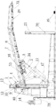
Fig. 1 is the structural representation of two layers of ascending and descending parking device of pitching type;
Fig. 2 is the top view of Fig. 1;
Fig. 3 is the structural representation front view of Fig. 1 central post and column installation frame;
Fig. 4 is the top view of Fig. 3;
Fig. 5 is that in Fig. 1, the mounting structure master of lifting arm and parking plate looks schematic diagram
Fig. 6 is the top view of Fig. 5;
Fig. 7 is that the master of Fig. 1 central post and rocking bar, piston rod and driving cylinder, connecting rod syndeton looks schematic diagram;
Fig. 8 is the top view of Fig. 7;
Fig. 9 is the partial enlarged drawing at A position in Fig. 8;
Figure 10 is the partial enlarged drawing at locking hook position in Fig. 1.
In figure: 1, column; 2, rocking bar; 3, piston rod; 4, driving cylinder; 5, drag roller; 6, connecting leg; 7, lifting arm; 8, parking plate; 9, guide strip; 10, rotating shaft; 11, connecting rod; 12, gathering sill; 13, directive wheel; 14, driving pump; 15, U-shaped framework; 16, left basic part; 17, right basic part; 18, link; 19, driving pump support; 20, operating case support; 21, operating case; 22, win in succession; 23, cladding plate; 24, rocking arm is won in succession; 25, limit switch baffle plate; 26, junction plate; 27, stiffener; 28, forearm; 29, connector; 30, bearing pin; 31, checkered plates; 32, checkered plates; 33, locking hook driver; 34, push rod; 35, locking hook; 36, rotating shaft and hook bearing; 37, the junction plate of checkered plates; 38, square tube; 39, checkered plates; 40, gear wheel frame; 41, gear wheel rack connecting plate; 42, drive and win in succession; 43, connecting rod is won in succession; 44, drag roller supporting plate; 45, drag roller junction plate; 46, hook look mandrel; 47, limit switch; 48, locking hook open-close on-off; 49, beam.
The specific embodiment
Below in conjunction with drawings and Examples, the specific embodiment of the present utility model is further described.Following examples are only for the technical solution of the utility model is more clearly described, and can not limit protection domain of the present utility model with this.
As shown in Fig. 1 to 2, the utility model is two layers of ascending and descending parking device of a kind of pitching type, this parking apparatus includes two root posts 1, one end of the bottom of column 1 and rocking bar 2 is hinged, one end of the top of column 1 and piston rod 3 is hinged, coordinate one end of driving cylinder 4 and the middle part of rocking bar 2 hinged with piston rod 3, at the other end of rocking bar 2, be provided with and drag roller 5, at two, drag and between roller 5, be provided with connecting leg 6, two drag roller 5 and coordinate for dragging lifting arm and move up and down with the bottom rolling of two lifting arms 7 respectively, between two lifting arms 6, be provided with parking plate 8, near lifting arm 7 one end, be provided with and lifting arm guide strip 9 connected vertically, guide strip 9 is hinged with one end of connecting rod 11 by rotating shaft 10, in rotating shaft 10, be provided with the directive wheel 13 matching with gathering sill 12 on column 1, the other end of connecting rod 11 is also hinged with the middle part of rocking bar 2, driving cylinder 4 swings around the bottom of column 1 by being connected drive rocker 2 with driving pump 14, the guiding and rocking bar 2 other ends that move up and down by lifting arm 7 one end directive wheels 13 of two lifting arms 7 drag dragging of roller 5, the vehicle being docked on parking plate 8 can be risen or settle out.
In the utility model for the ease of column is firmly fixed on the ground, be convenient to install fixed drive pump and control box simultaneously, preferred embodiment is, as shown in Figs. 3-4, surrounding in column 1 bottom is provided with U-shaped framework 15, U-shaped framework 15 comprises left and right basic part 16,17 and the link 18 being connected with column 1, a side at link 18 is also connected with driving pump support 19, opposite side at link 18 is also connected with operating case support 20, is connected with operating case 21 on operating case support 20.
In the utility model for the ease of column is firmly fixed on the ground, be convenient to directive wheel coordinates with the rolling between column simultaneously, further preferred embodiment is, as shown in Figs. 3-4, column 1 comprises that cross section is the section bar of C shape, in the bottom of section bar, be provided be connected with U-shaped framework 15 win 22 and strengthen gusset in succession, a side in section bar outside is connected with cladding plate 23, opposite side in section bar outside is connected with rocking arm and wins 24 in succession, the junction plate 26 of limit switch baffle plate 25 and piston rod, the back side in C shape section bar open side is provided with stiffener 27, wherein gathering sill 12 1 sides of C shape section bar are rolled and are coordinated with directive wheel 13.
In the utility model for the ease of saving the space in garage, be convenient to storing cycle on parking plate simultaneously, further preferred embodiment also has, as shown in FIG. 5 and 6, at the front end of lifting arm 6, be provided with the forearm 28 that can upwards turn up, forearm 28 is connected with lifting arm 6 by connector 29 and bearing pin 30, forearm 28 is fixedly connected with connector 29, the end of forearm 28 is ramped shaped, between two forearms 28, is provided with checkered plates 31, is provided with checkered plates 32 between the slope section of two forearms 28.
Stopping for the vehicle stabilization after making to be raised in the utility model, and the driving force of power will be stopped promoting, preferred embodiment also has, as shown in figure 10, on lifting arm 6, be provided with locking hook driver 33, locking hook driver 33 is linked up with 35 handing-over by push rod 34 and locking, and locking hook 35 is connected with below lifting arm 6 by rotating shaft and hook bearing 36.
In the utility model in order to prevent the slip of vehicle in lifting process, improve the support force of parking plate simultaneously, further preferred embodiment also has, as shown in FIG. 5 and 6, parking plate 8 is checkered plates, and checkered plates is connected with lifting arm 6 by the junction plate 37 of checkered plates, is provided with the some square tubes 38 that are connected with lifting arm 6 below checkered plates, parking plate 8 is connected with checkered plates 39 between the lifting arm 6 of guide strip 9 one sides, and checkered plates 39 is the folding laying of zigzag.
In the utility model, wheel is skidded off by the place ahead of parking plate in order to prevent from stopping, further preferred embodiment also has, as shown in Figure 1, 2, the one end coordinating with column 1 at lifting arm 6 is provided with gear wheel frame 40, and gear wheel support 40 is connected with the gear wheel rack connecting plate 41 that is arranged on lifting arm 6 ends.
In the utility model in order to make than thering is enough intensity, be convenient to rocking arm and column simultaneously, the connection of driver part and driven parts, coordinate, further preferred embodiment also has, as Fig. 7, shown in 8, rocking arm 2 is rhs-structure, one end of square tube is won in succession 24 hinged by the rocking arm on hinge and column 1, in the both sides at square tube middle part, be provided with the driving being connected with driving cylinder 4 and win 42 in succession, a side at square tube middle part is also provided with connecting rod and wins 43 in succession, it is 43 hinged by bearing pin and connecting rod 11 that connecting rod is won in succession, in a side of the square tube other end, be also provided with and drag roller supporting plate 44, be connected with and drag roller junction plate 45 dragging on roller supporting plate 44, drag roller junction plate 45 by rotating shaft 10 with drag roller 5 and be connected, on roller junction plate 45, be also provided with hook look mandrel 46 dragging, hook look mandrel 46 is parallel with rotating shaft 10, and coordinate and be used for locking hook with locking hook 35.
In the utility model in order better to control the range of lifting arm, and the locking unlocking action of controlling locking hook, further preferred embodiment also has, as shown in Figure 1, on rocking arm 2, be also provided with the limit switch 47 corresponding with limit switch baffle plate 25 positions, on lifting arm 6, be provided with the locking hook open-close on-off 48 corresponding with locking hook 35 positions.
In the utility model, be the vibrations in order to prevent that lifting arm from producing vehicle when dropping to terminal, further preferred embodiment also has, and is provided with beam 49 on the ground of lifting arm 6 correspondences.
The operating principle of two layers of ascending and descending parking device of the utility model pitching type is, as shown in Figure 1, when parking plate is positioned at ground, vehicle can directly be moored on parking plate, by the action button primer fluid press pump on operating case, make the relative hydraulic cylinder of piston rod, when shrinking gradually between piston rod and hydraulic cylinder, hydraulic cylinder pulls rocking bar upwards to lift, one end of rocking bar holds up lifting arm by dragging roller, the directive wheel that is hinged on lifting arm one end scrolls up vehicle is upwards lifted along the gathering sill on column, when giving rise to setting position, under the control of limit switch, driving pump quits work, between piston rod and hydraulic cylinder, relative motion stops, simultaneously under the driving of locking hook driver, locking fastened with hook is to hook look mandrel, under the state now disappearing in driving force, hook links together lifting arm and rocking bar, then the forearm of lifting arm upwards can be dug to save the space in garage, under this state, can under the parking plate having risen, park again an automobile.When the vehicle on being docked in parking plate need to be gone on a journey, first the vehicle of below is shifted out, then press start button, first make hook and rocking bar break off relations, then start driving pump, piston rod is stretched out gradually from hydraulic cylinder, lifting arm is put down by dragging roller in one end of rocking bar, the directive wheel that is hinged on lifting arm one end rolls vehicle is placed into ground downwards downwards along the gathering sill on column, when lifting arm is placed to behind ground, under the control of limit switch, driving pump quits work, again forearm is folded flat downwards, now just the vehicle on parking plate can be rolled away from.
The above is only preferred embodiment of the present utility model; should be understood that; for those skilled in the art; do not departing under the prerequisite of the utility model know-why; can also make some improvements and modifications, these improvements and modifications also should be considered as protection domain of the present utility model.
Claims (10)
1. two layers of ascending and descending parking device of a pitching type, it is characterized in that, this parking apparatus at least includes two root posts, the bottom of column and one end of rocking bar are hinged, one end of the top of column and piston rod or driving cylinder is hinged, the other end of driving cylinder or piston rod and the middle part of rocking bar are hinged, at the other end of rocking bar, be provided with and drag roller, at two, drag and between roller, be provided with connecting leg, two drag roller and coordinate for dragging lifting arm and move up and down with the bottom rolling of two lifting arms respectively, between two lifting arms, be provided with parking plate, near lifting arm one end, be provided with and lifting arm guide strip connected vertically, guide strip is hinged by one end of rotating shaft and connecting rod, rotating shaft is provided with the directive wheel matching with gathering sill on column, the other end of connecting rod is also hinged with the middle part of rocking bar, driving cylinder swings around the bottom of column by be connected drive rocker with driving pump, and the guiding and the rocking bar other end that move up and down by lifting arm one end directive wheel of two lifting arms drag dragging of roller.
2. two layers of ascending and descending parking device of pitching type as claimed in claim 1, it is characterized in that, surrounding in described column bottom is provided with U-shaped framework, U-shaped framework comprises left and right basic part and the link being connected with column, a side at link is also connected with driving pump support, opposite side at link is also connected with operating case support, on operating case support, is connected with operating case.
3. two layers of ascending and descending parking device of pitching type as claimed in claim 2, it is characterized in that, described column comprises that cross section is the section bar of C shape, in the bottom of section bar, be provided with winning in succession and strengthening gusset of being connected with U-shaped framework, a side in section bar outside is connected with cladding plate, opposite side in section bar outside is connected with that rocking arm is won in succession, the junction plate of limit switch baffle plate and driving cylinder or piston rod, at the back side of C shape section bar open side, is provided with stiffener, and wherein gathering sill one side of C shape section bar coordinates with directive wheel rolling.
4. two layers of ascending and descending parking device of pitching type as claimed in claim 3, it is characterized in that, front end at described lifting arm is provided with the forearm that can upwards turn up, forearm is connected with lifting arm by connector and bearing pin, forearm is fixedly connected with connector, the end of forearm is ramped shaped, between two forearms, is provided with checkered plates, between the slope section of two forearms, is provided with checkered plates.
5. two layers of ascending and descending parking device of pitching type as claimed in claim 4, it is characterized in that, on described lifting arm, be provided with locking hook driver, locking hook driver is linked up with handing-over by push rod and locking, and locking hook is connected with below lifting arm by rotating shaft and hook bearing.
6. two layers of ascending and descending parking device of pitching type as claimed in claim 5, it is characterized in that, described parking plate is checkered plates, checkered plates is connected with lifting arm by the junction plate of checkered plates, below checkered plates, be provided with the some square tubes that are connected with lifting arm, parking plate is connected with checkered plates between the lifting arm of guide strip one side, and checkered plates is the folding laying of zigzag.
7. two layers of ascending and descending parking device of pitching type as claimed in claim 6, is characterized in that, the one end coordinating with column at described lifting arm is provided with gear wheel frame, and gear wheel support is connected with the gear wheel rack connecting plate that is arranged on lifting arm end.
8. two layers of ascending and descending parking device of pitching type as claimed in claim 7, it is characterized in that, described rocking arm is rhs-structure, one end of square tube is won in succession hinged by the rocking arm on hinge and column, in the both sides at square tube middle part, being provided with the driving being connected with piston rod or driving cylinder wins in succession, a side at square tube middle part is also provided with connecting rod and wins in succession, connecting rod is won in succession by bearing pin and rod hinge connection, in a side of the square tube other end, be also provided with and drag roller supporting plate, be connected with and drag roller junction plate dragging on roller supporting plate, drag roller junction plate by rotating shaft with drag roller and be connected, on roller junction plate, be also provided with hook look mandrel dragging, hook look mandrel and shaft parallel, and coordinate with locking hook.
9. two layers of ascending and descending parking device of pitching type as claimed in claim 8, it is characterized in that, on described rocking arm, be also provided with the limit switch corresponding with limit switch baffle position, on lifting arm, be provided with the locking hook open-close on-off corresponding with locking hook position.
10. two layers of ascending and descending parking device of pitching type as in one of claimed in any of claims 1 to 9, is characterized in that, on ground corresponding to described lifting arm, are provided with beam.
Priority Applications (1)
| Application Number | Priority Date | Filing Date | Title |
|---|---|---|---|
| CN201320592117.4U CN203514882U (en) | 2013-09-24 | 2013-09-24 | Pitching two-layer lifting parking equipment |
Applications Claiming Priority (1)
| Application Number | Priority Date | Filing Date | Title |
|---|---|---|---|
| CN201320592117.4U CN203514882U (en) | 2013-09-24 | 2013-09-24 | Pitching two-layer lifting parking equipment |
Publications (1)
| Publication Number | Publication Date |
|---|---|
| CN203514882U true CN203514882U (en) | 2014-04-02 |
Family
ID=50373836
Family Applications (1)
| Application Number | Title | Priority Date | Filing Date |
|---|---|---|---|
| CN201320592117.4U Expired - Fee Related CN203514882U (en) | 2013-09-24 | 2013-09-24 | Pitching two-layer lifting parking equipment |
Country Status (1)
| Country | Link |
|---|---|
| CN (1) | CN203514882U (en) |
Cited By (3)
| Publication number | Priority date | Publication date | Assignee | Title |
|---|---|---|---|---|
| CN103603516A (en) * | 2013-09-24 | 2014-02-26 | 江苏启良停车设备有限公司 | Pitching type two-layer lift parking device |
| CN104005586A (en) * | 2014-05-30 | 2014-08-27 | 山东同力达智能机械有限公司 | Anti-dropping device for three-dimensional garage |
| CN109488066A (en) * | 2019-01-07 | 2019-03-19 | 天津城建大学 | A kind of collapsible parking device |
-
2013
- 2013-09-24 CN CN201320592117.4U patent/CN203514882U/en not_active Expired - Fee Related
Cited By (3)
| Publication number | Priority date | Publication date | Assignee | Title |
|---|---|---|---|---|
| CN103603516A (en) * | 2013-09-24 | 2014-02-26 | 江苏启良停车设备有限公司 | Pitching type two-layer lift parking device |
| CN104005586A (en) * | 2014-05-30 | 2014-08-27 | 山东同力达智能机械有限公司 | Anti-dropping device for three-dimensional garage |
| CN109488066A (en) * | 2019-01-07 | 2019-03-19 | 天津城建大学 | A kind of collapsible parking device |
Similar Documents
| Publication | Publication Date | Title |
|---|---|---|
| CN103603516A (en) | Pitching type two-layer lift parking device | |
| CN202899694U (en) | Front-driving-type double-layer steroscopic garage | |
| CN204920373U (en) | Utilize stereo garage in road upper portion space | |
| CN206722494U (en) | A kind of small-sized efficient side coil up-down cross sliding type multi-storied garage | |
| CN203514882U (en) | Pitching two-layer lifting parking equipment | |
| CN107901769A (en) | It is a kind of that there is anti-pitfall and the high new-energy automobile of generating efficiency | |
| CN204960426U (en) | Lifting and horizontally moving type stereo garage | |
| CN105937316B (en) | Bilayer is without avoidance elevator for parked vehicles and parking apparatus | |
| CN105781173A (en) | Foldable single parking space device | |
| CN203344668U (en) | Vertically track rolling on and off device for road-rail vehicle | |
| CN203175100U (en) | Rail type simple hydraulic lift parking device | |
| CN101597966B (en) | Three-dimensional garage with convenient parking | |
| CN202831711U (en) | Transverse parking device | |
| CN105239811B (en) | A kind of carrier dolly with the device that microlitre edges down | |
| CN103061550B (en) | Single-side hydraulic drive type space framework parking space | |
| CN203531455U (en) | Double-shear-fork type lifting parking device | |
| CN207160688U (en) | A kind of double-deck stereo Novel garage | |
| CN2849038Y (en) | Small size double layer hydraulic parking device | |
| CN202990499U (en) | Double-portal elevated parking garage | |
| CN203285095U (en) | Novel simple rotatable lifting parking equipment | |
| CN205113108U (en) | On -vehicle slide rail folding vehicle lifting mechanism | |
| CN203583952U (en) | Novel simple laterally-swaying lifting-type stereo garage | |
| CN209244351U (en) | A kind of grating type parking systems | |
| CN202706613U (en) | Double-layer parking space | |
| CN207513262U (en) | A kind of double-deck stereo parking device |
Legal Events
| Date | Code | Title | Description |
|---|---|---|---|
| C14 | Grant of patent or utility model | ||
| GR01 | Patent grant | ||
| CF01 | Termination of patent right due to non-payment of annual fee | ||
| CF01 | Termination of patent right due to non-payment of annual fee |
Granted publication date: 20140402 Termination date: 20180924 |