CN203391204U - Display die - Google Patents
Display die Download PDFInfo
- Publication number
- CN203391204U CN203391204U CN201320469877.6U CN201320469877U CN203391204U CN 203391204 U CN203391204 U CN 203391204U CN 201320469877 U CN201320469877 U CN 201320469877U CN 203391204 U CN203391204 U CN 203391204U
- Authority
- CN
- China
- Prior art keywords
- insulation board
- thermal insulation
- core
- cope match
- mouldboard
- Prior art date
- Legal status (The legal status is an assumption and is not a legal conclusion. Google has not performed a legal analysis and makes no representation as to the accuracy of the status listed.)
- Expired - Fee Related
Links
Images
Abstract
The utility model discloses a display die. The display die comprises a top board, an upper insulation board, an upper mouldboard, a lower mouldboard, cores, a lower insulation board and a bottom board, wherein the upper insulation board is arranged below the top board; the upper mouldboard is arranged on the lower surface of the upper insulation board; the lower mouldboard is arranged on the lower surface of the upper mouldboard; cavities for casting a display are defined between the upper mouldboard and the lower mouldboard; the cores are arranged between the upper mouldboard and the lower mouldboard; hanging platforms are arranged on one sides of the lower ends of the cores and straight planes are arranged on the other sides of the lower ends of the cores; the lower insulation board is arranged on the lower surface of the lower mouldboard; the bottom board is arranged below the lower insulation board. The die has the beneficial effects that the hanging platforms and the planes are arranged on the two sides of the lower ends of the cores respectively, thus avoiding reverse installation; fool-proofing can be effectively carried out during die filling and the die can not be pressed, thus improving the die quality.
Description
Technical field
The utility model relates to a kind of mould, especially a kind of display mould.
Background technology
Injection mold is the important process equipment of producing various industrial products, along with plastic mould design industry developing rapidly and plasthetics aviation, boat too, the applying of the industrial department such as electronics, machinery, boats and ships and automobile, product is more and more higher to the requirement of mould, and traditional plastic mould method for designing cannot adapt to model change and propose high-quality requirement.Computer aided engineering technology become these weak links in plastic cement products exploitation, Design of Dies and product processing the most effectively by way of.
Summary of the invention
The utility model provides a kind of display mould, and described mould comprises: top board; Upper thermal insulation board, described upper thermal insulation board is located at the below of described top board; Cope match plate, described cope match plate is located on the lower surface of described upper thermal insulation board; Lower template, described lower template is located on the lower surface of described cope match plate, limits the die cavity of casting display between wherein said cope match plate and described lower template; Core, described core is located between described cope match plate and lower template, and lower end one side of described core is provided with hanging platform, and opposite side is straight plane; Lower thermal insulation board, described lower thermal insulation board is located on the lower surface of described lower template; Base plate, described base plate is located at the below of described lower thermal insulation board.
According to the mould of the utility model embodiment, by both sides, core lower end being made as to hanging platform one side plane on one side, avoid also filling conversely.The utility model carries out fool proof at dress in mould effectively, can pressing mold, improved die quality.If in display Design of Dies, hanging platform is all designed on these mould parts both sides, will cause at dress often anti-loadedly during mould, causes mould to damage by pressure.
Preferably, described hanging platform is located at the right side of core lower end.
Preferably, described core is two, corresponds respectively to two die cavities in left and right.
Preferably, the hanging platform of a left side core is positioned at the left side of left side core; The hanging platform of right side core is positioned at the right side of right side core.
Preferably, described two cores are relative on left and right directions.
Preferably, described lower template has the concave station corresponding with described hanging platform.
Preferably, described upper thermal insulation board, described cope match plate, described lower template, described lower thermal insulation board and described base plate removably link together by bolt.
Preferably, described upper thermal insulation board, described cope match plate, described lower template, described lower thermal insulation board and described base plate removably link together by a plurality of described bolts.
Preferably, a plurality of described bolts are positioned on the first circumference.
Preferably, a plurality of described bolts are distributed on described the first circumference equally spacedly.
Accompanying drawing explanation
Above-mentioned and/or additional aspect of the present utility model and advantage accompanying drawing below combination obviously and is easily understood becoming the description of embodiment, wherein:
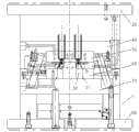
Fig. 1 is according to the structural representation of the mould of the utility model embodiment.
Description of reference numerals: display mould 1, top board 20, core 30, hanging platform 31, upper thermal insulation board 40, cope match plate 50, lower template 60, lower thermal insulation board 70, base plate 80.
The specific embodiment
Describe embodiment of the present utility model below in detail, the example of described embodiment is shown in the drawings, and wherein same or similar label represents same or similar element or has the element of identical or similar functions from start to finish.Below by the embodiment being described with reference to the drawings, be exemplary, only for explaining the utility model, and can not be interpreted as restriction of the present utility model.
Below with reference to Fig. 1, describe according to the display mould 1 of the utility model embodiment.As shown in Figure 1, according to the display mould 1 of the utility model embodiment, comprise top board 20, core 30, hanging platform 31, upper thermal insulation board 40, cope match plate 50, lower template 60, lower thermal insulation board 70, base plate 80.
Upper thermal insulation board 40 is located at the below of described top board 20; Cope match plate 50 is located on the lower surface of described upper thermal insulation board 40; Lower template 60 is located on the lower surface of described cope match plate 50, limits the die cavity of casting display between wherein said cope match plate 50 and described lower template 60; Core 30 is located between described cope match plate 50 and lower template 60, and described core 30 lower end one side is provided with hanging platform 31, and opposite side is straight plane; Lower thermal insulation board 70 is located on the lower surface of described lower template 60; Base plate 80 is located at the below of described lower thermal insulation board 70.
According to the mould of the utility model embodiment, by core 30 both sides, lower end being made as to hanging platform 31 one side planes on one side, avoid also filling conversely.The utility model carries out fool proof at dress in mould effectively, can pressing mold, improved die quality.
Preferably, described hanging platform 31 is located at the right side of core 30 lower ends.Preferably, described core 30 is two, corresponds respectively to two die cavities in left and right.Can make thus the production efficiency of mould improve.
Preferably, the hanging platform 31 of a left side core 30 is positioned at the left side of left side core 30; The hanging platform 31 of right side core 30 is positioned at core 30 right side, right side.Described two cores 30 are relative on left and right directions.Can make thus the structure of mould 1 more reasonable.
Preferably, described lower template 60 has the concave station corresponding with described hanging platform 31.
Preferably, described upper thermal insulation board 40, described cope match plate 50, described lower template 60, described lower thermal insulation board 70 and described base plate 80 are circular.Described upper thermal insulation board 40, described cope match plate 50, described lower template 60, described lower thermal insulation board 70 and described base plate 80 removably link together by a plurality of described bolts.
Advantageously, a plurality of described bolts are positioned on the first circumference.Preferably, a plurality of described bolts are distributed on described the first circumference equally spacedly.Can improve the assembly precision of display mould 1 thus.
In the description of this description, the description of reference term " embodiment ", " some embodiment ", " example ", " concrete example " or " some examples " etc. means to be contained at least one embodiment of the present utility model or example in conjunction with specific features, structure, material or the feature of this embodiment or example description.In this manual, the schematic statement of above-mentioned term is not necessarily referred to identical embodiment or example.And the specific features of description, structure, material or feature can be with suitable mode combinations in any one or more embodiment or example.
Although illustrated and described embodiment of the present utility model, those having ordinary skill in the art will appreciate that: in the situation that not departing from principle of the present utility model and aim, can carry out multiple variation, modification, replacement and modification to these embodiment, scope of the present utility model is limited by claim and equivalent thereof.
Claims (10)
1. a display mould, is characterized in that, comprising:
Top board;
Upper thermal insulation board, described upper thermal insulation board is located at the below of described top board;
Cope match plate, described cope match plate is located on the lower surface of described upper thermal insulation board;
Lower template, described lower template is located on the lower surface of described cope match plate, limits the die cavity of casting display between wherein said cope match plate and described lower template;
Core, described core is located between described cope match plate and lower template, and lower end one side of described core is provided with hanging platform, and opposite side is straight plane;
Lower thermal insulation board, described lower thermal insulation board is located on the lower surface of described lower template;
Base plate, described base plate is located at the below of described lower thermal insulation board.
2. display mould according to claim 1, is characterized in that, described hanging platform is located at the right side of core lower end.
3. display mould according to claim 2, is characterized in that, described core is two, corresponds respectively to two die cavities in left and right.
4. display mould according to claim 3, is characterized in that, the hanging platform of a left side core is positioned at the left side of left side core; The hanging platform of right side core is positioned at the right side of right side core.
5. display mould according to claim 4, is characterized in that, described two cores are relative on left and right directions.
6. display mould according to claim 1, is characterized in that, described lower template has the concave station corresponding with described hanging platform.
7. display mould according to claim 1, is characterized in that, described upper thermal insulation board, described cope match plate, described lower template, described lower thermal insulation board and described base plate removably link together by bolt.
8. display mould according to claim 7, is characterized in that, described upper thermal insulation board, described cope match plate, described lower template, described lower thermal insulation board and described base plate removably link together by a plurality of described bolts.
9. display mould according to claim 8, is characterized in that, a plurality of described bolts are positioned on the first circumference.
10. display mould according to claim 9, is characterized in that, a plurality of described bolts are distributed on described the first circumference equally spacedly.
Priority Applications (1)
| Application Number | Priority Date | Filing Date | Title |
|---|---|---|---|
| CN201320469877.6U CN203391204U (en) | 2013-08-03 | 2013-08-03 | Display die |
Applications Claiming Priority (1)
| Application Number | Priority Date | Filing Date | Title |
|---|---|---|---|
| CN201320469877.6U CN203391204U (en) | 2013-08-03 | 2013-08-03 | Display die |
Publications (1)
| Publication Number | Publication Date |
|---|---|
| CN203391204U true CN203391204U (en) | 2014-01-15 |
Family
ID=49902765
Family Applications (1)
| Application Number | Title | Priority Date | Filing Date |
|---|---|---|---|
| CN201320469877.6U Expired - Fee Related CN203391204U (en) | 2013-08-03 | 2013-08-03 | Display die |
Country Status (1)
| Country | Link |
|---|---|
| CN (1) | CN203391204U (en) |
Cited By (1)
| Publication number | Priority date | Publication date | Assignee | Title |
|---|---|---|---|---|
| CN103358471A (en) * | 2013-08-03 | 2013-10-23 | 昆山市浩坤机械有限公司 | Display mold |
-
2013
- 2013-08-03 CN CN201320469877.6U patent/CN203391204U/en not_active Expired - Fee Related
Cited By (1)
| Publication number | Priority date | Publication date | Assignee | Title |
|---|---|---|---|---|
| CN103358471A (en) * | 2013-08-03 | 2013-10-23 | 昆山市浩坤机械有限公司 | Display mold |
Similar Documents
| Publication | Publication Date | Title |
|---|---|---|
| CN103171091A (en) | Die | |
| CN103171090A (en) | Die | |
| CN103192503A (en) | Die | |
| CN203391204U (en) | Display die | |
| CN103358471A (en) | Display mold | |
| CN203185594U (en) | Die | |
| CN103223711A (en) | Mold | |
| CN203391211U (en) | Plastic frame die | |
| CN203391231U (en) | Button die | |
| CN203391236U (en) | Ignition switch upper cover die | |
| CN203567046U (en) | Upper cover mold of junction box | |
| CN203391206U (en) | Display die | |
| CN203567049U (en) | Upper cover mold of junction box | |
| CN103171092A (en) | Die | |
| CN203391210U (en) | Plastic frame die | |
| CN203185593U (en) | Die | |
| CN203391216U (en) | Ignition switch upper cover die | |
| CN203157047U (en) | Mold | |
| CN203391208U (en) | Plastic frame die | |
| CN203391205U (en) | Display die | |
| CN203185595U (en) | Die | |
| CN203567052U (en) | Junction box base mold | |
| CN203391209U (en) | Plastic frame die | |
| CN203567053U (en) | Junction box base mold | |
| CN203157053U (en) | Mold |
Legal Events
| Date | Code | Title | Description |
|---|---|---|---|
| C14 | Grant of patent or utility model | ||
| GR01 | Patent grant | ||
| CF01 | Termination of patent right due to non-payment of annual fee |
Granted publication date: 20140115 Termination date: 20140803 |
|
| EXPY | Termination of patent right or utility model |