CN203391236U - Ignition switch upper cover die - Google Patents
Ignition switch upper cover die Download PDFInfo
- Publication number
- CN203391236U CN203391236U CN201320469891.6U CN201320469891U CN203391236U CN 203391236 U CN203391236 U CN 203391236U CN 201320469891 U CN201320469891 U CN 201320469891U CN 203391236 U CN203391236 U CN 203391236U
- Authority
- CN
- China
- Prior art keywords
- insulation board
- thermal insulation
- ignition switch
- top cover
- cover die
- Prior art date
- Legal status (The legal status is an assumption and is not a legal conclusion. Google has not performed a legal analysis and makes no representation as to the accuracy of the status listed.)
- Expired - Fee Related
Links
Images

Landscapes
- Moulds For Moulding Plastics Or The Like (AREA)
Abstract
The utility model discloses an ignition switch upper cover die. The die comprises a top board, an upper insulation board, an upper mouldboard, a lower mouldboard, a lower insulation board, a bottom board and a side core-pulling mechanism, wherein the upper insulation board is arranged at the lower end of the top board; the upper mouldboard is arranged on the lower surface of the upper insulation board; the lower mouldboard is arranged on the lower surface of the upper mouldboard; a cavity of an ignition switch upper cover is defined between the upper mouldboard and the lower mouldboard; the lower insulation board is arranged on the lower surface of the lower mouldboard; the bottom board is arranged at the lower end of the lower insulation board; the side core-pulling mechanism comprises a slider, a guide block and a slanted guide pillar; the slider is connected with the guide block; bosses are arranged at the upper and lower ends of the guide block; the slider is provided with slots corresponding to the bosses; the bosses and the slots are connected together in a matching manner. The die has the beneficial effects that the slider can not become loose and can not be locked due to loosening, thus improving the production efficiency and the die quality and reducing the die repair cost.
Description
Technical field
The utility model relates to a kind of mould, especially a kind of ignition switch top cover die.
Background technology
Injection mold is the important process equipment of producing various industrial products, along with plastic mould design industry developing rapidly and plasthetics aviation, boat too, the applying of the industrial department such as electronics, machinery, boats and ships and automobile, product is more and more higher to the requirement of mould, and traditional plastic mould method for designing cannot adapt to model change and propose high-quality requirement.Computer aided engineering technology become these weak links in plastic cement products exploitation, Design of Dies and product processing the most effectively by way of.
Summary of the invention
The utility model provides a kind of ignition switch top cover die, and described mould comprises: top board; Upper thermal insulation board, described upper thermal insulation board is located at the lower end of described top board; Cope match plate, described cope match plate is located on the lower surface of described upper thermal insulation board; Lower template, described lower template is located on the lower surface of described cope match plate, limits the die cavity of ignition switch upper cover between wherein said cope match plate and described lower template; Lower thermal insulation board, described lower thermal insulation board is located on the lower surface of described lower template; Base plate, described base plate is located at the lower end of described lower thermal insulation board; And side core-pulling mechanism, described side core-pulling mechanism comprises slide block, guide pad and Angle Pin, and described slide block is connected with guide pad, and the top and bottom of guide pad are equipped with boss, slide block is provided with the draw-in groove corresponding with described projection, and boss and draw-in groove cooperate together.
According to the mould of the utility model embodiment, by the upper and lower side at guide pad, two projections are set and locate, even if bolt has looseningly like this, slide block enters son and also can not become flexible up and down, stuck while causing moving.After present technique is improved, slide block can not become flexible, and can be because of sending and stuck, has improved production efficiency, has reduced the cost that repairs a die, and has improved die quality.And iff only slider bottom being positioned, top is location not, cause often becoming flexible in motion process, slide block is often stuck.
Preferably, between described slide block and guide pad, by securing member, be connected.
Preferably, described securing member is bolt.
Preferably, described bolt model is M6x21L.
Preferably, described bolt is corresponding with the center of slide block.
Preferably, described upper thermal insulation board, described cope match plate, described lower template, described lower thermal insulation board and described base plate are circular.
Preferably, described upper thermal insulation board, described cope match plate, described lower template, described lower thermal insulation board and described base plate removably link together by bolt.
Preferably, described upper thermal insulation board, described cope match plate, described lower template, described lower thermal insulation board and described base plate removably link together by a plurality of described bolts.
Preferably, a plurality of described bolts are positioned on the first circumference.
Preferably, a plurality of described bolts are distributed on described the first circumference equally spacedly.
Accompanying drawing explanation
Above-mentioned and/or additional aspect of the present utility model and advantage accompanying drawing below combination obviously and is easily understood becoming the description of embodiment, wherein:
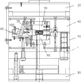
Fig. 1 is according to the structural representation of the mould of the utility model embodiment;
Fig. 2 is according to the structural representation of the mould slide block part of the utility model embodiment.
Description of reference numerals: ignition switch top cover die 1, top board 20, slide block 30, upper thermal insulation board 40, cope match plate 50, lower template 60, lower thermal insulation board 70, base plate 80, guide pad 90,91 boss, slanting guide pillar hole 92, Angle Pin 100, bolt 110.
The specific embodiment
Describe embodiment of the present utility model below in detail, the example of described embodiment is shown in the drawings, and wherein same or similar label represents same or similar element or has the element of identical or similar functions from start to finish.Below by the embodiment being described with reference to the drawings, be exemplary, only for explaining the utility model, and can not be interpreted as restriction of the present utility model.
Below with reference to Fig. 1-2, describe according to the ignition switch top cover die 1 of the utility model embodiment.As shown in Figure 1 and Figure 2, according to the ignition switch top cover die 1 of the utility model embodiment, comprise top board 20, slide block 30, upper thermal insulation board 40, cope match plate 50, lower template 60, lower thermal insulation board 70, base plate 80, guide pad 90, boss 91, slanting guide pillar hole 92, Angle Pin 100, bolt 110.
According to the mould of the utility model embodiment, by the upper and lower side at guide pad 90, two projections are set and locate, even if bolt 110 has looseningly like this, slide block 30 enters son and also can not become flexible up and down, stuck while causing moving.After present technique is improved, slide block 30 can not become flexible, and can be because of sending and stuck, has improved production efficiency, has reduced the cost that repairs a die, and has improved die quality.
Preferably, described bolt 110 models are M6x21L.Can adopt the bolt of suitable types for the size and dimension of ignition switch upper cover thus, can more improve the packaging efficiency of ignition switch top cover die 1, more reduce the manufacturing cost of ignition switch top cover die 1.
Described bolt 110 is corresponding with slide block 30 center.Firm slide block 30 thus, is conducive to reduce slide block 30 left and right loosening.
Preferably, described upper thermal insulation board 40, described cope match plate 50, described lower template 60, described lower thermal insulation board 70 and described base plate 80 are circular.Described upper thermal insulation board 40, described cope match plate 50, described lower template 60, described lower thermal insulation board 70 and described base plate 80 removably link together by a plurality of described bolts.
Advantageously, a plurality of described bolts are positioned on the first circumference.Preferably, a plurality of described bolts are distributed on described the first circumference equally spacedly.Can improve the assembly precision of ignition switch top cover die 1 thus.
In the description of this description, the description of reference term " embodiment ", " some embodiment ", " example ", " concrete example " or " some examples " etc. means to be contained at least one embodiment of the present utility model or example in conjunction with specific features, structure, material or the feature of this embodiment or example description.In this manual, the schematic statement of above-mentioned term is not necessarily referred to identical embodiment or example.And the specific features of description, structure, material or feature can be with suitable mode combinations in any one or more embodiment or example.
Although illustrated and described embodiment of the present utility model, those having ordinary skill in the art will appreciate that: in the situation that not departing from principle of the present utility model and aim, can carry out multiple variation, modification, replacement and modification to these embodiment, scope of the present utility model is limited by claim and equivalent thereof.
Claims (10)
1. an ignition switch top cover die, is characterized in that, comprising:
Top board;
Upper thermal insulation board, described upper thermal insulation board is located at the lower end of described top board;
Cope match plate, described cope match plate is located on the lower surface of described upper thermal insulation board;
Lower template, described lower template is located on the lower surface of described cope match plate, limits the die cavity of ignition switch upper cover between wherein said cope match plate and described lower template;
Lower thermal insulation board, described lower thermal insulation board is located on the lower surface of described lower template;
Base plate, described base plate is located at the lower end of described lower thermal insulation board; With
Side core-pulling mechanism, described side core-pulling mechanism comprises slide block, guide pad and Angle Pin, and described slide block is connected with guide pad, and the top and bottom of guide pad are equipped with boss, slide block is provided with the draw-in groove corresponding with described projection, and boss and draw-in groove cooperate together.
2. ignition switch top cover die according to claim 1, is characterized in that, between described slide block and guide pad, by securing member, is connected.
3. ignition switch top cover die according to claim 2, is characterized in that, described securing member is bolt.
4. ignition switch top cover die according to claim 3, is characterized in that, described bolt model is M6x21L.
5. ignition switch top cover die according to claim 4, is characterized in that, described bolt is corresponding with the center of slide block.
6. ignition switch top cover die according to claim 1, is characterized in that, described upper thermal insulation board, described cope match plate, described lower template, described lower thermal insulation board and described base plate are circular.
7. ignition switch top cover die according to claim 1, is characterized in that, described upper thermal insulation board, described cope match plate, described lower template, described lower thermal insulation board and described base plate removably link together by bolt.
8. ignition switch top cover die according to claim 7, is characterized in that, described upper thermal insulation board, described cope match plate, described lower template, described lower thermal insulation board and described base plate removably link together by a plurality of described bolts.
9. ignition switch top cover die according to claim 8, is characterized in that, a plurality of described bolts are positioned on the first circumference.
10. ignition switch top cover die according to claim 9, is characterized in that, a plurality of described bolts are distributed on described the first circumference equally spacedly.
Priority Applications (1)
| Application Number | Priority Date | Filing Date | Title |
|---|---|---|---|
| CN201320469891.6U CN203391236U (en) | 2013-08-03 | 2013-08-03 | Ignition switch upper cover die |
Applications Claiming Priority (1)
| Application Number | Priority Date | Filing Date | Title |
|---|---|---|---|
| CN201320469891.6U CN203391236U (en) | 2013-08-03 | 2013-08-03 | Ignition switch upper cover die |
Publications (1)
| Publication Number | Publication Date |
|---|---|
| CN203391236U true CN203391236U (en) | 2014-01-15 |
Family
ID=49902797
Family Applications (1)
| Application Number | Title | Priority Date | Filing Date |
|---|---|---|---|
| CN201320469891.6U Expired - Fee Related CN203391236U (en) | 2013-08-03 | 2013-08-03 | Ignition switch upper cover die |
Country Status (1)
| Country | Link |
|---|---|
| CN (1) | CN203391236U (en) |
Cited By (1)
| Publication number | Priority date | Publication date | Assignee | Title |
|---|---|---|---|---|
| CN103395171A (en) * | 2013-08-03 | 2013-11-20 | 昆山市浩坤机械有限公司 | Ignition switch upper cover mould |
-
2013
- 2013-08-03 CN CN201320469891.6U patent/CN203391236U/en not_active Expired - Fee Related
Cited By (1)
| Publication number | Priority date | Publication date | Assignee | Title |
|---|---|---|---|---|
| CN103395171A (en) * | 2013-08-03 | 2013-11-20 | 昆山市浩坤机械有限公司 | Ignition switch upper cover mould |
Similar Documents
| Publication | Publication Date | Title |
|---|---|---|
| CN103171091A (en) | Die | |
| CN103171090A (en) | Die | |
| CN103192503A (en) | Die | |
| CN203391236U (en) | Ignition switch upper cover die | |
| CN103223711A (en) | Mold | |
| CN203391211U (en) | Plastic frame die | |
| CN203157046U (en) | Mold | |
| CN203185592U (en) | LED (light emitting diode) die | |
| CN203391204U (en) | Display die | |
| CN203391231U (en) | Button die | |
| CN203391216U (en) | Ignition switch upper cover die | |
| CN203157044U (en) | Mold | |
| CN203391206U (en) | Display die | |
| CN203221629U (en) | Die | |
| CN103358471A (en) | Display mold | |
| CN203391209U (en) | Plastic frame die | |
| CN203391205U (en) | Display die | |
| CN203391208U (en) | Plastic frame die | |
| CN203391210U (en) | Plastic frame die | |
| CN203185595U (en) | Die | |
| CN103171092A (en) | Die | |
| CN203157053U (en) | Mold | |
| CN203157047U (en) | Mold | |
| CN203185596U (en) | Die | |
| CN103192498A (en) | Die |
Legal Events
| Date | Code | Title | Description |
|---|---|---|---|
| C14 | Grant of patent or utility model | ||
| GR01 | Patent grant | ||
| CF01 | Termination of patent right due to non-payment of annual fee |
Granted publication date: 20140115 Termination date: 20140803 |
|
| EXPY | Termination of patent right or utility model |