CN203271683U - Double-tower belt type self-balancing pumping unit - Google Patents
Double-tower belt type self-balancing pumping unit Download PDFInfo
- Publication number
- CN203271683U CN203271683U CN 201320160203 CN201320160203U CN203271683U CN 203271683 U CN203271683 U CN 203271683U CN 201320160203 CN201320160203 CN 201320160203 CN 201320160203 U CN201320160203 U CN 201320160203U CN 203271683 U CN203271683 U CN 203271683U
- Authority
- CN
- China
- Prior art keywords
- cylinder
- tower
- belt
- tower frame
- pumping unit
- Prior art date
- Legal status (The legal status is an assumption and is not a legal conclusion. Google has not performed a legal analysis and makes no representation as to the accuracy of the status listed.)
- Expired - Fee Related
Links
Images

Landscapes
- Connection Of Motors, Electrical Generators, Mechanical Devices, And The Like (AREA)
Abstract
The utility model discloses a double-tower belt type self-balancing pumping unit. An A tower rack, a B tower rack and a position adjusting track are assembled on a base, and the distance between the two tower racks can be adjusted through the sliding of the two tower racks on the position adjusting track; an A cylinder bracket and a B cylinder bracket are fixed at the lower ends of the two tower racks respectively; an A crown block wheel and a B crown block wheel are arranged at the tower tops of the two tower racks respectively; an A cylinder and a B cylinder are assembled on the A cylinder bracket and the B cylinder bracket respectively; a cylinder is connected with a gear reducer for an intelligent reactive reversing pumping unit through a belt; an electrical motor is connected with the gear reducer for the intelligent reactive reversing pumping unit; and one beam hanger is respectively fixed at two ends of the belt, and the belt passes by the A crown block wheel, the A cylinder, the cylinder, the B cylinder and the B crown block wheel. Sensors are arranged on the beam hangers, sliding bearings, connected with the racks, of the crown block wheels and the cylinders adopt a magnetic suspension lubrication manner, the sensors collect friction conditions of a shaft in real time, and the electrical motor is controlled to be started or stopped or perform forward and reverse rotation by an electrical control system.
Description
Technical field
The utility model relates to the oil pumping machinery of petroleum equipment, specifically, is exactly double tower belt-type self-balancing pumping unit.
Background technology
At the existing mechanical oil production model of China, or there to be bar to recover the oil as main, account for more than 80% of all machine-pumped oil wells.The widely used oil pumping machinery in China oil field is mainly beam pumping unit.It has simple in structure, reliable, long-lived advantage.But due to its operating principle and structural problem, exist that efficient is low, up-down stroke acting imbalance causes that machine operation is unstable, to impact the phenomenons such as short, the large heaviness of volume of large life-span serious, development long stroke, low jig frequency, the variable frequency control development is very difficult.The chain type reversing pumping unit of development had played certain effect in long stroke, low jig frequency oil pumping in recent years.But because of sprocket wheel, the chain drive of using, exist quick abrasion, application life short, exist in chain and sprocket engagement and impact, the shortcomings such as lubricated difficulty, maintenance inconvenience.Also the motor positive and inverse oil pumper of development transfers ginseng easily in recent years, but the shortcomings such as moment of torsion is inadequate that commutate.Especially two oil wells are a lot of apart from very near situation, must two oil pumpers of frame, extremely waste.
Summary of the invention
The utility model overcomes the deficiencies in the prior art part, and a kind of novel double tower belt type pumping unit is provided, and this oil pumper rationally utilizes the symmetrical balance sucker rod of double tower self gravitation, energy requirement is little, energy consumption is low, and stable working is convenient to automation and telemanagement.
In order to solve the problems of the technologies described above, double tower belt-type self-balancing pumping unit of the present utility model is by base, A tower frame, B tower frame, A cylinder, B cylinder, A crown sheave, B crown sheave, A rolling stand, B rolling stand, belt, polished rod eye, motor, cylinder, speed reducer for idle-work reversing intelligent oil pumping machine, positioning track.A tower frame and B tower frame are fixed on base two ends, the positioning track is fixed on base, A tower frame and B tower frame transverse shifting are connected in the positioning track, A rolling stand and B rolling stand are connected in respectively the lower end of A tower frame and B tower frame by turning cylinder, A crown sheave and B crown sheave are connected in A tower frame and B tower frame tower top top by turning cylinder respectively, A cylinder and B cylinder are connected on A rolling stand and B rolling stand by turning cylinder respectively, cylinder is to be connected with speed reducer for idle-work reversing intelligent oil pumping machine by belt, motor is connected with speed reducer for idle-work reversing intelligent oil pumping machine, the two ends of belt are polished rod eye and polished rod eye fixedly, belt is by mode and the A crown sheave of socket, the A cylinder, cylinder, the B cylinder is connected with the B crown sheave.
On described polished rod eye, sensor is arranged, gather sucker rod displacement and up-downgoing speed data, be transferred to control terminal, regulate stroke and jig frequency, and Payload Monitoring And Control.
Sliding bearing that described crown sheave, cylinder are connected with frame adopts the magnetic suspension lubricating system, and has sensor Real-time Collection axle that andfrictional conditions between bearing shell is arranged.
Described motor is by its startup of electric control system controls, stop, rotating.
Described positioning track is used for regulating the distance of A tower frame and B tower frame, can be used in the oil producing operation of two mouthfuls of oil wells in the certain distance scope.
Description of drawings
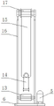
Fig. 1 is main TV structure schematic diagram of the present utility model;
Fig. 2 is left TV structure schematic diagram of the present utility model;
Fig. 3 is right TV structure schematic diagram of the present utility model;
In figure: 1 is the A crown sheave, and 2 is belt, and 3 is polished rod eye, 4 is A tower frame, and 5 is motor, and 6 is base, 7 is the A cylinder, and 8 is the A rolling stand, and 9 is cylinder, 10 is speed reducer for idle-work reversing intelligent oil pumping machine, and 11 are the positioning track, and 12 is the B rolling stand, 13 is the B cylinder, and 14 is polished rod eye, and 15 is belt, 16 is B tower frame, and 17 is the B crown sheave.
The specific embodiment
Below in conjunction with the drawings and specific embodiments, the utility model double tower belt-type self-balancing pumping unit is described in further detail.
As shown in the figure, double tower belt-type self-balancing pumping unit of the present utility model comprises base 6, A tower frame 4, B tower frame 16, A cylinder 7, B cylinder 13, A crown sheave 1, B crown sheave 17, A rolling stand 8, B rolling stand 12, belt 2, polished rod eye 3, motor 5, cylinder 9, speed reducer for idle-work reversing intelligent oil pumping machine 10, positioning track 11.A tower frame 4, B tower frame 16 are assemblied on base 6; Positioning track 11 is fixed on base 6, and A tower frame 4, B tower frame 16 can be crossed along the distance between positioning track 11 slidable adjustment two towers; A rolling stand 8, B rolling stand 12 are separately fixed at the lower end of A tower frame 4, B tower frame 16; A crown sheave 1, B crown sheave 17 are separately positioned on A tower frame 4, B tower frame 16 tower tops; A cylinder 7, B cylinder 13 are assemblied in respectively on A rolling stand 8, B rolling stand 12; Cylinder 9 is to be connected with speed reducer for idle-work reversing intelligent oil pumping machine 10 by belt; Motor 3 is connected with speed reducer for idle-work reversing intelligent oil pumping machine 10; The two ends of belt 2 are polished rod eye 3 and polished rod eye 14 fixedly, strides across A crown sheave 1, A cylinder 7, cylinder 9, B cylinder 13, B crown sheave 17.
During work, motor 5 clockwise rotates, and clockwise rotates through driving cylinder 9 after speed reducer for idle-work reversing intelligent oil pumping machine 10 speed changes, does upstroke by the transmission drive A tower sucker rod of belt 2, and B tower sucker rod is done down stroke; After moving to given stroke, 5 counter-rotatings of electric control system controls motor, thus A tower sucker rod is done down stroke, and B tower sucker rod is done upstroke.In oil pumping process because two sucker rods are connected by belt tension, therefore can balance himself gravity, motor only need provide the merit of lifting oil and the merit of drawing sucker rod need not be provided, and has greatly saved energy.Be arranged on displacement, operating rate and load condition that sensor on polished rod eye can collect sucker rod, and the information that collects is fed back to control system, conduction time and the switching frequency of control system regulating electric machine, thus the purpose of stroke and jig frequency is regulated in realization.
Claims (3)
1. double tower belt-type self-balancing pumping unit, it is characterized in that, comprise: base (6), A tower frame (4), B tower frame (16), A cylinder (7), B cylinder (13), A crown sheave (1), B crown sheave (17), A rolling stand (80), B rolling stand (12), belt (2), polished rod eye (3), motor (5), cylinder (9), speed reducer for idle-work reversing intelligent oil pumping machine (10) and positioning track (11), positioning track (11) is fixed on base (6), A tower frame (4) and B tower frame (16) are fixed on base (6), A tower frame (4) and B tower frame (16) can be crossed along the distance between positioning track (11) slidable adjustment two towers, A rolling stand (8) and B rolling stand (12) are connected in respectively the lower end of A tower frame (4) and B tower frame (16) by turning cylinder, A crown sheave (1) and B crown sheave (17) are connected in A tower frame (4) and B tower frame (16) tower top top by turning cylinder respectively, A cylinder (7) and B cylinder (13) are connected on A rolling stand (8) and B rolling stand (12) by turning cylinder respectively, cylinder (9) is to be connected with speed reducer for idle-work reversing intelligent oil pumping machine (10) by belt, motor (3) is connected with speed reducer for idle-work reversing intelligent oil pumping machine (10), the two ends of belt (2) are polished rod eye (3) and polished rod eye (14) fixedly, strides across successively A crown sheave (1), A cylinder (7), cylinder (9), B cylinder (13) and B crown sheave (17).
2. a kind of double tower belt-type self-balancing pumping unit according to claim 1, is characterized in that: sensor installation on polished rod eye.
3. a kind of double tower belt-type self-balancing pumping unit according to claim 1, is characterized in that: the sliding bearing employing magnetic suspension lubricating system that crown sheave, cylinder are connected with frame.
Priority Applications (1)
| Application Number | Priority Date | Filing Date | Title |
|---|---|---|---|
| CN 201320160203 CN203271683U (en) | 2013-04-02 | 2013-04-02 | Double-tower belt type self-balancing pumping unit |
Applications Claiming Priority (1)
| Application Number | Priority Date | Filing Date | Title |
|---|---|---|---|
| CN 201320160203 CN203271683U (en) | 2013-04-02 | 2013-04-02 | Double-tower belt type self-balancing pumping unit |
Publications (1)
| Publication Number | Publication Date |
|---|---|
| CN203271683U true CN203271683U (en) | 2013-11-06 |
Family
ID=49502121
Family Applications (1)
| Application Number | Title | Priority Date | Filing Date |
|---|---|---|---|
| CN 201320160203 Expired - Fee Related CN203271683U (en) | 2013-04-02 | 2013-04-02 | Double-tower belt type self-balancing pumping unit |
Country Status (1)
| Country | Link |
|---|---|
| CN (1) | CN203271683U (en) |
Cited By (1)
| Publication number | Priority date | Publication date | Assignee | Title |
|---|---|---|---|---|
| CN111075401A (en) * | 2019-12-12 | 2020-04-28 | 中国石油化工股份有限公司 | Gear suspension type parallel double-pump downhole oil production pipe column |
-
2013
- 2013-04-02 CN CN 201320160203 patent/CN203271683U/en not_active Expired - Fee Related
Cited By (2)
| Publication number | Priority date | Publication date | Assignee | Title |
|---|---|---|---|---|
| CN111075401A (en) * | 2019-12-12 | 2020-04-28 | 中国石油化工股份有限公司 | Gear suspension type parallel double-pump downhole oil production pipe column |
| CN111075401B (en) * | 2019-12-12 | 2022-02-18 | 中国石油化工股份有限公司 | Gear suspension type parallel double-pump downhole oil production pipe column |
Similar Documents
| Publication | Publication Date | Title |
|---|---|---|
| CN2931777Y (en) | Intelligent wide belt type pumping unit | |
| CN202152669U (en) | Direct-drive drum full-balanced pumping unit | |
| CN203050645U (en) | Beam-pumping unit | |
| CN101424178B (en) | Crank block type pumping unit | |
| CN213775332U (en) | Energy-saving intelligent beam-pumping unit | |
| CN203271683U (en) | Double-tower belt type self-balancing pumping unit | |
| CN203285395U (en) | Novel vertical long-stroke intelligent oil pumping unit | |
| CN103924949A (en) | Direct-drive ball screw transmission oil pumping unit | |
| CN106894790A (en) | A kind of link balance beam pumping unit | |
| CN100564794C (en) | Lever balance head sheave long stroke pumping unit | |
| CN201232539Y (en) | Wheel shaft pumping unit | |
| CN202673256U (en) | Cluster well one-machine double-production lifting device | |
| CN104763384A (en) | Oscillating bar tower type intelligent oil pumping unit | |
| CN105197639A (en) | Slitter edge winding machine for bag making machine | |
| CN202325429U (en) | Long-stroke dual-well oil pumping unit | |
| CN201771474U (en) | Self-balancing double-well oil pumping unit | |
| CN202100241U (en) | Slide block type positive torsion oil pumping unit | |
| CN205297491U (en) | Novel screw beam -pumping unit | |
| CN202955196U (en) | Chain transmission reversing device of beam-pumping unit | |
| CN203427032U (en) | Conveying mechanical hand | |
| CN206681714U (en) | A kind of link balance beam pumping unit | |
| CN203188980U (en) | Self-balancing type digital oil pumping machine | |
| CN201460835U (en) | Wheel axle weight type double-rod hydraulic pumping unit | |
| CN201934074U (en) | Heavy-hammer beamless type strong-efficiency energy-saving pumping unit | |
| CN201043456Y (en) | Lever-balancing crown sheave type long stroke well pumping unit |
Legal Events
| Date | Code | Title | Description |
|---|---|---|---|
| C14 | Grant of patent or utility model | ||
| GR01 | Patent grant | ||
| C17 | Cessation of patent right | ||
| CF01 | Termination of patent right due to non-payment of annual fee |
Granted publication date: 20131106 Termination date: 20140402 |