CN203235395U - Flue gas desulfurization equipment - Google Patents
Flue gas desulfurization equipment Download PDFInfo
- Publication number
- CN203235395U CN203235395U CN 201320169756 CN201320169756U CN203235395U CN 203235395 U CN203235395 U CN 203235395U CN 201320169756 CN201320169756 CN 201320169756 CN 201320169756 U CN201320169756 U CN 201320169756U CN 203235395 U CN203235395 U CN 203235395U
- Authority
- CN
- China
- Prior art keywords
- flue gas
- slurry
- circulating pump
- cylindrical shell
- demister
- Prior art date
- Legal status (The legal status is an assumption and is not a legal conclusion. Google has not performed a legal analysis and makes no representation as to the accuracy of the status listed.)
- Expired - Fee Related
Links
Images
Landscapes
- Treating Waste Gases (AREA)
Abstract
The utility model discloses flue gas desulfurization equipment which is equipment for removing sulfur dioxide and dusts in flue gas. The flue gas desulfurization equipment comprises a cylindrical shell, wherein an exhaust hole is formed in the top part of the shell, a slag discharge hole is formed in the bottom of the shell, a demister is installed at the upper part in the cylindrical shell, a spray thrower used for spraying slurry is installed below the demister, a hydrocyclone is arranged at the middle part of the demister, an absorption liquid collector is arranged at the lower part of the demister, a slurry circulating pump is arranged outsides the cylindrical shell, the inlet of the slurry circulating pump is connected with the absorption liquid collector, and the outlet of the slurry circulating pump is connected with the hydrocyclone by virtue of a circulating slurry pipeline and a flue gas inlet pipeline. With the adoption of the flue gas desulfurization equipment, the flue gas tangentially enters the hydrocyclone in a segmented way, and the segmented flue gas and absorption liquid which is shunted by the absorption liquid collector at the bottom pass through the slurry circulating pump, are mixed with flue gas from the inlet of the slurry circulating pump and then enter the shell again; after the mixture is strengthened and absorbed by the hydrocyclone, a solid material flows downwards from an outer ring of the hydrocyclone, gas flows upwards and enters a spraying absorption section, secondary spraying and washing are carried out on the gas by virtue of the absorption slurry which is sprayed by a slurry distributer, and the desulfurization efficiency is improved.
Description
Technical field
The utility model relates to a kind of flue gas desulfurization device, more specifically says a kind of sulfur dioxide in flue gas and dust separation equipment out, can be used for the coal-burned industrial boiler of power plant, cement plant and other relevant industries and the flue gas desulfurization and dedusting of kiln.
Background technology
Coal is the main body energy in China, coal account for that total energy consumes more than 70%, and the SO that is produced by fire coal
2Account for national SO
290% of total release.Therefore, fire coal boiler fume is carried out desulfurization, control SO
2Discharging be an urgent demand of sustainable development, realize that the purpose efficient, clean utilization of coal is the important topic that current China faces.
Flue gas desulfurization be exactly with physics or the chemistry method with the SO in the flue gas
2Fixed and removed.Flue gas desulfurization can be divided into dry method, semidry method and wet method three classes by desulfurization method.Dry desulfurization refers to adopt powdery or granular desulfuration agent to remove SO in the flue gas
2Semidry method refers to desulfurizing agent desulfurization under dry state, regenerates under hygrometric state, perhaps desulfurization under hygrometric state, processes the desulfurization of desulfurization product under dry state; Wet method refers to adopt slurries shape desulfurizing agent to remove SO in the flue gas
2Wet desulphurization efficient, technology maturation, but investment and operating cost are high; Semi-dry desulphurization efficient is medium, and investment and operating cost are low than wet method, and comprehensive economy is better; Dry desulfurizing process is simple, and investment and operating cost are low, and little without fouling, corrosion, but desulfuration efficiency is lower.
Wet process of FGD equipment has desulfurizing tower and desulfurizing dust-collector.As between desulphurization plant General Requirements gas-liquid larger contact area being arranged, disturbance is strong between gas-liquid, the absorption resistance is little, stable operation, and simple in structure, non-scaling does not stop up.Desulfurizing tower is divided into again spray column, packed tower, spray tower, plate column, venturi absorption tower and desulfurization dust removing integral equipment etc.
Conventional desulphurization plant or exist between gas-liquid a little less than the turbulence level absorbs resistance large, or form carry secretly, back-mixing causes gas, bad contact environment or the problems such as easily fouling, obstruction between liquid.At present, coal production amount and the consumption figure of China are continuing to increase on the one hand, and coal is made a low multiple use, and environmental pollution is serious; On the other hand, more and more stricter to the restriction of pollutant emission along with country improves the requirement of environmental quality, the desulphurization plant of general type is used and also is restricted.
Summary of the invention
The purpose of this utility model is between, gas-liquid single for present desulphurization plant desulfurization method a little less than the turbulence level, absorbs the problems such as resistance is large, causes the poor weak point of assimilation effect, and a kind of compact conformation is provided, small investment, floor space is little, good absorbing effect, the flue gas desulfurization device that desulfuration efficiency is high.
The utility model is achieved by the following technical solution: a kind of flue gas desulfurization device, comprise cylindrical shell, and the top of cylindrical shell is provided with exhaust outlet, and the bottom is provided with slag-drip opening; Top in cylindrical shell is equiped with demister, be equiped with the spray thrower for sprayed slurry below the demister, the middle part is furnished with cyclone, the bottom is provided with the absorption liquid collector, cylindrical shell has slurry circulating pump outward, described slurry circulating pump import is connected with the absorption liquid collector through pipeline, and outlet is connected with cyclone with the gas approach pipeline by the loop slurry pipeline.
Cyclone in the described cylindrical shell is arranged two-layer at least, is up and down to distribute.
Described absorption liquid collector is back taper.
The structure of above-mentioned whole equipment has formed the spray-absorption section, eddy flow is strengthened absorber portion and slurries circulation section; The flue gas segmentation tangentially enters cyclone, the sprayed slurry that distributes with column bottom absorption liquid collector enters in the cylindrical shell after slurry circulating pump mixes with the import flue gas again, after cyclone is strengthened absorption, solid materials etc. flow downward from the outer ring of cyclone, gas upwards flows into the spray-absorption section, the absorption slurries that spray out via the slurries spray thrower are through again spray washing effect, thereby have strengthened desulfurized effect.
The beneficial effects of the utility model are: desulfuration efficiency is high, spray-absorption and eddy flow reinforcement absorption are combined, especially flue gas has carried out the mixing of high turbulence level with the absorption slurries of circulation entering cyclone, in high turbulence level centrifugal force field, strengthened mass transport process after entering cyclone, improved assimilation effect, had conventional spray-absorption and eddy flow and strengthen the double effects that absorbs; This equipment desulfuration efficiency is high, and disengaging time is short, and treating capacity is large.Have dedusting and desulphurization integrated, compact equipment, floor space is little, reduces investment outlay, the on-the-spot characteristics such as easy for installation.
Description of drawings
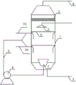
Accompanying drawing is structural representation of the present utility model.
Among the figure: 1, cylindrical shell, 2, demister, 3, spray thrower, 4, exhaust outlet, 5, slag-drip opening, 6, cyclone, 7, the absorption liquid collector, 8, slurry circulating pump, 9, the loop slurry pipeline, 10, the gas approach pipeline.
The specific embodiment
The utility model will be further described below in conjunction with accompanying drawing and an embodiment.
As shown in Figure 1, comprise cylindrical shell 1, the top of cylindrical shell 1 is provided with exhaust outlet 4, and the bottom is provided with slag-drip opening 5; Top in cylindrical shell 1 is equiped with demister 2, be equiped with the spray thrower 3 for sprayed slurry below the demister 2, the middle part is furnished with cyclone 6, the bottom is provided with absorption liquid collector 7, slurry circulating pump 8 is arranged outside the cylindrical shell 1, described slurry circulating pump 8 imports are connected with absorption liquid collector 7 through pipeline, and outlet is connected with the gas approach pipeline and is connected with cyclone 6 by loop slurry pipeline 9.Cyclone 6 in the present embodiment cylindrical shell 1 is arranged two-layer, is up and down to distribute.Gas approach pipeline 10 is connected with the loop slurry pipeline and is connected with cyclone 6 after connecting again.Be the convenient absorption liquid of collecting, absorption liquid collector E is back taper.
Pending flue gas enter gas approach pipeline 10 again with mix with the slurries in the loop slurry pipeline 9 after, tangentially enter cyclone 6, under the eddy flow force field, slurries absorb the SO in the flue gas
2, and SO has been strengthened in the eddy flow field of force of high turbulence level
2Absorption.The gas that proportion is little in the gas-liquid mixed material after eddy flow section absorption inwardly, upwards flow, heavy solid, liquid material outwards, flow downward.The gas that upwards flows enters the spray-absorption section, and the fresh absorption slurries that replenish from spray thrower 3 flow downward, and the two countercurrent movement produces absorption, has further been absorbed SO
2Gas continue to move upward, form purified gas through after demister 2 demists, discharge from the top vent 4 of cylindrical shell 1.The solid, liquid that the spray-absorption section flows downward enters the eddy flow absorber portion, further absorbs to enter SO in the fresh smoke
2The solid, liquid material that flows downward in the cyclone enters the slurries circulation section, the absorption liquid that absorbs that partly do not reach capacity enters absorption liquid collector 7, form loop slurry, after slurry circulating pump 8 extraction pressurizations are by pipeline and fresh smoke mixing, tangentially enter cyclone 6 and carry out Absorption Desulfurization.The solid acid sludge that forms and the slurries that absorb that reach capacity are discharged through slag-drip opening 5, thereby have reached the purpose of spraying foam post desulfurization and dedusting.
Claims (3)
1. flue gas desulfurization device, it is characterized in that: comprise cylindrical shell (1), the top of cylindrical shell (1) is provided with exhaust outlet (4), and the bottom is provided with slag-drip opening (5); Top in cylindrical shell (1) is equiped with demister (2), be equiped with the spray thrower (3) for sprayed slurry below the demister (2), the middle part is furnished with cyclone (6), the bottom is provided with absorption liquid collector (7), slurry circulating pump (8) is arranged outside the cylindrical shell (1), described slurry circulating pump (8) import is connected with absorption liquid collector (7) through pipeline, and outlet is connected 10 by loop slurry pipeline (9) with the gas approach pipeline) be connected with cyclone (6).
2. a kind of flue gas desulfurization device according to claim 1, it is characterized in that: the cyclone (6) in the described cylindrical shell (1) is arranged two-layer at least, is up and down to distribute.
3. a kind of flue gas desulfurization device according to claim 1, it is characterized in that: described absorption liquid collector (7) is back taper.
Priority Applications (1)
| Application Number | Priority Date | Filing Date | Title |
|---|---|---|---|
| CN 201320169756 CN203235395U (en) | 2013-04-07 | 2013-04-07 | Flue gas desulfurization equipment |
Applications Claiming Priority (1)
| Application Number | Priority Date | Filing Date | Title |
|---|---|---|---|
| CN 201320169756 CN203235395U (en) | 2013-04-07 | 2013-04-07 | Flue gas desulfurization equipment |
Publications (1)
| Publication Number | Publication Date |
|---|---|
| CN203235395U true CN203235395U (en) | 2013-10-16 |
Family
ID=49312732
Family Applications (1)
| Application Number | Title | Priority Date | Filing Date |
|---|---|---|---|
| CN 201320169756 Expired - Fee Related CN203235395U (en) | 2013-04-07 | 2013-04-07 | Flue gas desulfurization equipment |
Country Status (1)
| Country | Link |
|---|---|
| CN (1) | CN203235395U (en) |
Cited By (5)
| Publication number | Priority date | Publication date | Assignee | Title |
|---|---|---|---|---|
| CN103736381A (en) * | 2013-12-24 | 2014-04-23 | 航天环境工程有限公司 | Dust removal device and dust removal method for sintering flue gas by shunted and graded desulfurization |
| CN106659970A (en) * | 2015-03-16 | 2017-05-10 | 富士电机株式会社 | Exhaust gas treatment apparatus |
| CN110141957A (en) * | 2019-06-19 | 2019-08-20 | 众一阿美科福斯特惠勒工程有限公司 | A kind of device and method of spray fluidisation separation nitrogen oxides |
| CN111282399A (en) * | 2020-03-02 | 2020-06-16 | 上海济德能源环保技术有限公司 | Medium-high temperature gas purification cooler |
| CN112827338A (en) * | 2020-12-30 | 2021-05-25 | 安徽泽升科技有限公司 | Green and environment-friendly laboratory waste gas treatment method and device |
-
2013
- 2013-04-07 CN CN 201320169756 patent/CN203235395U/en not_active Expired - Fee Related
Cited By (6)
| Publication number | Priority date | Publication date | Assignee | Title |
|---|---|---|---|---|
| CN103736381A (en) * | 2013-12-24 | 2014-04-23 | 航天环境工程有限公司 | Dust removal device and dust removal method for sintering flue gas by shunted and graded desulfurization |
| CN106659970A (en) * | 2015-03-16 | 2017-05-10 | 富士电机株式会社 | Exhaust gas treatment apparatus |
| CN106659970B (en) * | 2015-03-16 | 2018-05-08 | 富士电机株式会社 | Emission-control equipment |
| CN110141957A (en) * | 2019-06-19 | 2019-08-20 | 众一阿美科福斯特惠勒工程有限公司 | A kind of device and method of spray fluidisation separation nitrogen oxides |
| CN111282399A (en) * | 2020-03-02 | 2020-06-16 | 上海济德能源环保技术有限公司 | Medium-high temperature gas purification cooler |
| CN112827338A (en) * | 2020-12-30 | 2021-05-25 | 安徽泽升科技有限公司 | Green and environment-friendly laboratory waste gas treatment method and device |
Similar Documents
| Publication | Publication Date | Title |
|---|---|---|
| CN102228788B (en) | Device and method for removing sulfur dioxide and dioxin from sintering flue gas | |
| CN101422691B (en) | Multi-pollutant removing technique and device of fuel coal smoke | |
| CN100496676C (en) | Wet ammonia flue gas cleaning technology simultaneously removing various pollutant and system thereof | |
| CN203235395U (en) | Flue gas desulfurization equipment | |
| CN101259364A (en) | Wet desulphurization technique for sintered flue gas | |
| CN201543380U (en) | Efficient wet-type flue gas desulfurization device employing dual-alkali method for industrial coal-fired boiler | |
| CN202070280U (en) | Boiler waste gas swirl plate tower | |
| CN201840979U (en) | Smoke gas comprehensive treatment system | |
| CN101007238A (en) | Radial grading desulfurization dust-removing device | |
| CN104399367A (en) | Smoke washing device with scaling-shaped hole plate | |
| CN201168563Y (en) | Pneumatic flow guide dust removing and desulferizing device | |
| CN102836631A (en) | Method and device for selectively removing hydrogen sulfide from gas by utilizing amine droplets | |
| CN202173882U (en) | Device for removing sulfur dioxide and dioxin in sintering flue gas | |
| CN201949809U (en) | Multifunctional dynamic wave comprehensive washer | |
| CN201735331U (en) | Waste gas desulfurization device | |
| CN203002194U (en) | Turbulent ball turbocharged composite desulphurization dedusting tower | |
| CN201482400U (en) | Tray type pneumatic emulsification desulfurizing tower | |
| CN203899442U (en) | Efficient desulfurizing, dedusting and demisting device adopting multi-stage reducing and multi-stage spraying | |
| CN201389423Y (en) | Flue gas desulphurization dust removing tower for coal burning boiler | |
| CN108854499A (en) | A kind of furfural dregs boiler smoke magnesia FGD purification device | |
| CN202478814U (en) | Integral equipment integrating downstream washing desulfuration with ozone jetting back-flow denitration | |
| CN2376992Y (en) | Turbulent flue gas purifying tower | |
| CN204320092U (en) | A kind of flue gas washing mechanism with convergent-divergent shape orifice plate | |
| CN104437039B (en) | Denitration demister after wet desulphurization and method | |
| CN204447724U (en) | A kind of Pneumatic emulsifying device of dedusting and desulfurizing tower |
Legal Events
| Date | Code | Title | Description |
|---|---|---|---|
| C14 | Grant of patent or utility model | ||
| GR01 | Patent grant | ||
| C17 | Cessation of patent right | ||
| CF01 | Termination of patent right due to non-payment of annual fee |
Granted publication date: 20131016 Termination date: 20140407 |