CN203136590U - Folium mori cutting machine - Google Patents
Folium mori cutting machine Download PDFInfo
- Publication number
- CN203136590U CN203136590U CN 201220727783 CN201220727783U CN203136590U CN 203136590 U CN203136590 U CN 203136590U CN 201220727783 CN201220727783 CN 201220727783 CN 201220727783 U CN201220727783 U CN 201220727783U CN 203136590 U CN203136590 U CN 203136590U
- Authority
- CN
- China
- Prior art keywords
- drum shaft
- countershaft
- blade
- auxiliary
- leaf chopping
- Prior art date
- Legal status (The legal status is an assumption and is not a legal conclusion. Google has not performed a legal analysis and makes no representation as to the accuracy of the status listed.)
- Expired - Fee Related
Links
Images


Abstract
The utility model relates to a folium mori cutting machine. The folium mori cutting machine comprises a machine frame, a feed port, a discharge port, a driving device and a cutting device, wherein the machine frame is a cuboid cavity, and the upper end of the machine frame is connected with the feed port; the cutting device is mounted below the feed port; the discharge port is formed in the lower part of the cutting device; and the driving device is arranged at the bottom of the machine frame. The innovation points lie in that the cutting device comprises a blade group and a drum shaft which cooperate with each other; the blade group is connected to an auxiliary shaft through the screw threads at the two ends of the auxiliary shaft; radial groove veins are arranged on the drum shaft, and auxiliary blades are welded on the drum shaft, an electric motor in the driving device is used for driving the drum shaft to rotate through a belt, and the drum shaft is in transmission connection with the auxiliary shaft through chain wheels; the blade group on the auxiliary shaft comprises circular blades and semicircular blades which are in a staggered arrangement, the diameter of the auxiliary shaft is equal to that of the drum shaft; and an auxiliary blade carrier is arranged on the auxiliary shaft and is fixed at the top end of the machine frame through a bolt. The folium mori cutting machine can efficiently cut a folium mori into folium-mori pieces with different sizes and guarantees the food of silkworms of all ages.
Description
Technical field
The utility model relates to agricultural mechanical field, particularly a kind of leaf chopping machine that can cut mulberry leaf.
Background technology
Along with the continuous development of modern agriculture, people are also more and more higher to the requirement of silk cocoon, and are also increasing to the demand of silk cocoon, particularly when feeding the young silkworm in 1-3 age, and the fritter that the mulberry leaf of bulk must be shredded.Generally all be to be cut by artificial cutter in the past, also invented out also a little chopped leaves of mulberry equipment in recent years in the industry in succession.
Present leaf chopping machine is made up of frame, charging aperture, discharging opening, drive unit, cutter sweep; it can only excise the mulberry leaf with a kind of size; its mulberry leaf can only satisfy a kind of usefulness of nibbling of age bracket, and the silkworm of other all ages and classes then can not eat, so present leaf chopping machine needs to improve.
Summary of the invention
The technical problems to be solved in the utility model provides a kind of leaf chopping machine that can cut out mulberry leaf multiple size.
For solving the problems of the technologies described above, the technical solution of the utility model is: a kind of leaf chopping machine, comprise frame, charging aperture, discharging opening, drive unit, cutter sweep, described frame is the cuboid cavity, the upper end connects charging aperture, described charging aperture bottom is equipped with cutter sweep, described discharging opening is positioned at the cutter sweep bottom, described drive unit is located at the frame bottom, its innovative point is: described cutter sweep comprises set of blades and the drum shaft that cooperatively interacts, on the countershaft that is threaded in of set of blades by the axle two ends; Have the radial slot line on the described drum shaft and be welded with auxiliary blade, by the belt driven rotary, drum shaft is connected by chain gear transmission with countershaft drum shaft by the electromotor in the drive unit; Set of blades on the described countershaft is that circular knife and semicircle blade sheet are spaced and form, and the countershaft diameter is equivalent to the drum shaft diameter; There is auxiliary tool head described countershaft top, and described auxiliary tool head adopts and is bolted to the frame top.
Further, the transmission direction of described drum shaft and countershaft is consistent.
Further, the sprocket diameter on described countershaft and the drum shaft is than being 2:1.
Further, the gearratio of described countershaft and drum shaft is 2:1.
Further, the groove line is n on the described cylinder, n 〉=1, and equidistant axial distribution.Be welded with some auxiliary blade at the interval of groove line, and axially-aligned is on drum shaft.
Further, described auxiliary blade is that rectangle and end mill have cutting edge.
Further, on the circular knife on the described countershaft and its circumference of semicircle blade all mill cutting edge arranged.
Further, leave the gap between the set of knives on the described countershaft and the auxiliary blade on the drum shaft, the gap is for that fix or adjustable.
Further, described auxiliary tool head comprises:
Two supports, described support are rectangle iron plate, have through hole on its plate body;
One cross bar, described cross bar are the trigone structure of cuboid iron plate center bending;
One blade, described blade are the cuboid thin slice;
Two striker plates, described striker plate for the countershaft semicircle thin slice that assembly closes of fixing a cutting tool;
One spacer grid, described spacer grid is rearranged by several iron wire equidistant intervals;
Described cross bar two ends all are welded with support, and cross bar one face down bonding is connected to spacer grid, and the cross bar bottom is welded with blade, and two ends of blade are welded with striker plate.
Further, the iron wire in the spacer grid on the described auxiliary tool head inserts in the gap of countershaft blade.
Advantage of the present utility model is: it is that circular knife and semicircle blade sheet are spaced design and can make the mulberry leaf that cut out be the unequal fritter of size that the utility model adopts blade on the countershaft, is fit to eating of an age bracket silkworm; And the design of auxiliary tool head has guaranteed that the mulberry leaf piece does not produce one from countershaft and breaks away out, and fritters the mulberry leaf piece.
Description of drawings
Fig. 1 is the utility model example structure schematic diagram.
Fig. 2 is the utility model auxiliary tool head structural representation.
Fig. 3 is the utility model cutter sweep cross section structure schematic diagram.
Fig. 4 is the set of knives cross section structure schematic diagram on the utility model countershaft.
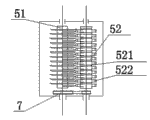
Among the figure: 1 frame, 2 charging apertures, 3 discharging openings, 4 drive units, 41 electromotor, 42 belts, 5 cutter sweeps, 51 countershafts, 511 circular knifes, 512 semicircle blades, 52 drum shafts, 521 groove lines, 522 auxiliary blade, 6 auxiliary tool heads, 61 supports, 62 cross bars, 63 blades, 64 striker plates, 65 spacer grid, 7 sprocket wheels.
Embodiment
As shown in Figure 1, the utility model is made of frame 1, charging aperture 2, discharging opening 3, drive unit 4, cutter sweep 5, auxiliary cutter 6.Its mid frame 1 is the cuboid cavity, and charging aperture 2 is for lacking the inverted pyramid funnel shaped on top, and discharging opening 3 is downward-sloping in frame 1 to be gone out outside the frame, and drive unit 4 comprises electromotor 41 and belt 42.Frame 1 upper end connects charging aperture 2, charging aperture 2 bottoms are equipped with cutter sweep 5, and discharging opening 3 is positioned at cutter sweep 5 bottoms, and drive unit 4 adopts bolt in frame 1 bottom, belt 42 in the drive unit 4 is installed on electromotor 41 output shafts, and the other end is installed in the cutter sweep 5.
As shown in Figure 2, auxiliary tool head 6 comprises: support 61, cross bar 62, blade 63, striker plate 64, spacer grid 65, and described support 61 is rectangle iron plate, has through hole on its plate body; Described cross bar 62 is the trigone structure of cuboid iron plate center bending; Described blade 63 is the cuboid thin slice; Described striker plate 64 for the countershaft 51 semicircle thin slice that assembly closes of fixing a cutting tool; Described spacer grid 65 is rearranged by several iron wire equidistant intervals; Described cross bar 62 two ends all are welded with support 61, and cross bar 62 1 face down bondings are connected to spacer grid 65, and cross bar 62 bottoms are welded with blade 63, and 63 two ends of blade are welded with striker plate 64.
Described in conjunction with Fig. 1 and Fig. 2, auxiliary tool head 6 adopts the top that is bolted to frame 1 by the support 6.1 on it.
As shown in Figure 3, present embodiment cutter sweep cross section structure schematic diagram leaves the gap between the auxiliary blade 522 on the set of blades on the countershaft 51 and the drum shaft 52.Figure middle sprocket 7 is fixed on countershaft 51 and the drum shaft 52 by the axle head thread helix, and at sprocket wheel 7 belt is installed.
Described in conjunction with Fig. 1 and Fig. 3, belt 42 other ends of drive unit 4 are installed on the drum shaft 52.When the work operation, motor changes 41 and moves, and drives drum shaft 52 and rotates, and the sprocket wheel on the drum shaft 52 makes countershaft 51 realize rotating in the same way by belt.
With lathe turning several groove lines 521 are arranged on the drum shaft 52, between adjacent slot line 521, be welded with auxiliary blade 522 and auxiliary blade 522 and drum shaft 52 angled fixing.
Set of blades on the countershaft 51 is spaced by circular knife 511 and semicircle blade sheet 512 and forms.All grind on its circumference cutting edge is arranged.
Operation principle: when leaf chopping machine in when work; drive rotation by the motor drives drum shaft; drum shaft is in transmission connection by chain and makes the set of knives on countershaft and the axle thereof rotate; mulberry leaf are put into from charging aperture; again by on the set of knives on the countershaft in the cutter sweep and the cylinder during gap between the auxiliary blade; set of knives is cut it; the meeting that mulberry leaf piece after the cutting has is up just in time run into spacer grid on the auxiliary tool head and it is stopped and is carried out secondary cut under the rotation of axle drives; striker plate on the auxiliary tool head is positioned on the bearing external member of countershaft and frame, can stop the landing from here of mulberry leaf piece.The mulberry leaf piece that has cut on set of knives and the cylinder between the auxiliary blade landing to discharging opening.The utility model is easy to use, saves a large amount of manpowers.
Claims (10)
1. leaf chopping machine, comprise frame (1), charging aperture (2), discharging opening (3), drive unit (4), cutter sweep (5), described frame (1) is the cuboid cavity, the upper end connects charging aperture (2), described charging aperture (2) bottom is equipped with cutter sweep (5), described discharging opening (3) is positioned at cutter sweep (5) bottom, described drive unit (4) is located at frame (1) bottom, it is characterized in that: described cutter sweep (5) comprises set of blades and the drum shaft (52) that cooperatively interacts, on the countershaft that is threaded in (51) of set of blades by the axle two ends; Have radial slot line (521) on the described drum shaft (52) and be welded with auxiliary blade (522), by belt (42) driven rotary, drum shaft (52) and countershaft (51) are in transmission connection by sprocket wheel (7) drum shaft (52) by the electromotor (41) in the drive unit (4); To be circular knife (511) with semicircle blade (512) sheet be spaced set of blades on the described countershaft (51) forms, and countershaft (51) diameter is equivalent to drum shaft (52) diameter; There is auxiliary tool head (6) described countershaft (51) top, and described auxiliary tool head (6) adopts and is bolted to frame (1) top.
2. a kind of leaf chopping machine according to claim 1, it is characterized in that: described drum shaft (52) is consistent with countershaft (51) transmission direction.
3. a kind of leaf chopping machine according to claim 1 and 2 is characterized in that: the sprocket wheel on described countershaft and the drum shaft (7) diameter is than being 2:1.
4. a kind of leaf chopping machine according to claim 1 and 2 is characterized in that: described countershaft (51) is 2:1 with the gearratio of drum shaft (52).
5. a kind of leaf chopping machine according to claim 1 is characterized in that: it be n that described cylinder (52) is gone up groove line (521), n 〉=1, and equidistant axial distribution; Be welded with some auxiliary blade (522) at the interval of groove line (521), and axially-aligned is on drum shaft (52).
6. a kind of leaf chopping machine according to claim 1 or 5 is characterized in that: described auxiliary blade (522) has cutting edge for rectangle and end mill.
7. according to claim 1 or 5 or 6 described a kind of leaf chopping machines, it is characterized in that: all grinding on the circular knife on the described countershaft (511) and its circumference of semicircle blade (512) has cutting edge.
8. a kind of leaf chopping machine according to claim 1 is characterized in that: leave the gap between the auxiliary blade (522) on the set of knives on the described countershaft (51) and the drum shaft (52), the gap is for fixing or adjustable.
9. a kind of leaf chopping machine according to claim 1, it is characterized in that: described auxiliary tool head (6) comprising:
Two supports (61), described support (61) is rectangle iron plate, has through hole on its plate body;
One cross bar (62), described cross bar (62) are the trigone structure of cuboid iron plate center bending;
One blade (63), described blade (63) is the cuboid thin slice;
Two striker plates (64), described striker plate (64) for countershaft (51) the semicircle thin slice that assembly closes of fixing a cutting tool;
One spacer grid (65), described spacer grid (65) is rearranged by several iron wire equidistant intervals;
Described cross bar (62) two ends all are welded with support (61), and cross bar (62) one face down bondings are connected to spacer grid (65), and cross bar (62) bottom is welded with blade, and two ends of blade are welded with striker plate (64).
10. according to claim 1 or 9 described a kind of leaf chopping machines, it is characterized in that: the iron wire in the spacer grid (65) on the described auxiliary tool head (6) inserts in the gap of countershaft (51) blade.
Priority Applications (1)
| Application Number | Priority Date | Filing Date | Title |
|---|---|---|---|
| CN 201220727783 CN203136590U (en) | 2012-12-26 | 2012-12-26 | Folium mori cutting machine |
Applications Claiming Priority (1)
| Application Number | Priority Date | Filing Date | Title |
|---|---|---|---|
| CN 201220727783 CN203136590U (en) | 2012-12-26 | 2012-12-26 | Folium mori cutting machine |
Publications (1)
| Publication Number | Publication Date |
|---|---|
| CN203136590U true CN203136590U (en) | 2013-08-21 |
Family
ID=48964166
Family Applications (1)
| Application Number | Title | Priority Date | Filing Date |
|---|---|---|---|
| CN 201220727783 Expired - Fee Related CN203136590U (en) | 2012-12-26 | 2012-12-26 | Folium mori cutting machine |
Country Status (1)
| Country | Link |
|---|---|
| CN (1) | CN203136590U (en) |
Cited By (4)
| Publication number | Priority date | Publication date | Assignee | Title |
|---|---|---|---|---|
| CN104996107A (en) * | 2015-07-31 | 2015-10-28 | 李胜斌 | Mulberry leaf cutter |
| CN106034581A (en) * | 2016-07-22 | 2016-10-26 | 朱庆延 | Plant branch and leaf separation device |
| CN106925392A (en) * | 2015-12-31 | 2017-07-07 | 韦华江 | Mulberry leaf four directions cutting machine |
| CN113228964A (en) * | 2021-05-31 | 2021-08-10 | 周元铎 | Mulberry leaf and mulberry branch cutting machine |
-
2012
- 2012-12-26 CN CN 201220727783 patent/CN203136590U/en not_active Expired - Fee Related
Cited By (5)
| Publication number | Priority date | Publication date | Assignee | Title |
|---|---|---|---|---|
| CN104996107A (en) * | 2015-07-31 | 2015-10-28 | 李胜斌 | Mulberry leaf cutter |
| CN106925392A (en) * | 2015-12-31 | 2017-07-07 | 韦华江 | Mulberry leaf four directions cutting machine |
| CN106034581A (en) * | 2016-07-22 | 2016-10-26 | 朱庆延 | Plant branch and leaf separation device |
| CN106034581B (en) * | 2016-07-22 | 2023-08-08 | 朱庆延 | Plant branch and leaf splitter |
| CN113228964A (en) * | 2021-05-31 | 2021-08-10 | 周元铎 | Mulberry leaf and mulberry branch cutting machine |
Similar Documents
| Publication | Publication Date | Title |
|---|---|---|
| CN105211781B (en) | A kind of four knives circle basin type chopped hot pepper machine | |
| CN104782331A (en) | Heterodromous double-roller anti-twining banana straw smashing and returning machine | |
| CN203136590U (en) | Folium mori cutting machine | |
| CN201192650Y (en) | Branches disintegrator | |
| CN201657641U (en) | Spiral straw crushing device | |
| CN202146809U (en) | Machine for kneading straws into filaments | |
| CN202028446U (en) | Crusher for hard materials | |
| CN102152328B (en) | Rotary slicing machine | |
| CN201409326Y (en) | Mulberry leaf shredding machine | |
| CN204948841U (en) | Combination machine is surely rubbed to special straw hand hay cutter of industrialized agriculture | |
| CN203470106U (en) | Novel crushing, rubbing and yarn-splitting machine with movable cutter head | |
| CN2875077Y (en) | Bone cutting machine | |
| CN205848064U (en) | A kind of pulverizing unit | |
| CN211729850U (en) | Shredder blade | |
| CN201579827U (en) | High-efficiency ginger slicing equipment | |
| CN211134194U (en) | Raw material crusher of root of kudzu vine powder processing usefulness | |
| CN208356967U (en) | Serrated knife formula vegetables crusher | |
| CN211709438U (en) | Mulberry leaf shredding device | |
| CN201733642U (en) | Mulberry chopping machine | |
| CN203316216U (en) | Crusher of sugarcane leaves | |
| CN201931485U (en) | Rotary slicing machine | |
| CN106387927A (en) | Hawthorn fruit kernel removing and slicing all-in-one machine | |
| CN201986658U (en) | Lentinus edodes slicer | |
| CN102240583B (en) | High-speed biomass crusher and crushing method thereof | |
| CN204471448U (en) | A kind of medicine cutter |
Legal Events
| Date | Code | Title | Description |
|---|---|---|---|
| C14 | Grant of patent or utility model | ||
| GR01 | Patent grant | ||
| C17 | Cessation of patent right | ||
| CF01 | Termination of patent right due to non-payment of annual fee |
Granted publication date: 20130821 Termination date: 20131226 |