CN203115583U - Lamp, lamp device and lighting fixture - Google Patents
Lamp, lamp device and lighting fixture Download PDFInfo
- Publication number
- CN203115583U CN203115583U CN2013200463377U CN201320046337U CN203115583U CN 203115583 U CN203115583 U CN 203115583U CN 2013200463377 U CN2013200463377 U CN 2013200463377U CN 201320046337 U CN201320046337 U CN 201320046337U CN 203115583 U CN203115583 U CN 203115583U
- Authority
- CN
- China
- Prior art keywords
- lamp
- radiator
- light source
- resettlement section
- outer cover
- Prior art date
- Legal status (The legal status is an assumption and is not a legal conclusion. Google has not performed a legal analysis and makes no representation as to the accuracy of the status listed.)
- Expired - Lifetime
Links
Images


Classifications
-
- F—MECHANICAL ENGINEERING; LIGHTING; HEATING; WEAPONS; BLASTING
- F21—LIGHTING
- F21V—FUNCTIONAL FEATURES OR DETAILS OF LIGHTING DEVICES OR SYSTEMS THEREOF; STRUCTURAL COMBINATIONS OF LIGHTING DEVICES WITH OTHER ARTICLES, NOT OTHERWISE PROVIDED FOR
- F21V23/00—Arrangement of electric circuit elements in or on lighting devices
- F21V23/001—Arrangement of electric circuit elements in or on lighting devices the elements being electrical wires or cables
- F21V23/002—Arrangements of cables or conductors inside a lighting device, e.g. means for guiding along parts of the housing or in a pivoting arm
-
- F—MECHANICAL ENGINEERING; LIGHTING; HEATING; WEAPONS; BLASTING
- F21—LIGHTING
- F21K—NON-ELECTRIC LIGHT SOURCES USING LUMINESCENCE; LIGHT SOURCES USING ELECTROCHEMILUMINESCENCE; LIGHT SOURCES USING CHARGES OF COMBUSTIBLE MATERIAL; LIGHT SOURCES USING SEMICONDUCTOR DEVICES AS LIGHT-GENERATING ELEMENTS; LIGHT SOURCES NOT OTHERWISE PROVIDED FOR
- F21K9/00—Light sources using semiconductor devices as light-generating elements, e.g. using light-emitting diodes [LED] or lasers
- F21K9/20—Light sources comprising attachment means
-
- F—MECHANICAL ENGINEERING; LIGHTING; HEATING; WEAPONS; BLASTING
- F21—LIGHTING
- F21V—FUNCTIONAL FEATURES OR DETAILS OF LIGHTING DEVICES OR SYSTEMS THEREOF; STRUCTURAL COMBINATIONS OF LIGHTING DEVICES WITH OTHER ARTICLES, NOT OTHERWISE PROVIDED FOR
- F21V29/00—Protecting lighting devices from thermal damage; Cooling or heating arrangements specially adapted for lighting devices or systems
- F21V29/50—Cooling arrangements
- F21V29/502—Cooling arrangements characterised by the adaptation for cooling of specific components
- F21V29/507—Cooling arrangements characterised by the adaptation for cooling of specific components of means for protecting lighting devices from damage, e.g. housings
-
- F—MECHANICAL ENGINEERING; LIGHTING; HEATING; WEAPONS; BLASTING
- F21—LIGHTING
- F21V—FUNCTIONAL FEATURES OR DETAILS OF LIGHTING DEVICES OR SYSTEMS THEREOF; STRUCTURAL COMBINATIONS OF LIGHTING DEVICES WITH OTHER ARTICLES, NOT OTHERWISE PROVIDED FOR
- F21V29/00—Protecting lighting devices from thermal damage; Cooling or heating arrangements specially adapted for lighting devices or systems
- F21V29/50—Cooling arrangements
- F21V29/70—Cooling arrangements characterised by passive heat-dissipating elements, e.g. heat-sinks
- F21V29/83—Cooling arrangements characterised by passive heat-dissipating elements, e.g. heat-sinks the elements having apertures, ducts or channels, e.g. heat radiation holes
-
- F—MECHANICAL ENGINEERING; LIGHTING; HEATING; WEAPONS; BLASTING
- F21—LIGHTING
- F21V—FUNCTIONAL FEATURES OR DETAILS OF LIGHTING DEVICES OR SYSTEMS THEREOF; STRUCTURAL COMBINATIONS OF LIGHTING DEVICES WITH OTHER ARTICLES, NOT OTHERWISE PROVIDED FOR
- F21V19/00—Fastening of light sources or lamp holders
- F21V19/001—Fastening of light sources or lamp holders the light sources being semiconductors devices, e.g. LEDs
- F21V19/003—Fastening of light source holders, e.g. of circuit boards or substrates holding light sources
- F21V19/0055—Fastening of light source holders, e.g. of circuit boards or substrates holding light sources by screwing
-
- F—MECHANICAL ENGINEERING; LIGHTING; HEATING; WEAPONS; BLASTING
- F21—LIGHTING
- F21V—FUNCTIONAL FEATURES OR DETAILS OF LIGHTING DEVICES OR SYSTEMS THEREOF; STRUCTURAL COMBINATIONS OF LIGHTING DEVICES WITH OTHER ARTICLES, NOT OTHERWISE PROVIDED FOR
- F21V23/00—Arrangement of electric circuit elements in or on lighting devices
- F21V23/003—Arrangement of electric circuit elements in or on lighting devices the elements being electronics drivers or controllers for operating the light source, e.g. for a LED array
- F21V23/004—Arrangement of electric circuit elements in or on lighting devices the elements being electronics drivers or controllers for operating the light source, e.g. for a LED array arranged on a substrate, e.g. a printed circuit board
- F21V23/006—Arrangement of electric circuit elements in or on lighting devices the elements being electronics drivers or controllers for operating the light source, e.g. for a LED array arranged on a substrate, e.g. a printed circuit board the substrate being distinct from the light source holder
-
- F—MECHANICAL ENGINEERING; LIGHTING; HEATING; WEAPONS; BLASTING
- F21—LIGHTING
- F21V—FUNCTIONAL FEATURES OR DETAILS OF LIGHTING DEVICES OR SYSTEMS THEREOF; STRUCTURAL COMBINATIONS OF LIGHTING DEVICES WITH OTHER ARTICLES, NOT OTHERWISE PROVIDED FOR
- F21V29/00—Protecting lighting devices from thermal damage; Cooling or heating arrangements specially adapted for lighting devices or systems
- F21V29/85—Protecting lighting devices from thermal damage; Cooling or heating arrangements specially adapted for lighting devices or systems characterised by the material
- F21V29/87—Organic material, e.g. filled polymer composites; Thermo-conductive additives or coatings therefor
-
- F—MECHANICAL ENGINEERING; LIGHTING; HEATING; WEAPONS; BLASTING
- F21—LIGHTING
- F21Y—INDEXING SCHEME ASSOCIATED WITH SUBCLASSES F21K, F21L, F21S and F21V, RELATING TO THE FORM OR THE KIND OF THE LIGHT SOURCES OR OF THE COLOUR OF THE LIGHT EMITTED
- F21Y2103/00—Elongate light sources, e.g. fluorescent tubes
- F21Y2103/30—Elongate light sources, e.g. fluorescent tubes curved
- F21Y2103/33—Elongate light sources, e.g. fluorescent tubes curved annular
-
- F—MECHANICAL ENGINEERING; LIGHTING; HEATING; WEAPONS; BLASTING
- F21—LIGHTING
- F21Y—INDEXING SCHEME ASSOCIATED WITH SUBCLASSES F21K, F21L, F21S and F21V, RELATING TO THE FORM OR THE KIND OF THE LIGHT SOURCES OR OF THE COLOUR OF THE LIGHT EMITTED
- F21Y2115/00—Light-generating elements of semiconductor light sources
- F21Y2115/10—Light-emitting diodes [LED]
-
- Y—GENERAL TAGGING OF NEW TECHNOLOGICAL DEVELOPMENTS; GENERAL TAGGING OF CROSS-SECTIONAL TECHNOLOGIES SPANNING OVER SEVERAL SECTIONS OF THE IPC; TECHNICAL SUBJECTS COVERED BY FORMER USPC CROSS-REFERENCE ART COLLECTIONS [XRACs] AND DIGESTS
- Y10—TECHNICAL SUBJECTS COVERED BY FORMER USPC
- Y10T—TECHNICAL SUBJECTS COVERED BY FORMER US CLASSIFICATION
- Y10T29/00—Metal working
- Y10T29/49—Method of mechanical manufacture
- Y10T29/49002—Electrical device making
- Y10T29/49117—Conductor or circuit manufacturing
- Y10T29/49169—Assembling electrical component directly to terminal or elongated conductor
Landscapes
- Engineering & Computer Science (AREA)
- General Engineering & Computer Science (AREA)
- Physics & Mathematics (AREA)
- Microelectronics & Electronic Packaging (AREA)
- Optics & Photonics (AREA)
- Non-Portable Lighting Devices Or Systems Thereof (AREA)
- Arrangement Of Elements, Cooling, Sealing, Or The Like Of Lighting Devices (AREA)
Abstract
The utility model provides a lamp, a lamp device and a lighting fixture. The light emitting diode lamp (14) comprises a lighting-on circuit (39), a containing portion (31), a heat-dissipation body (32), a light-emitting diode substrate (34) and an outer cover (35). The containing portion (31) comprises a pair of electrode pins (49, 49) which are electronically connected with the lighting-on circuit (39), and the lighting-on circuit (39) is contained inside the containing portion (31). The heat-dissipation body (32) integrally comprises a covering portion (57) which covers the containing portion (31) and a configuring portion (58) which is arranged around the covering portion (57). The light emitting diode substrate (34) comprises light emitting diodes (86) which emit light through electricity provided by the lighting-on circuit (39), and the light emitting diode substrate (34) is in hot connection with the configuring portion (58) and is arranged on the configuring portion (58) of the heat-dissipation body (32). The outer cover (35) has light-admitting quality and covers the light emitting diode substrate (34). According to the lamp, the lamp device and the lighting fixture, the simple structure can effectively dissipate heat.
Description
Technical field
Embodiment of the present utility model relates at the lamp of the inside of resettlement section collecting point circuit for lamp (lamp), comprises the lamp device of this lamp and comprise the ligthing paraphernalia of this lamp device.
Background technology
In the past, the existing lamp that uses the lamp holder of GX53 shape, the lamp holder of so-called GX53 shape comprises pair of electrodes pin (pin).The global shape of described lamp is flat cylindric, light emitting diode (Light Emitting Diode, LED) substrate heat connects and is installed on flat metal body surface, described LED substrate is the light source substrate that is equipped with as the LED of light source, and dispose lamp shell (case) portion at the back side of described body, the lamp circuit of the power supply usefulness that electrically connects with the electrode pin is being taken in by this lamp shell portion, and the LED substrate is installed in the coverings such as reflector of body.
The prior art document
Patent documentation
Patent documentation 1 Japan Patent spy opens the 2011-70974 communique
The utility model content
The problem that the utility model desire solves
Yet there is following problem in existing formation: owing to produce the heat of being sent by lamp circuit and the heat of being sent by the LED substrate at the table back side of body, therefore, thermal capacitance easily is detained partly, can't dispel the heat effectively.Therefore, though also can consider to arrange respectively radiator, under the situation of this kind formation, formation can complicate.
The ligthing paraphernalia that problem to be solved in the utility model is to provide the lamp that can utilize simple formation to come efficiently radiates heat, the lamp device that comprises this lamp and comprises this lamp device.
Solve the means of problem
The lamp of embodiment comprises: lamp circuit; The resettlement section comprise the pair of electrodes pin that electrically connects with described lamp circuit, and described lamp circuit is being accommodated in described resettlement section in inside; Radiator comprises the cap that described resettlement section is covered integratedly and is positioned at described cap configuration portion on every side; Light source substrate comprises by the electricity of supplying with from described lamp circuit and luminous light source, and described light source substrate thermally coupled and be disposed at the configuration portion of described radiator; And outer cover (cover), have light transmission, and described outer cover is covered described light source substrate.
Described lamp, wherein, described radiator comprises the peristome that air passes through between described cap and described configuration portion.
Described lamp, wherein, described outer cover comprises lens section, and is outstanding to thickness direction opposite to each other with described light source, and makes the light diffusion of sending from described light source; And the press section, described light source substrate is pressed on described radiator.
Described lamp, wherein, described cap is more outstanding to the thickness direction of described outer cover than described lens section.
Described lamp, wherein, the described light source of described light source substrate is configured in listing of regulation abreast, described lamp comprises fixed component, described fixed component is fixed in described radiator in the position of the row of described light source with described light source substrate, and is equipped on the inboard of described lens section.
Described lamp, wherein, described radiator comprises opening, described resettlement section is formed by resin and comprises that distribution inserts logical portion, the slotting logical portion of described distribution is inserted into described opening and is outstanding from described opening to described jacket side, and electrically connects the slotting slotting logical portion of described distribution that passes to of distribution quilt of described lamp circuit and described light source substrate.
The lamp device of embodiment comprises: lamp socket; And above-mentioned lamp, the described electrode pin of described lamp is connected in described lamp socket.
The ligthing paraphernalia of embodiment comprises: apparatus body; Above-mentioned lamp device, the described lamp socket of described lamp device is disposed at described apparatus body; And lampshade, the described lamp of described lamp device is covered.
The effect of utility model
According to the utility model, radiator comprises cap and configuration portion integratedly.The resettlement section that cap will accommodated lamp circuit in inside is covered.Configuration portion be positioned at described cap around, thermally coupled and disposing light source substrate.Whereby, make from the heat of lamp circuit and light source substrate and disperse, and the surface area of radiator is increased, thereby can utilize simple formation to dispel the heat with producing effect.
Description of drawings
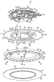
Fig. 1 is the exploded perspective view of representing the lamp of first embodiment from the below.
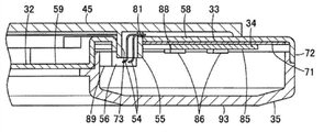
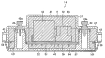
Fig. 2 is the profile of the described lamp of expression.
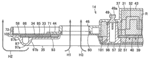
Fig. 3 is the profile of representing the part of described lamp enlargedly.
Fig. 4 is the plane of state of having represented to remove the outer cover of described lamp from the below.
Fig. 5 is the plane of representing the resettlement section of described lamp from the below.
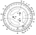
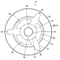
Fig. 6 is the plane of representing described lamp from the below.
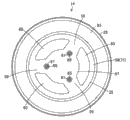
Fig. 7 is the plane of representing described lamp from the top.
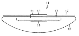
Fig. 8 is the side view that schematically shows the ligthing paraphernalia that comprises the lamp device, and described lamp device comprises described lamp.
Fig. 9 is the exploded perspective view of representing the lamp of second embodiment from the below.
Figure 10 is the profile of representing the part of described lamp enlargedly.
Figure 11 is the profile of representing another part of described lamp enlargedly.
Figure 12 is the plane of representing described lamp from the below.
Figure 13 is the plane of representing described lamp from the top.
Figure 14 is the profile of the lamp of expression the 3rd embodiment.
Figure 15 is the profile of a part of representing the lamp of the 4th embodiment enlargedly.
Figure 16 is the profile of representing another part of described lamp enlargedly.
Figure 17 is the profile of a part of representing the lamp of the 5th embodiment enlargedly.
Figure 18 is the plane of state of having represented to remove the outer cover of described lamp from the below.
Figure 19 is the plane of representing the resettlement section of described lamp from the below.
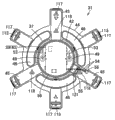
Figure 20 is the plane of representing described lamp from the below.
Figure 21 is the plane of representing described lamp from the top.
Figure 22 is the side view that schematically shows the ligthing paraphernalia of the 6th embodiment.
Reference numeral:
11: ligthing paraphernalia
12: apparatus body
13: lamp socket
The 14:LED lamp
15: the lamp device
16: lampshade
21: the lamp socket body
31: the resettlement section
32: radiator
33: the insulation sheet material
34: as the LED substrate of light source substrate
35: outer cover
37: the resettlement section body
39: lamp circuit
40: power supply board
42: matrix part
43: the matrix protuberance
44: circumference
45: link arm
46: vent openings
48: maintaining part
49: the electrode pin
49a: expansion section
50,117,118: the screw receiving portion
51: the power supply board body
52: electronic component
53,54: distribution
55: distribution is inserted logical portion
56: connector
57: cap
58: configuration portion
59: linking part
60: peristome
61,115: screw
65,76: screw hole
66: by hook portion
67: hook portion
71: configuration is facial
72: bend
73: opening
75,114: as the screw of fixed component
78: card ends opening
81: open communication
82: intercommunicating pore
85: substrate body
86: as the LED of light source
88: cut peristome
89: the connector receiving portion
90,127: through hole
93: covering portion
94: card claw stop portion
96: lid
97: lens section
97a: top
97b: exit facet
98: the press section
101: electrode pin support portion
103: inboard press section
104: press rib
105: planar portions
106: card ends arm
106a: claw
106b: anti-tampering portion
108: card ends peristome
110: protuberance
110a: bottom
113: the support portion
121: the prominent portion that establishes
124: the sheet material extension
126: extension
128: card ends protuberance
C: imaginary circles
H1, H2, H3: arrow
P: plane
R: resin
The specific embodiment
Below, referring to figs. 1 through Fig. 8, the formation of first embodiment is described.
As shown in Figure 8, ligthing paraphernalia 11 comprises: apparatus body 12 is arranged at ceiling surface; Lamp device 15 has lamp socket (socket) 13 and LED lamp 14, and described lamp socket 13 is installed on the central portion of described apparatus body 12 etc., and described LED lamp 14 is the lamps that can be installed on described lamp socket 13 and can break away from described lamp socket 13; And lampshade (globe) 16, described lamp device 15 is covered.Moreover, below about directions such as above-below directions, the state that lamp device 15 is installed with level is benchmark, and apparatus body 12 and lamp socket 13 sides as upside, are described lamp device 15 sides as downside.
In addition, extremely shown in Figure 8 as Fig. 1, LED lamp 14 from upside to downside, be assembled with integratedly resettlement section 31 as lamp shell, as the radiator 32 of metal framework, as the insulation sheet material (sheet) 33 of insulating component, as the light emitting element substrate of light source substrate be LED substrate 34, and as the outer cover 35 of lampshade (lamp globe), and become slim cylindric.
In addition, matrix protuberance 43 has lid cylindric for flat, and diameter dimension is set less than the diameter dimension of matrix part 42.And, LED lamp 14 being installed under the state of lamp socket 13, described matrix protuberance 43 is inserted into the inserting hole of lamp socket body 21.
In addition, each to link arm 45 be from base end side (inboard) distolateral (outside) mode of narrowing down gradually and forming forward with width.In addition, the front of described binding arm 45 projects to the place than the more outer side of the outer peripheral edges of circumference 44.
In addition, lamp circuit 39 be in order to via electrode pin 49,49 and never the electric power supplied with of illustrated external power source (source power supply) change, and to the circuit of LED substrate 34 power supplies.
And power supply board 40 comprises power supply board body 51 and electronic component 52, and remains secured to the maintaining part 48 of the matrix part 42 of resettlement section body 37, and described electronic component 52 is installed on described power supply board body 51 and constitutes lamp circuit 39.Power supply board body 51 is being remained under the state of maintaining part 48, the part of electronic component 52 is chimeric and be positioned at the inside of matrix protuberance 43.And, in described power supply board 40, derive respectively the distribution 53 that electrically connects with each electrode pin 49 is arranged, and with the many distributions 54 of LED substrate 34 electric connections.Described distribution 54 along the resettlement section 31 any link arm 45 configurations, link in the arm 45 at this, insert the distribution that passes to the square tube shape and insert in the logical portion 55, and be directed to LED substrate 34 sides, the distribution of described square tube shape is inserted the logical portion 55 outstanding positions that are arranged at than the more outer side in outer edge of circumference 44.In addition, the front of described distribution 54 is connected in a connector (connector) 56.
In addition, radiator 32 is by metals such as for example aluminium of thermal diffusivity and excellent thermal conductivity and form lamellar.This radiator 32 comprises the cap 57 of toroidal, circular configuration portion 58 and a plurality of linking part 59 integratedly.The cap 57 of toroidal is covered resettlement section 31.Circular configuration portion 58 be positioned at described cap 57 foreign side around.A plurality of linking parts 59 for example have three, form radially along diametric(al), and cap 57 are linked with configuration portion 58.Therefore, in radiator 32, interior all sides of the outer circumferential side of cap 57, configuration portion 58, and linking part 59,59 between, be respectively arranged with peristome 60.And described radiator 32 is fixed in resettlement section 31 by a plurality of screws 61 as the radiator fixed component.
Cap 57 forms the toroidal that the whole resettlement section body 37 with resettlement section 31 is covered.In addition, near the outer peripheral edges portion of described cap 57, in the position corresponding with the cardinal extremity of each linking part 59, be respectively arranged with the screw hole 65 that is inserted by screw 61.Radiator 32 is being installed under the state of resettlement section 31, described screw hole 65 is communicated with the screw receiving portion 50 of resettlement section 31 respectively, and the screw 61 that is inserted into described screw hole 65 is fixed at screw receiving portion 50.And, the outer peripheral edges portion of described cap 57 side that makes progress is outstanding agley, central portion at each peristome 60 of described outer peripheral edges portion, be resettlement section 31 side-prominent being provided with by hook portion 66 to upside respectively, this by hook portion 66 as heat radiation holding section, side with so that radiator 32 stop to rotate with respect to resettlement section 31, and in order to radiator 32 is located.Describedly formed round (loop shape) by hook portion 66, and radiator 32 is being installed under the state of resettlement section 31, be sticked in the hook portion 67 as hook-shaped side holding section, resettlement section respectively, the described hook portion 67 outstanding peripheries that are arranged at the matrix part 42 of resettlement section body 37 as hook-shaped side holding section, resettlement section.
In addition, configuration portion 58 comprises configuration facial 71 and bend 72 integratedly.Configuration facial 71 forms the annulus tabular, and becomes the configuration plane of LED substrate 34.Bend 72 is outstanding agley downwards from the outer peripheral edges of described configuration facial 71.Near the inner peripheral of configuration facial 71, i.e. near position the outer peripheral edges of cap 57 is provided with the opening 73 of square hole shape.In addition, near the outer peripheral edges of described configuration facial 71, be provided with a plurality of screw holes 76, described a plurality of screw holes 76 are fixed in radiator 32 in order to by a plurality of screws 75 as fixed component with LED substrate 34.In addition, the card that is provided with a plurality of square hole shapes in bend 72 ends opening 78, and the card of described a plurality of square hole shapes ends opening 78 in order to outer cover 35 is limited to radiator 32.
In addition, each linking part 59 is parts that the base end side that respectively links arm 45 with resettlement section 31 is covered, and is from base end side (inboard) distolateral (outside) mode of narrowing down gradually and forming forward with width.
In addition, insulation sheet material 33 usefulness form circularly so that radiator 32 insulate with LED substrate 34, and the lower surface of the configuration face 71 of the configuration portion 58 of radiator 32 are covered, and are mounted fixing with LED substrate 34.Described insulation sheet material 33 is set to and disposes facial 71 about equally width dimensions, and the roughly whole lower surface that will dispose face 71 is covered.And, in described insulation sheet material 33, being provided with the open communication 81 of square hole shape in the position of inner peripheral side, the open communication 81 of this square hole shape is communicated with the opening 73 of radiator 32 and inserts logical by each distribution 54.In addition, in described insulation sheet material 33, near the position outer peripheral edges is respectively arranged with the intercommunicating pore 82 that is communicated with each screw hole 76 of radiator 32.
In addition, LED substrate 34 is also referred to as led module (module), and it comprises the flat substrate body 85 of annulus and a plurality of LED86 integratedly, and described a plurality of LED86 are as the light source that is installed on the solid-state light emitting element of described substrate body 85.
In addition, each LED86 is the element that the resin-sealed layer by Yellow luminous system will for example send the surface installation type that the led chip (chip) of blue light covered, and on the row (imaginary circles C) of regulation, roughly equally spaced separate each other and be disposed at the lower surface of substrate body 85, namely with the position of the outer circumferential side of outer cover 35 face in opposite directions.Moreover described imaginary circles C is the circle concentric with substrate body 85, and through hole 90 is positioned on this imaginary circles C.Therefore, the position of LED substrate 34 on described imaginary circles C be fixed in radiator 32 by each screw 75, thereby thermally coupled is in radiator 32.
In addition, outer cover 35 is the plastic outer covers with light transmission, and forms corresponding with the configuration portion 58 of radiator 32 (configuration facial 71) circular.And described outer cover 35 comprises covering portion 93 and the card claw stop portion 94 of annulus band shape integratedly.The covering portion 93 of annulus band shape and the downside (emission side) of LED substrate 34 (LED86) are in opposite directions.Card claw stop portion 94 is arranged at the outer peripheral edges of described covering portion 93 as fastener.And in order to outer cover 35 is limited to radiator 32.
Covering portion 93 forms plane, and is positioned at downwards and LED substrate 34 position spaced.
In addition, card claw stop portion 94 is that the card that is inserted into radiator 32 ends opening 78 and blocked the part of ending, and is formed at the outer peripheral edges of covering portion 93 with being claw-like.
And lampshade 16 is to constitute in such a way, that is, by the synthetic resin with light transmission etc., what form that upside for example forms opening has a round-ended cylinder shape, and LED lamp 14 (lamp device 15) is covered, and makes the light diffusion of sending from LED lamp 14 (LED86).
Then, the effect to described first embodiment describes.
When LED lamp 14 is assembled, at first, power supply board 40 (lamp circuit 39) is inserted into the resettlement section body 37 of the resettlement section 31 that each electrode pin 49 is installed, keep this power supply board 40 (lamp circuit 39) by maintaining part 48, by each distribution 53 each electrode pin 49 and power supply board 40 are electrically connected, described power supply board 40 (lamp circuit 39) is installed on power supply board body 51 with electronic component 52.In addition, drawn on any binding arm 45 from each distribution 54 that power supply board 40 is derived, insert to lead in distribution and insert the downside that leads to portion 55 and export to resettlement section 31.
Then, radiator 32 is installed on described resettlement section 31.At this moment, make the position of each linking part 59 aim at the position that respectively links arm 45 of resettlement section 31 respectively, make the position of each screw receiving portion 50 of position alignment of each screw hole 65, and one side makes each by the position of each hook portion 67 of the position alignment of hook portion 66, one side is pushed into resettlement section 31 sides with radiator 32, whereby, each hook portion 67 is sticked in each by hook portion 66, and radiator 32 temporarily is limited to resettlement section 31.At this moment, insert each distribution 54 and 56 slotting the leading in the opening 73 of the configuration face 71 of configuration portion 58 of connector that logical portion 55 derives from distribution, and export to the downside of this configuration facial 71.Then, screw 61 is inserted into each screw hole 65, and is fixed at each screw receiving portion 50, whereby, radiator 32 is mounted on resettlement section 31.Under described state, covered by the cap 57 of radiator 32 matrix part 42 with the resettlement section body 37 of resettlement section 31, and resettlement section 31 respectively to link the back side that arm 45 is positioned at each linking part 59 be upper surface, and configuration portion 58 be positioned at cap 57 (resettlement section 31) foreign side around.
And then, LED substrate 34 is installed on described radiator 32 across insulation sheet material 33, described LED substrate 34 is installed on substrate body 85 with LED86 and connector receiving portion 89 etc. in advance.At this moment, make the position of opening 73 of position alignment radiator 32 of the open communication 81 of insulation sheet material 33, and make the position of each screw hole 76 of the position alignment radiator 32 of each intercommunicating pore 82.In addition, make the position of the opening 73 of the open communication 81 of position alignment insulation sheet material 33 of incision peristome 88 of substrate body 85 of LED substrate 34 and radiator 32, and make the position of each screw hole 76 of each intercommunicating pore 82 of position alignment insulation sheet material 33 of each through hole 90 and radiator 32.Under described state, screw 75 is inserted into each through hole 90 and each intercommunicating pore 82, and is fixed at each screw hole 76, whereby, LED substrate 34 is mounted on the configuration face 71 of the configuration portion 58 of radiator 32 across insulation sheet material 33.In addition, can derive from the open communication 81 of insulation sheet material 33 and the incision peristome 88 of LED substrate 34 from each distribution 54 and connector 56 that the opening 73 of radiator 32 is derived, connector 56 is connected in connector receiving portion 89, and whereby, lamp circuit 39 electrically connects with each LED86.
Then, described LED substrate 34 is given mulched ground outer cover 35 is installed on radiator 32.At this moment, the position that one side makes each card of the position alignment radiator 32 that respectively blocks claw stop portion 94 end opening 78, one side is pushed into radiator 32 sides with outer cover 35, and whereby, described card claw stop portion 94 is sticked in only opening 78 of card respectively.As a result, the covering portion 93 of outer cover 35 is in the state that each LED86 with LED substrate 34 is covered.
Under the state of the wide diameter portion of the lamp socket opening that each electrode pin 49 is inserted into lamp socket 13, the LED lamp 14 of assembling is in this way rotated along circumferencial direction, whereby, this LED lamp 14 is installed on apparatus body 12, and each electrode pin 49 electrically connects with external power source (source power supply) via pod.Then, LED lamp 14 is given mulched ground lampshade 16 is installed on apparatus body 12, whereby, finish ligthing paraphernalia 11.
By described lamp circuit 39 by lamp socket 13 from external power source (source power supply) is supplied to lamp circuit 39 via each electrode pin 49 electric power is changed, and be supplied to each LED86, described LED86 is lit a lamp.The light that sends from each LED86 spreads by the covering portion 93 of outer cover 35, and by lampshade 16 and diffusion and shining.
Conduct to the cap 57 of the radiator 32 that this lamp circuit 39 is covered from the heat of lamp circuit 39.In addition, from the heat of LED substrate 34 (LED86) from substrate body 85 via insulation sheet material 33, conduct to the configuration portion 58 of radiator 32.Therefore, utilize lamp circuit 39 and LED substrate 34 (LED86), heating region is separated, gather (delay) of local (part) heat is suppressed to Min., and radiator 32 has been guaranteed high surface area by cap 57, thereby will be released in the atmosphere from the heat of LED substrate 34 (LED86) with producing effect.
Particularly radiator 32 produces thermal convection current to interior all sides and the outer circumferential side accepted from the configuration portion 58 of the heat of LED substrate 34 (LED86), and extraneous air passes peristome 60 (vent openings 46 of resettlement section 31) (arrow H1, arrow H2), whereby, dispel the heat in atmosphere, described peristome 60 (vent openings 46 of resettlement section 31) is between the cap 57 that lamp circuit 39 is covered and the configuration portion 58 that disposing LED substrate 34 with producing effect.
As mentioned above, according to described first embodiment, radiator 32 comprises cap 57 and configuration portion 58 integratedly.Cap 57 is covered resettlement section 31, and lamp circuit 39 is being accommodated in this resettlement section 31 in inside.Configuration portion 58 be positioned at described cap 57 around, thermally coupled and disposing LED substrate 34, whereby, can make the heat from lamp circuit 39 and LED substrate 34 (LED86) be dispersed to cap 57 and configuration portion 58, and the surface area of radiator 32 is increased, thereby can utilize simple formation to dispel the heat with producing effect.
Then, with reference to Fig. 9 to Figure 13, second embodiment is described.Moreover, identical symbol is enclosed in formation and the effect identical with described first embodiment, and omitted its explanation.
In the LED of second embodiment lamp 14, resettlement section 31 comprise resettlement section body 37, with the plastic lid 96 of establishing mechanism in addition that this resettlement section body 37 is covered, outer cover 35 comprise the lens section 97 that makes the light diffusion of sending from each LED86 of LED substrate 34, with the press section 98 that LED substrate 34 is pressed on radiator 32.
The screw receiving portion 50 of the resettlement section body 37 of resettlement section 31 is disposed at and respectively links arm 45.In addition, lid 96 forms discoideus, and this is discoideus to be that downside with the matrix part 42 of resettlement section body 37 is covered and with the shape of its obstruction.And, on the top of described lid 96, the outstanding electrode pin support portion 101 that is provided with the sleeve-like that is supporting each electrode pin 49.Therefore, lid 96 forms thermally coupled with this resettlement section body 37 under the state that is installed on resettlement section body 37.In addition, the cap 57 that the lower surface of described lid 96 is planarly with radiator 32 comes in contact, and whole face connects airtight the cap 57 in this radiator 32.
In addition, outer cover 35 namely, in the position corresponding with imaginary circles C, comprises being the lens section 97 that links to each other in covering portion 93 and LED86 LED substrate 34 position in opposite directions circularly.And, described outer cover 35 is formed with inboard press section 103 in the position of the inner peripheral side of lens section 97, and be formed with in the position than the more inner all sides in inboard press section 103 and press rib (rib) 104, described inboard press section 103 is as first press section of a part that forms press section 98, and the described rib 104 of pressing is as second press section of a part that forms press section 98.In addition, ratio lens section 97 at described outer cover 35 more leans on the outer circumferential side place, that is, and and at the outer peripheral edges side place of outer cover 35, spread all over whole circumference ground and be formed with plane planar portions 105 continuously, the configuration face 71 of the configuration portion 58 of this plane planar portions 105 and radiator 32 connects airtight.And, at the inner peripheral of outer cover 35, be radially outstanding to central portion and be provided with a plurality of for example three cards as the outer cover fastener and end arm 106, this card only arm 106 in order to described outer cover 35 is limited to radiator 32.
In addition, press section 98 is to constitute in such a way, namely, radiator 32 is being installed under the state of resettlement section 31, this press section 98 presses on the substrate body 85 of LED substrate 34 the configuration portion 58 (configuration facial 71) of radiator 32, whereby, more positively the heat of LED substrate 34 is conducted to radiator 32 (configuration portion 58).
Inboard press section 103 forms the circular planes shape, and this circular planes shape spreads all over the position that links to each other with the exit facet 97b of interior all sides of lens section 97, namely spread all over lens section 97 inner peripheral whole circumference and link to each other.
In addition, respectively press rib 104 along diametric(al), being the back side that is formed at outer cover 35 radially respectively is upper surface and outstanding, and roughly equally spaced separates each other.
In addition, to be flange (flange) shape ground outstanding and link to each other to the outer circumferential side of lens section 97 for planar portions 105.
And each card ends that arm 106 is outstanding to be arranged at the position corresponding with each linking part 59 of radiator 32, and is from the base end side distolateral mode that narrows down gradually and forming forward with width.In addition, end the top of the front of arm 106 at described card, inwardly the side-prominent claw 106a that is provided with of week.The claw 106a that described card ends arm 106 inserts the card be limited to the square hole shape and ends peristome 108, and the card of this square hole shape ends peristome 108 and is arranged near the outer peripheral edges of cap 57 of each linking part 59 of radiator 32.And, end on the arm 106 at any card, be formed with anti-tampering 106b projectedly to downside, this anti-tampering 106b is in order to the interference between connector receiving portion 89, each distribution 54 and the connector 56 etc. of avoiding and be installed on LED substrate 34.
Then, when outer cover 35 is installed on radiator 32, press section 98 and planar portions 105 etc. is given bonding, whereby, LED substrate 34 is pressed on the configuration portion 58 of radiator 32, and with outer cover 35 thermally coupleds in described LED substrate 34.Under described state, the lens section 97 of outer cover 35 and LED86 (and screw 75) are in opposite directions.That is, screw 75 is positioned at the inboard of the lens section 97 of outer cover 35.
And, owing to can the straight line light from LED86 be spread by lens section 97, therefore, can realize wide luminous intensity distribution, thereby can replace conventional lighting sources to use that described lens section 97 is outstanding to the thickness direction of outer cover 35 opposite to each other with LED86.In addition, utilize press section 98 that LED substrate 34 is pressed on radiator 32, whereby, can more positively LED substrate 34 be fixed in radiator 32, can make the heat from LED substrate 34 (LED86) conduct to radiator 32 with more producing effect, and LED substrate 34 (LED86) directly forms thermally coupled with outer cover 35 across press section 98, also can make from the heat of LED substrate 34 (LED86) and dispel the heat from outer cover 35, therefore, can further suppress the temperature of LED86, and can make the efficient of LED lamp 14 higher.
Moreover, the 3rd embodiment that also can be as shown in figure 14 like this, the cap 57 of the radiator 32 in described second embodiment is made as protuberance 110, and this protuberance 110 is more namely more side-prominent down to the thickness direction of outer cover 35 than lens section 97 (the top 97a of lens section 97).It is plane that the mounting surface of described protuberance 110 is that bottom 110a forms, can with LED lamp 14 stably mounting on plane P.Then, when in this way, with resettlement section 31 sides as upside, by the bottom 110a of protuberance 110 with LED lamp 14 mountings on plane P the time, because protuberance 110 (cap 57) projects to than lens section 97 and locates more on the lower, therefore, lens section 97 can not disturb plane P, can prevent that lens section 97 is injured or damaged.
In addition, also can be as Figure 15 and the 4th embodiment shown in Figure 16, resin R is filled to the inside of the resettlement section 31 in described each embodiment, make the cap 57 of lamp circuit 39 (power supply board 40) and radiator 32 directly form thermally coupleds, described resin R for example is the radiating component that high thermal conductive silicon ketone (silicone) (heat radiation silicone) etc. has thermal diffusivity and thermal conductivity.In said case, to having accepted to produce thermal convection current (arrow H1, arrow H2) from interior all sides of the configuration portion 58 of the radiator 32 of the heat of LED substrate 34 (LED86) and the both direction of outer circumferential side, and from directly having accepted to produce thermal convection current (arrow H3) from the cap 57 of the radiator 32 of the heat of lamp circuit 39 to outer circumferential side.That is, the heat that produces of LED substrate 34 (LED86) and lamp circuit 39 flows into the identical peristome 60 that is arranged between cap 57 and the configuration portion 58 respectively.As a result, the synergistic effect (synergistic effect) when flowing into by heat from described both direction produces more powerful thermal convection current at peristome 60, thereby can will be released into the atmosphere from the heat that LED substrate 34 (LED86) produces with more producing effect.
Then, with reference to Figure 17 to Figure 21, the 5th embodiment is described.Moreover, identical symbol is enclosed in formation and the effect identical with described each embodiment, and omitted its explanation.
The resettlement section 31 of the LED lamp 14 of the 5th embodiment comprises support portion 113 respectively between the binding arm 45,45 of resettlement section body 37, and in lid 96, be provided with distribution and insert logical portion 55, and LED substrate 34 and radiator 32 are by screw 114,115 and be mounted on resettlement section 31, described screw 114, the 115th, the fixed component that shares.
Each support portion 113 from circumference 44 along the resettlement section 31 diametric(al), be outstanding formation radially to foreign side, and be positioned at and link arm 45,45 centre.Therefore, linking arm 45 roughly equally spaced separates each other with support portion 113.In addition, near each support portion 113 reaches the front end that respectively links in the arm 45 position, the outstanding screw receiving portion 117 that is provided with spiral shell set screw 114, and the position of the base end side in each binding arm 45 is respectively given prominence to the screw receiving portion 118 that is provided with spiral shell set screw 115 respectively.
In addition, at lid 96, be embedded in any tongue-shaped prominent portion 121 that establishes that links arm 45 and be outstanding setting the radially along diametric(al), this prominent front of establishing portion 121 extends to till near screw receiving portion 118.And in described prominent front of establishing portion 121, the distribution that forms the square tube shape is inserted logical portion 55.This distribution is inserted logical portion 55 and is inserted into opening 73, and more outer cover 35 sides of lower surface that front projects to than the linking part 59 of described radiator 32 are downside, and described opening 73 is arranged at the position of any linking part 59 of radiator 32.And, establish between portion 121 and the binding arm 45 along prominent, insert to lead in distribution from the distribution 54 of lamp circuit 39 (power supply board 40) and insert logical portion 55, and derive to LED substrate 34 sides.
In addition, in radiator 32, insert the logical screw hole 76 except being provided with by screw 114, also in each linking part 59, be respectively arranged with by screw 115 and insert logical not shown screw hole.
In addition, insulation sheet material 33 respectively links arm 45 and each support portion 113 corresponding to resettlement section 31, is respectively arranged with by screw 114 and inserts logical intercommunicating pores 82.And, described insulation sheet material 33 with inner peripheral respectively link the corresponding position of arm 45, extend respectively and be provided with sheet material extension 124, in described sheet material extension 124, be respectively arranged with by screw 115 and insert logical not shown intercommunicating pores.
In addition, LED substrate 34 with the inner peripheral of substrate body 85 respectively link the corresponding position of arm 45, extend respectively and be provided with extension 126.In addition, in substrate body 85, corresponding to resettlement section 31 respectively link arm 45 and each support portion 113, be respectively arranged with by screw 114 and insert logical through holes 90, and in each extension 126, be provided with by screw 115 and insert logical through holes 127.
In addition, it is outstanding to the foreign side of outer cover 35 that each card of outer cover 35 ends the claw 106a of arm 106, and the card that is limited to round ends protuberance 128, and the card of this round ends protuberance 128 and is erected near the outer peripheral edges of cap 57 of each linking part 59 of radiator 32.
Then, when LED lamp 14 is assembled, at first, power supply board 40 (lamp circuit 39) is inserted the resettlement section body 37 that remains in resettlement section 31, by each distribution 53 each electrode pin 49 and power supply board 40 (lamp circuit 39) are electrically connected.
Then, with the lid 96 chimeric described resettlement section bodies 37 that are installed on.At this moment, will insert to lead in the prominent of lid 96 from each distribution 54 that power supply board 40 (lamp circuit 39) is derived and establish the slotting logical portion 55 of formed distribution the portion 121, and export to the outside (downside) of described lid 96.
Then, radiator 32, insulation sheet material 33 and LED substrate 34 are installed on described resettlement section 31.At this moment, with the intercommunicating pore 82 of the screw hole 76 of radiator 32, insulation sheet material 33, and the position of the through hole 90 of LED substrate 34 aim at the position of each screw receiving portion 117 respectively, and with the not shown intercommunicating pore of the not shown screw hole of radiator 32, insulation sheet material 33, and the position of the through hole 127 of LED substrate 34 aim at the position of each screw receiving portion 118 respectively, fix integratedly by screw 114,115.Under described state, each sheet material extension 124 of insulation sheet material 33 and each extension 126 of LED substrate 34 overlap on each linking part 59 of radiator 32, and than any sheet material extension 124 and any extension 126 more by the position of central portion side, distribution is inserted logical portion 55 and is inserted into opening 73, and each distribution 54 and connector 56 are inserted logical portion 55 by described distribution and be exported.Then, described connector 56 is connected in connector receiving portion 89, whereby, lamp circuit 39 electrically connects with each LED86.
Then, described LED substrate 34 is given mulched ground outer cover 35 is installed on radiator 32.At this moment, the position that each card of the position alignment radiator 32 of each card claw stop portion 94 is ended opening 78, and the position that each card of position alignment radiator 32 that each card is ended the claw 106a of arm 106 ends protuberance 128, simultaneously outer cover 35 is pushed, whereby, each blocks claw stop portion 94 and each claw 106a and is limited to that each card ends opening 78 and each card ends protuberance 128.As a result, the lens section 97 of the covering portion 93 of outer cover 35 becomes each LED86 state in opposite directions with LED substrate 34.
Via each electrode pin 49, the LED lamp 14 of assembling in this way is installed on lamp socket 13 (apparatus body 12), thereby electrically connects with external power source (source power supply), LED lamp 14 is given mulched ground lampshade 16 is installed on apparatus body 12, whereby, finish ligthing paraphernalia 11.
Come following electric power is changed by described lamp circuit 39, and be supplied to each LED86, described LED86 lights a lamp, and described electric power is by lamp socket 13, is supplied to the electric power of lamp circuit 39 via each electrode pin 49 from external power source (source power supply).The light that sends from each LED86 is by the lens section 97 of outer cover 35 and spread, and spreads by lampshade 16, and as the light of homogeneous and shine.
Conduct to the cap 57 of the radiator 32 that this lamp circuit 39 is covered from the heat of lamp circuit 39, from the heat of LED substrate 34 (LED86) from substrate body 85 via insulation sheet material 33, conduct to the configuration portion 58 of radiator 32.Therefore, utilize lamp circuit 39 and LED substrate 34 (LED86), heating region separates, gather (delay) of local (part) heat is suppressed to Min., and radiator 32 has been guaranteed high surface area by cap 57, thereby can will be released in the atmosphere from the heat of LED substrate 34 (LED86) with producing effect.
So, insert logical portion 55 owing in the lid 96 of the tabular simple shape of circle, form distribution, therefore, can easily form distribution and insert logical portion 55, and compare with the situation that the slotting logical portion of distribution is set in the resettlement section of resettlement section 31 body 37, the shape of resettlement section body 37 can be simplified, thereby described resettlement section body 37 can be made at an easy rate.
In addition, owing to by the screw 114,115 that shares, radiator 32, insulation sheet material 33 and LED substrate 34 are fixed in resettlement section 31, therefore, the assembling operation of LED lamp 14 is easy, and can suppress the part number, can realize lightweight and cost degradation.
In addition, according to described second embodiment to the, five embodiments, on the substrate body 85 of LED substrate 34, the position of the row of the LED86 on the row that are disposed at regulation abreast (imaginary circles C), by screw 75 or screw 114 LED substrate 34 is fixed in radiator 32, whereby, the head of screw 75 or screw 114 is positioned at the inboard of lens section 97, and be in and this lens section 97 position in opposite directions, therefore, need not in outer cover 35, to form in order to avoid the formation of the interference between screw 75 or screw 114 and the outer cover 35, can further simplify the formation of outer cover 35, cost is low, and the difficult inequality that produces the light distribution characteristic that is caused by outer cover 35, and owing to the corresponding position of the LED86 with the heating maximum in LED substrate 34, LED substrate 34 is pressed on radiator 32 also fixed, therefore, can will conduct to radiator 32 from the heat of LED86 with more producing effect.
And, resettlement section 31 comprises lid 96, this lid 96 is covered resettlement section body 37, and forming thermally coupleds with described resettlement section body 37, described resettlement section body 37 is being accommodated lamp circuit 39 (power supply board 40) in inside, therefore, the cap 57 of radiator 32 is connected airtight in described lid 96, whereby, can more positively the heat from lamp circuit 39 be conducted to the cap 57 of radiator 32 via lid 96, thereby thermal diffusivity is further improved.
Moreover the 6th embodiment that also can be as shown in figure 22 makes the lampshade 16 in described each embodiment bend to dome shape like this.
In addition, the electronic component 52 of power supply board 40 for example also can only comprise lead (lead) installation part or face is installed part.Only utilizing lead installation part to constitute under the situation of electronic component 52, by the single face that is installed on power supply board body 51, can only utilize a step in the process step that power supply board 40 is installed.In addition, (Surface Mount Device SMD) constitutes under the situation of electronic component 52, can only utilize a step in the process step to form LED substrate 34 and power supply board 40 only utilizing face that part is installed.
And, not only can use LED86 as light source, and (Electroluminescence, EL) element or semiconductor laser solid-state light emitting elements such as (laser) or plane fluorescent lamp etc. are as light source for example can to use organic electroluminescent.
In addition, also the substrate body 85 of LED substrate 34 can be divided into a plurality of parts.
In addition, can at random set the formation that outer cover 35 is installed on radiator 32.In addition, outer cover 35 not necessarily is fixed in radiator 32, for example also can be made as formation that is installed on resettlement section 31 etc.
And according to above at least one embodiment that has illustrated, radiator 32 comprises cap 57 and configuration portion 58 integratedly.Cap 57 is covered resettlement section 31, and lamp circuit 39 is being accommodated in this resettlement section 31 in inside.Configuration portion 58, be positioned at described cap 57 around, thermally coupled and disposing LED substrate 34, whereby, can make the heat from lamp circuit 39 and LED substrate 34 (LED86) be dispersed to cap 57 and configuration portion 58, thereby can prevent that heat is concentrated partly, and the surface area of radiator 32 is increased, can utilize simple formation to dispel the heat with producing effect.Therefore, can tackle the increase of the caloric value of the high efficiency of following LED lamp 14, thereby the efficient of LED lamp 14 is improved.
In addition, the configuration portion 58 from the radiator 32 of the heat of LED substrate 34 (LED86) of having accepted forms circular, and therefore, the both direction of inside all sides and outer circumferential side produces thermal convection current.Therefore, the thermal convection current amount increases significantly, can more dispel the heat with producing effect.And, air is by peristome 60, this peristome 60 forms opening between the cap 57 that lamp circuit 39 is covered of radiator 32 and the configuration portion 58 that disposes LED substrate 34, whereby, can utilize heat radiation and air circulation that the heat dissipation characteristics of radiator 32 is improved, and can realize lightweight and the cost degradation of radiator 32.
And, in the resettlement section 31 that is formed by resin, form distribution and insert logical portion 55, each 54 slotting leading in this distribution of distribution is inserted logical portion 55, described distribution is inserted logical portion 55 and is inserted into opening 73 set in the metal radiator 32, and it is side-prominent to outer cover 35 from this opening 73, described each distribution 54 electrically connects lamp circuit 39 and LED substrate 34, whereby, inserts logical portion 55 by resinous distribution and prevents that each distribution 54 and the edge portion of the opening 73 of metal radiator 32 from disturbing.Therefore, can friction etc. not take place because of the edge portion of each distribution 54 and opening 73 and make each distribution 54 injured, can protect each distribution 54 that broken string etc. does not take place, thereby reliability is further improved.
Some embodiments of the present utility model are illustrated, but these embodiments are the embodiments that are prompted as an example, and the intention that limits of the scope of unmatchful utility model.These novel embodiments can be implemented with other variety of ways, and in the scope of the aim that does not break away from utility model, can carry out various omissions, replacement and change.Described embodiment or its distortion are contained in scope or the aim of utility model, and are contained in the scope impartial with it.
Claims (8)
1. lamp is characterized in that comprising:
Lamp circuit;
The resettlement section comprise the pair of electrodes pin that electrically connects with described lamp circuit, and described lamp circuit is being accommodated in described resettlement section in inside;
Radiator comprises the cap that described resettlement section is covered integratedly and is positioned at described cap configuration portion on every side;
Light source substrate comprises by the electricity of supplying with from described lamp circuit and luminous light source, and described light source substrate thermally coupled and be disposed at the configuration portion of described radiator; And
Outer cover has light transmission, and described outer cover is covered described light source substrate.
2. lamp according to claim 1 is characterized in that: described radiator comprises the peristome that air passes through between described cap and described configuration portion.
3. lamp according to claim 1 and 2 is characterized in that:
Described outer cover comprises
Lens section, outstanding to thickness direction opposite to each other with described light source, and make the light diffusion of sending from described light source; And
The press section presses on described radiator with described light source substrate.
4. lamp according to claim 3 is characterized in that: described cap is more outstanding to the thickness direction of described outer cover than described lens section.
5. lamp according to claim 3 is characterized in that:
The described light source of described light source substrate is configured in listing of regulation abreast,
Described lamp comprises fixed component, and described fixed component is fixed in described radiator in the position of the row of described light source with described light source substrate, and is equipped on the inboard of described lens section.
6. lamp according to claim 1 and 2 is characterized in that:
Described radiator comprises opening,
Described resettlement section is formed by resin and comprises the slotting logical portion of distribution, and the slotting logical portion of described distribution is inserted into described opening and is outstanding from described opening to described jacket side, and
The distribution that electrically connects described lamp circuit and described light source substrate is inserted the slotting logical portion of described distribution that passes to.
7. lamp device is characterized in that comprising:
Lamp socket; And
According to each described lamp in the claim 1 to 6, the described electrode pin of described lamp is connected in described lamp socket.
8. ligthing paraphernalia is characterized in that comprising:
Apparatus body;
Lamp device according to claim 7, the described lamp socket of described lamp device is disposed at described apparatus body; And
Lampshade is covered the described lamp of described lamp device.
Applications Claiming Priority (2)
| Application Number | Priority Date | Filing Date | Title |
|---|---|---|---|
| JP2012-168896 | 2012-07-30 | ||
| JP2012168896A JP5825489B2 (en) | 2012-07-30 | 2012-07-30 | Lamp, lamp device and lighting apparatus |
Publications (1)
| Publication Number | Publication Date |
|---|---|
| CN203115583U true CN203115583U (en) | 2013-08-07 |
Family
ID=47602770
Family Applications (1)
| Application Number | Title | Priority Date | Filing Date |
|---|---|---|---|
| CN2013200463377U Expired - Lifetime CN203115583U (en) | 2012-07-30 | 2013-01-28 | Lamp, lamp device and lighting fixture |
Country Status (4)
| Country | Link |
|---|---|
| US (1) | US20140029252A1 (en) |
| EP (1) | EP2693116A1 (en) |
| JP (1) | JP5825489B2 (en) |
| CN (1) | CN203115583U (en) |
Cited By (5)
| Publication number | Priority date | Publication date | Assignee | Title |
|---|---|---|---|---|
| CN107044621A (en) * | 2016-02-05 | 2017-08-15 | 宁波福泰电器有限公司 | Light fixture and its heat dissipating method and manufacture method |
| CN108779900A (en) * | 2016-03-05 | 2018-11-09 | 爱丽思欧雅玛株式会社 | Lighting device |
| CN111386425A (en) * | 2018-04-27 | 2020-07-07 | 萤光勒克斯株式会社 | Lighting device |
| CN113028212A (en) * | 2021-03-01 | 2021-06-25 | 北谷电子有限公司 | Detachable controller and assembling method of detachable controller |
| TWI748190B (en) * | 2018-06-01 | 2021-12-01 | 日商松下知識產權經營股份有限公司 | Lighting fixtures |
Families Citing this family (17)
| Publication number | Priority date | Publication date | Assignee | Title |
|---|---|---|---|---|
| CN203298117U (en) * | 2012-08-31 | 2013-11-20 | 小泉照明株式会社 | Illumination appliance |
| US20140198496A1 (en) * | 2013-01-14 | 2014-07-17 | Wintek Corporation | Illumination apparatus |
| US20150085466A1 (en) * | 2013-09-24 | 2015-03-26 | Intematix Corporation | Low profile led-based lighting arrangements |
| US20150231512A1 (en) * | 2014-02-14 | 2015-08-20 | Brand 44 Trading, Llc | Illuminated device |
| JP6202441B2 (en) * | 2014-02-20 | 2017-09-27 | パナソニックIpマネジメント株式会社 | LED lighting fixtures |
| ES2618480T3 (en) * | 2014-02-24 | 2017-06-21 | Lunux Gmbh | Lighting unit |
| JP6417609B2 (en) * | 2014-09-08 | 2018-11-07 | コイズミ照明株式会社 | lighting equipment |
| JP6459662B2 (en) * | 2015-03-12 | 2019-01-30 | パナソニックIpマネジメント株式会社 | lighting equipment |
| US10041654B1 (en) * | 2015-11-16 | 2018-08-07 | Cooper Technologies Company | Adjustable lighting finishing structure |
| WO2017092624A1 (en) * | 2015-12-03 | 2017-06-08 | 欧普照明股份有限公司 | Optical element, illuminating module and illuminator with the illuminating module |
| WO2017206164A1 (en) * | 2016-06-03 | 2017-12-07 | 东莞励国照明有限公司 | Ceiling lamp provided with light guide plate, and mounting method therefor |
| US10859248B2 (en) * | 2016-10-26 | 2020-12-08 | Opple Lighting Co., Ltd. | Light source module and lighting device |
| CN109952468B (en) | 2016-11-22 | 2021-10-12 | 昕诺飞控股有限公司 | Cover of LED illuminator |
| JP2018206493A (en) * | 2017-05-30 | 2018-12-27 | ルナライト株式会社 | Resin molding component, electronic circuit device and ring-shaped illumination case |
| CN207921861U (en) * | 2017-12-28 | 2018-09-28 | 欧普照明股份有限公司 | A kind of light source module group and lighting device |
| CN207750864U (en) * | 2018-01-22 | 2018-08-21 | 亮信灯饰(深圳)有限公司 | Light bulb |
| DE102022104482A1 (en) * | 2022-02-24 | 2023-08-24 | LUNITE GmbH | Modular lighting unit |
Family Cites Families (10)
| Publication number | Priority date | Publication date | Assignee | Title |
|---|---|---|---|---|
| JPWO2009044716A1 (en) * | 2007-10-01 | 2011-02-10 | 株式会社光波 | Light emitting device |
| TW200940881A (en) * | 2008-03-18 | 2009-10-01 | Pan Jit Internat Inc | LED lamp with thermal convection and thermal conduction heat dissipating effect, and heat dissipation module thereof |
| JP5216447B2 (en) * | 2008-07-03 | 2013-06-19 | パナソニック株式会社 | lamp |
| JP5477530B2 (en) * | 2008-11-28 | 2014-04-23 | 東芝ライテック株式会社 | lighting equipment |
| WO2010088303A1 (en) * | 2009-01-28 | 2010-08-05 | Guy Vaccaro | Heat sink for passive cooling of a lamp |
| CN101865374B (en) * | 2009-02-19 | 2014-05-07 | 东芝照明技术株式会社 | Lamp system and lighting apparatus |
| US8525395B2 (en) * | 2010-02-05 | 2013-09-03 | Litetronics International, Inc. | Multi-component LED lamp |
| DE102010028481A1 (en) * | 2010-05-03 | 2011-11-03 | Osram Gesellschaft mit beschränkter Haftung | Electronic housing for a lamp, semiconductor lamp and method for casting an electronics housing for a lamp |
| JP2012104476A (en) * | 2010-10-12 | 2012-05-31 | Toshiba Lighting & Technology Corp | Lighting device |
| RU2583901C2 (en) * | 2011-01-14 | 2016-05-10 | Конинклейке Филипс Электроникс Н.В. | Lighting fixture |
-
2012
- 2012-07-30 JP JP2012168896A patent/JP5825489B2/en active Active
- 2012-10-24 EP EP12189798.7A patent/EP2693116A1/en not_active Withdrawn
- 2012-10-30 US US13/664,075 patent/US20140029252A1/en not_active Abandoned
-
2013
- 2013-01-28 CN CN2013200463377U patent/CN203115583U/en not_active Expired - Lifetime
Cited By (5)
| Publication number | Priority date | Publication date | Assignee | Title |
|---|---|---|---|---|
| CN107044621A (en) * | 2016-02-05 | 2017-08-15 | 宁波福泰电器有限公司 | Light fixture and its heat dissipating method and manufacture method |
| CN108779900A (en) * | 2016-03-05 | 2018-11-09 | 爱丽思欧雅玛株式会社 | Lighting device |
| CN111386425A (en) * | 2018-04-27 | 2020-07-07 | 萤光勒克斯株式会社 | Lighting device |
| TWI748190B (en) * | 2018-06-01 | 2021-12-01 | 日商松下知識產權經營股份有限公司 | Lighting fixtures |
| CN113028212A (en) * | 2021-03-01 | 2021-06-25 | 北谷电子有限公司 | Detachable controller and assembling method of detachable controller |
Also Published As
| Publication number | Publication date |
|---|---|
| JP2014026942A (en) | 2014-02-06 |
| US20140029252A1 (en) | 2014-01-30 |
| JP5825489B2 (en) | 2015-12-02 |
| EP2693116A1 (en) | 2014-02-05 |
Similar Documents
| Publication | Publication Date | Title |
|---|---|---|
| CN203115583U (en) | Lamp, lamp device and lighting fixture | |
| US8525395B2 (en) | Multi-component LED lamp | |
| JP5218751B2 (en) | Light bulb lamp | |
| TWI424131B (en) | Lighting device | |
| US8534867B1 (en) | LED light modules and outdoor light fixtures incorporating such light modules | |
| KR101135721B1 (en) | Socket-typed LED light apparatus | |
| CN205037079U (en) | Light -emitting diode (LED) lighting device | |
| KR20140038116A (en) | Led lamp | |
| CN102308143A (en) | Lamp and illumination apparatus | |
| CN102725579A (en) | Light source device | |
| CN104019384B (en) | Lighting device | |
| US20120236552A1 (en) | Linear Lamp | |
| CN102563407B (en) | Luminaire | |
| TWI570357B (en) | The heat lamp using LED bulb | |
| CN103968279A (en) | Lamp Device, Light-Emitting Device and Luminaire | |
| KR100980845B1 (en) | Led module having cooling flow path | |
| KR101072584B1 (en) | Led lighting lamp | |
| CN101382273A (en) | LED lamp with heat radiation structure | |
| US9217563B2 (en) | LED lighting assembly having electrically conductive heat sink for providing power directly to an LED light source | |
| KR20130015724A (en) | Led lamp for lighting | |
| CN201555069U (en) | Efficient heat-dissipation type LED lamp | |
| CN103672635B (en) | LED light device | |
| CN202598185U (en) | Lamp device and illumination device | |
| CN204227103U (en) | Lamp device and lighting device | |
| CN103104841B (en) | Light-emitting diode (LED) lamp unit with high heat-radiating performance and modular high-power LED lamp thereof |
Legal Events
| Date | Code | Title | Description |
|---|---|---|---|
| C14 | Grant of patent or utility model | ||
| GR01 | Patent grant | ||
| CX01 | Expiry of patent term | ||
| CX01 | Expiry of patent term |
Granted publication date: 20130807 |