CN203031782U - 干式取芯钻头 - Google Patents
干式取芯钻头 Download PDFInfo
- Publication number
- CN203031782U CN203031782U CN 201320040419 CN201320040419U CN203031782U CN 203031782 U CN203031782 U CN 203031782U CN 201320040419 CN201320040419 CN 201320040419 CN 201320040419 U CN201320040419 U CN 201320040419U CN 203031782 U CN203031782 U CN 203031782U
- Authority
- CN
- China
- Prior art keywords
- coring bit
- core pipe
- dry
- type coring
- chip area
- Prior art date
- Legal status (The legal status is an assumption and is not a legal conclusion. Google has not performed a legal analysis and makes no representation as to the accuracy of the status listed.)
- Expired - Fee Related
Links
- XLYOFNOQVPJJNP-UHFFFAOYSA-N water Substances O XLYOFNOQVPJJNP-UHFFFAOYSA-N 0.000 abstract description 6
- 238000004140 cleaning Methods 0.000 abstract description 3
- 238000001816 cooling Methods 0.000 abstract description 3
- 238000000034 method Methods 0.000 abstract description 3
- 230000009977 dual effect Effects 0.000 abstract 1
- 229910003460 diamond Inorganic materials 0.000 description 3
- 239000010432 diamond Substances 0.000 description 3
- 230000009286 beneficial effect Effects 0.000 description 1
- 238000010586 diagram Methods 0.000 description 1
- 230000000694 effects Effects 0.000 description 1
- 238000013467 fragmentation Methods 0.000 description 1
- 238000006062 fragmentation reaction Methods 0.000 description 1
- 239000011435 rock Substances 0.000 description 1
Images
Landscapes
- Processing Of Stones Or Stones Resemblance Materials (AREA)
Abstract
本实用新型干式取芯钻头,包括芯管(1)和固接在芯管端部的刀头(2),所述芯管(3)的管外壁上对称分布有若干个沿芯管径向凹入的排屑槽(3)。充分利用对称分布在芯管(3)的管外壁上的排屑槽能很好地解决力的冲击,实现排屑与冷却双重功能。进而提供一种使用方便快捷、且在使用过程中无水渍,不会增加清理劳动量的干式取芯钻头。
Description
技术领域
本实用新型涉及取芯钻头,特别涉及一种干式取芯钻头。
背景技术
取芯钻头又叫空心钻头,目前现有的取芯钻头是带水作业,在使用的过程中会对墙体墙面污染严重,在钻孔作业结束后,对墙体墙面的水渍清理很麻烦,尤其在电子类工厂都安装防静电地板,带水开孔会损坏地板与电子产品,且在钻孔过程中用水冷却而造成的水渍难以清理。
发明内容
本实用新型的目的是:提供一种使用方便快捷、且在使用过程中无水渍,不会增加清理劳动量。
本实用新型干式取芯钻头,包括芯管和固接在芯管端部的刀头,所述芯管的管外壁上对称分布有若干个沿芯管径向凹入的排屑槽。
作为本实用新型的进一步改进,所述所述排屑槽有4个。
作为本实用新型的进一步改进,所述排屑槽为叉形。
综上所述,本实用新型的有益效果是:采用在芯管的管外壁上对称分布有若干个沿芯管径向凹入的排屑槽,充分利用了对称分布在芯管的管外壁上的排屑槽能很好地解决力的冲击,实现排屑与冷却双重功能;且采用叉形排屑槽在使用中产生的回旋风进行冷却,减小冲击力方便了排屑。
附图说明
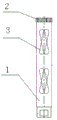
图1是本实用新型的示意图;
图中:1 芯管,2 刀头,3 排屑槽。
具体实施方式
下面结合具体实施方式对本发明做进一步说明:
如图1所示,本实施例包括:芯管1和固接在芯管端部的刀头2,所述芯管3的管外壁上对称分布有若干个沿芯管径向凹入的排屑槽3。本实施例中排屑槽3有4个;且所述的排屑槽3为叉形。
以采用干式取芯钻头对混凝土进行钻孔作业为例,利用排屑槽将钻除的碎屑排出,同时利用钻头的排屑槽在高速旋转状态下,产生的回旋风使金刚石刀头迅速冷却,使混凝土产生弹性变形,此时产生拉伸裂隙,然后形成剪切裂隙和剪切体,金刚石沿着先前金刚石破碎的岩层滑动,产生的切削残渣从排屑槽排出,最后钻头因拉伸应力作用使变得松软的混凝土进行钻孔取芯。
Claims (3)
1.干式取芯钻头,包括芯管(1)和固接在芯管端部的刀头(2),其特征在于所述芯管(3)的管外壁上对称分布有若干个沿芯管径向凹入的排屑槽(3)。
2.根据权利要求1所述的干式取芯钻头,其特征在于所述排屑槽(3)有4个。
3.根据权利要求1所述的干式取芯钻头,其特征在于所述排屑槽(3)为叉形。
Priority Applications (1)
| Application Number | Priority Date | Filing Date | Title |
|---|---|---|---|
| CN 201320040419 CN203031782U (zh) | 2013-01-25 | 2013-01-25 | 干式取芯钻头 |
Applications Claiming Priority (1)
| Application Number | Priority Date | Filing Date | Title |
|---|---|---|---|
| CN 201320040419 CN203031782U (zh) | 2013-01-25 | 2013-01-25 | 干式取芯钻头 |
Publications (1)
| Publication Number | Publication Date |
|---|---|
| CN203031782U true CN203031782U (zh) | 2013-07-03 |
Family
ID=48683923
Family Applications (1)
| Application Number | Title | Priority Date | Filing Date |
|---|---|---|---|
| CN 201320040419 Expired - Fee Related CN203031782U (zh) | 2013-01-25 | 2013-01-25 | 干式取芯钻头 |
Country Status (1)
| Country | Link |
|---|---|
| CN (1) | CN203031782U (zh) |
-
2013
- 2013-01-25 CN CN 201320040419 patent/CN203031782U/zh not_active Expired - Fee Related
Similar Documents
| Publication | Publication Date | Title |
|---|---|---|
| CN203308413U (zh) | 软硬互层岩体大直径钻孔取芯装置 | |
| CN104632073A (zh) | 一种贯通式潜孔锤反循环钻进方法 | |
| CN104278950A (zh) | 双工位液压冲击回转钻进、旋喷动力头 | |
| CN203066865U (zh) | 一种可扩孔的锚杆钻头 | |
| CN106677707A (zh) | 一种空气反循环连续取心冰钻钻头 | |
| CN203145829U (zh) | 基于锚索钻机的小孔径钻孔与水力割缝一体化装置 | |
| CN203702026U (zh) | 钻机钻杆螺旋排渣机构 | |
| CN204283211U (zh) | 极破碎富水软弱围岩隧道超前支护管棚成孔系统 | |
| CN203201471U (zh) | 一种干式取芯钻头 | |
| CN201786305U (zh) | 一种从钻孔中取出牙轮钻杆的工具 | |
| CN203081286U (zh) | 防塌孔钻具 | |
| CN203420640U (zh) | 一种带有加长型喷嘴的pdc钻头 | |
| CN203669758U (zh) | 一种中硬塑性地层快速钻进pdc钻头 | |
| CN201771458U (zh) | 一种扩井打捞装置 | |
| CN203685013U (zh) | 一种一次切槽的装置 | |
| CN203171024U (zh) | 一种自带清渣器的钻头 | |
| CN203614040U (zh) | 一种取心钻头 | |
| CN102628335A (zh) | 冲击钻冲槽机 | |
| CN202731756U (zh) | 一种金刚石复合片内凹钻头 | |
| CN102322217A (zh) | 大直径钻孔灌注桩岩层地段二次成孔方法 | |
| CN203925302U (zh) | 一种适用于极硬地层钻井的七刀翼pdc钻头 | |
| CN202170751U (zh) | 手持式地锚钻机 | |
| CN204703759U (zh) | 岩石劈裂机头装置 | |
| CN204826712U (zh) | 一种可快速凿除的地下连续墙结构 | |
| CN206581893U (zh) | 一种空气反循环连续取心冰钻钻头 |
Legal Events
| Date | Code | Title | Description |
|---|---|---|---|
| C14 | Grant of patent or utility model | ||
| GR01 | Patent grant | ||
| C17 | Cessation of patent right | ||
| CF01 | Termination of patent right due to non-payment of annual fee |
Granted publication date: 20130703 Termination date: 20140125 |