CN202910564U - Multifunctional numerical control machine tool - Google Patents
Multifunctional numerical control machine tool Download PDFInfo
- Publication number
- CN202910564U CN202910564U CN 201220537422 CN201220537422U CN202910564U CN 202910564 U CN202910564 U CN 202910564U CN 201220537422 CN201220537422 CN 201220537422 CN 201220537422 U CN201220537422 U CN 201220537422U CN 202910564 U CN202910564 U CN 202910564U
- Authority
- CN
- China
- Prior art keywords
- head
- numerical control
- milling head
- slide
- slide carriage
- Prior art date
- Legal status (The legal status is an assumption and is not a legal conclusion. Google has not performed a legal analysis and makes no representation as to the accuracy of the status listed.)
- Expired - Fee Related
Links
Images

Abstract
The utility model relates to a multifunctional numerical control machine tool which is provided with double beams, four movable structures, a movable gantry, a fixed worktable, a right-angle milling head and a universal milling head. The right-angle milling head and the universal milling head are provided with precision numerical control boring heads controlled by a numerical control system, radial movement of the precision numerical control boring heads is automatically adjusted, and complicated shapes such as holes, grooves, stepped holes, taper holes, circular arcs and threads are automatically cut by programming. The multifunctional numerical control machine tool is reasonable in structural design, five surfaces of a part can be bored, milled, grinded and the like in various modes by one-step clamping, resource utilization rate is high, time and labor are saved, labor intensity is reduced, machining efficiency and precision are improved, and machining range is widened by the aid of numerical control reducing technology.
Description
Technical field
The utility model relates to Digit Control Machine Tool, specifically has the multifunctional numerical control machine of boring and milling mill function.
Background technology
At present, known lathe only has a kind of function mostly, the function that only has milling such as milling machine, grinding machine only has grinding function, and manufacturing complex shapes is comparatively difficult, and process component need to minute order be processed at different lathes, needs repeated clamping, working (machining) efficiency is low, and the part crudy is unstable.Especially when the machining large part, this deficiency seems particularly evident.Therefore inventing a kind of multifunction numerical control machine is highly profitable.
Summary of the invention
[0003] the purpose of this utility model is exactly the defective for prior art, and a kind of multifunctional numerical control machine that can carry out simultaneously multistage manufacturing processes is provided, and it can carry out boring to workpiece, mill, grinds processing, can improve working (machining) efficiency and machining accuracy again.
The utility model is achieved through the following technical solutions: it comprises bed piece and the slide that is contained on the lathe bed, be provided with workbench in the middle of the lathe bed, slide is provided with crossbeam, crossbeam is provided with slide carriage, ram cutter head is installed on the slide carriage, surface wheel head and omnipotent vertical grinding head, ram cutter head is provided with right-angle milling head and universal milling head, it is characterized in that: two crossbeams are installed on the slide, all be provided with milling head slide carriage and bistrique slide carriage on two crossbeam positive and negatives, the milling head slide carriage is provided with two ram cutter heads, the bistrique slide carriage has been installed a surface wheel head and an omnipotent vertical grinding head, and two ram cutter heads are provided with right-angle milling head and universal milling head.
Described slide and crossbeam form two gantry-travelling frameworks, in the middle of workbench is fixed on; Described lathe bed both sides are equipped with tooth bar, and slide is provided with gear, the rack and pinion engagement, and rack and pinion drives by synchronous servo motor, and above-mentioned two servomotors are to adopt the synchronizing shaft technology to control by CNC; On described right-angle milling head and the universal milling head accurate digital control boring head is installed, accurate digital control boring head is controlled by CNC.
The beneficial effects of the utility model are: adopt the movable gantry structure, workbench is fixed, and lathe bed, workbench length can be made as required, and the workbench bearing capacity strengthens greatly, is more suitable in the processing of super large, overlength, superduty part.Adopt two gantry structures, both can independently process, the processing that can cooperate has again improved working (machining) efficiency greatly, saves manufacturing cost.Adopt two milling heads, plane and omnipotent vertical grinding head four-head structure, realize a tractor serves several purposes, carry out the multiple operation operation, save the clamping time, improve working (machining) efficiency and machining accuracy.Adopt the constant current closed hydrostatic slideway, have the characteristics such as bearing capacity is high, motion is steady, coefficient of friction is little, the absorbing performance is good.Adopt the accurate digital control boring head technology, axially-movable is converted into the radial motion of boring head by CNC control, realize the complicated shapes such as the automatic boring processing shoulder hole of programming, taper hole, groove, circular arc, screw thread.
Below in conjunction with description of drawings and the specific embodiment utility model is further described.
Description of drawings
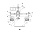
Fig. 1 is structural front view of the present utility model.
Fig. 2 is structure left view of the present utility model.
Among the figure: 1. accurate digital control boring head, 2. right-angle milling head, 3. precision boring head is adjusted servopackage, 4. lathe bed, 5. tooth bar, 6. gear, 7. slide, 8. first crossbeam, 9.Z1 spindle balance oil cylinder, 10.Z1 axle servopackage, 11. the first ram cutter head, 12.Z1 axle slide carriage, 13.Y1 axle servopackage, 14. workbench, 15. universal milling head, 16.Y4 axle servopackage, 17. the second ram cutter head, 18.Z4 axle slide carriage, 19.Z4 spindle balance oil cylinder, 20.Z4 axle servopackage, 21. railing, 22.Z3 axle servopackage, 23. second cross beam, 24.Z3 axle slide carriage, 25.Z3 axle slide plate, 26.Y3 axle servopackage, 27. surface wheel head, 28.X2 axle servopackage, 29.X1 axle servopackage, 30. omnipotent vertical grinding head, 31.Y2 axle servopackage, 32.Z2 axle slide carriage, 33.Z2 axle slide plate, 34.Z2 axle servopackage.
The specific embodiment
Such as Fig. 1, shown in Figure 2, the utility model comprises bed piece 4 and the slide 7 that is contained on the lathe bed, be provided with workbench 14 in the middle of the lathe bed, slide 7 is provided with crossbeam, crossbeam is provided with slide carriage, ram cutter head is installed on the slide carriage, surface wheel head and omnipotent vertical grinding head, ram cutter head is provided with right-angle milling head and universal milling head 15, two crossbeams are installed on the slide, they are first crossbeam 8 and second cross beam 23, first crossbeam 8 and second cross beam 23 are just, all be provided with milling head slide carriage and bistrique slide carriage on the reverse side, the milling head slide carriage is provided with two ram cutter heads, they are the first ram cutter head 11 and the second ram cutter head 17, and the bistrique slide carriage has been installed by a surface wheel head 27 and 30, two ram cutter heads 11 of an omnipotent vertical grinding head and 17 are provided with right-angle milling head 2 and universal milling head 15.Described slide 7 and crossbeam form two gantry-travelling frameworks, in the middle of workbench 14 is fixed on; Described lathe bed both sides are equipped with tooth bar 5, and slide 7 is provided with gear 7, tooth bar 5 and gear 7 engagements, and tooth bar 5 and gear 7 drive by synchronous servo motor, and above-mentioned two servomotors are to adopt the synchronizing shaft technology to control by CNC; On described right-angle milling head 2 and the universal milling head 15 accurate digital control boring head 1 is installed, accurate digital control boring head is controlled by CNC.
Operation principle of the present utility model and mode are as follows:
X-axis motion mode, first crossbeam 8 form gantry frame with slide 7 and drive by X1 axle servopackage 29, and gear 6 is along tooth bar 5 moving linearlies on lathe bed 4; Second cross beam 23 becomes gantry frame to drive by X2 axle servopackage 28 with 7 grades of slides, gear 6 is along tooth bar 5 moving linearlies on lathe bed 4.
The Y-axis motion mode: Y1 axle servopackage 13, Y2 axle servopackage 31, Y3 axle servopackage 26, Y4 axle servopackage 16 drive respectively Z1 axle slide carriage 12 and the first ram cutter head 11, Z2 axle slide carriage 32 and omnipotent vertical grinding head 30, Z3 axle slide carriage 24 and surface wheel head 27, Z4 axle slide carriage 18 and the second ram cutter head 17 moving linearly on first crossbeam 8 and second cross beam 23.
The Z axis motion mode: the first ram cutter head 11 drives moving linearly in Z1 axle slide carriage 12 grooves by Z1 axle servopackage 10; Z2 axle slide plate 33 and omnipotent vertical grinding head 30 drive moving linearly in Z2 axle slide carriage 32 grooves by Z2 axle servopackage 34; Z3 axle slide plate 25 and surface wheel head 27 drive moving linearly in Z3 axle slide carriage 24 grooves by Z3 axle servopackage 22; The second ram cutter head 17 drives moving linearly in Z4 axle slide carriage 18 grooves by Z4 axle servopackage 20.
Accurate digital control boring head 1 is installed on right-angle milling head 2 and the universal milling head 15 and rotates, and adjusts servopackage 3 by precision boring head and regulates its radial motion.Part to be processed is installed on the workbench 14, by CNC and servopackage control, realizes that dynamic head main spindle rotates, two gantry cooperate or do not cooperate, X-axis, Y-axis, Z axis and accurate digital control boring head boring axle link or do not link, and realize automatically control machining of programming, processing parts.
Claims (4)
1. multifunctional numerical control machine, it comprises bed piece and the slide that is contained on the lathe bed, be provided with workbench in the middle of the lathe bed, slide is provided with crossbeam, crossbeam is provided with slide carriage, ram cutter head is installed on the slide carriage, surface wheel head and omnipotent vertical grinding head, ram cutter head is provided with right-angle milling head and universal milling head, it is characterized in that: two crossbeams are installed on the slide, all be provided with milling head slide carriage and bistrique slide carriage on two crossbeam positive and negatives, the milling head slide carriage is provided with two ram cutter heads, and the bistrique slide carriage has been installed a surface wheel head and an omnipotent vertical grinding head, and two ram cutter heads are provided with right-angle milling head and universal milling head.
2. multifunctional numerical control machine according to claim 1 is characterized in that: described slide and crossbeam form two gantry-travelling frameworks, in the middle of workbench is fixed on.
3. multifunctional numerical control machine according to claim 1, it is characterized in that: described lathe bed both sides are equipped with tooth bar, and slide is provided with gear, the rack and pinion engagement, rack and pinion drives by synchronous servo motor.
4. multifunctional numerical control machine according to claim 1, it is characterized in that: on described right-angle milling head and the universal milling head accurate digital control boring head is installed, accurate digital control boring head is controlled by CNC.
Priority Applications (1)
| Application Number | Priority Date | Filing Date | Title |
|---|---|---|---|
| CN 201220537422 CN202910564U (en) | 2012-10-20 | 2012-10-20 | Multifunctional numerical control machine tool |
Applications Claiming Priority (1)
| Application Number | Priority Date | Filing Date | Title |
|---|---|---|---|
| CN 201220537422 CN202910564U (en) | 2012-10-20 | 2012-10-20 | Multifunctional numerical control machine tool |
Publications (1)
| Publication Number | Publication Date |
|---|---|
| CN202910564U true CN202910564U (en) | 2013-05-01 |
Family
ID=48158909
Family Applications (1)
| Application Number | Title | Priority Date | Filing Date |
|---|---|---|---|
| CN 201220537422 Expired - Fee Related CN202910564U (en) | 2012-10-20 | 2012-10-20 | Multifunctional numerical control machine tool |
Country Status (1)
| Country | Link |
|---|---|
| CN (1) | CN202910564U (en) |
Cited By (4)
| Publication number | Priority date | Publication date | Assignee | Title |
|---|---|---|---|---|
| CN103358789A (en) * | 2013-06-28 | 2013-10-23 | 宁波天艺数控机械有限公司 | Numerically controlled jadeware engraving, milling and polishing machine tool |
| CN104475837A (en) * | 2014-11-22 | 2015-04-01 | 宁波市凯博数控机械有限公司 | Numerical control milling machine realizing moving of gantry under driving of gear and rack |
| CN106964990A (en) * | 2017-02-28 | 2017-07-21 | 常熟市双月机械有限公司 | A kind of multifunctional grinder |
| CN112792385A (en) * | 2021-02-10 | 2021-05-14 | 宁波昌成数控机械有限公司 | Long-stroke high-precision numerical control planer type milling machine |
-
2012
- 2012-10-20 CN CN 201220537422 patent/CN202910564U/en not_active Expired - Fee Related
Cited By (4)
| Publication number | Priority date | Publication date | Assignee | Title |
|---|---|---|---|---|
| CN103358789A (en) * | 2013-06-28 | 2013-10-23 | 宁波天艺数控机械有限公司 | Numerically controlled jadeware engraving, milling and polishing machine tool |
| CN104475837A (en) * | 2014-11-22 | 2015-04-01 | 宁波市凯博数控机械有限公司 | Numerical control milling machine realizing moving of gantry under driving of gear and rack |
| CN106964990A (en) * | 2017-02-28 | 2017-07-21 | 常熟市双月机械有限公司 | A kind of multifunctional grinder |
| CN112792385A (en) * | 2021-02-10 | 2021-05-14 | 宁波昌成数控机械有限公司 | Long-stroke high-precision numerical control planer type milling machine |
Similar Documents
| Publication | Publication Date | Title |
|---|---|---|
| CN102380625B (en) | Special numerically controlled lathe for cutting inner arc curved surface | |
| CN201102093Y (en) | Three-axis numerical control panoramic table miller | |
| CN201579591U (en) | Turn-milling-grinding combined machine | |
| CN102151883A (en) | Multihead synchronous or asynchronous carving (drilling) milling numerical control processing equipment | |
| CN107052802B (en) | Turning and milling composite machine tool | |
| CN104117858A (en) | Five-axis linkage vertical machining centre | |
| CN103350343A (en) | Numerical control gantry vertical and horizontal combined machining center of combination of tool magazine and main shaft on saddle | |
| CN202910564U (en) | Multifunctional numerical control machine tool | |
| CN201596896U (en) | Double-beam four-action numerically controlled boring and milling grinder | |
| CN209407521U (en) | A kind of five axis gantry carving and milling machines | |
| CN103182655B (en) | Multi-cutter process valve numerical control double-slider unit head | |
| CN113814733A (en) | Vertical turning and milling combined machining center | |
| CN215999431U (en) | Vertical turning and milling combined machining center | |
| CN203125227U (en) | Numerical control double-slider power head of multi-cutter processing valve body | |
| CN202240452U (en) | Boring mill of numerical control vehicle for brake valve sealing surface | |
| CN204673092U (en) | High-accuracy high-efficiency herringbone bear machining tool | |
| CN202684612U (en) | Numerical control gantry machining center machine | |
| CN103009065A (en) | Polygonal compound turn-milling machining device | |
| CN105234749A (en) | Twin-spindle numerical-control device used for composite sliding block machining | |
| CN104551685A (en) | Heavy cutting decentring type turn-milling machine tool provided with positive axis with five-axis structure | |
| CN106271679A (en) | A kind of pentahedron composite processing machine tool | |
| CN103143729A (en) | Heavy-duty numerical control horizontal lathe with high cost performance | |
| CN203679282U (en) | 75-degree oblique-bed-body dual-bed-saddle row tool numerical control horizontal lathe | |
| CN203665074U (en) | Main shaft lifting numerical control turning drilling and milling composite machining machine tool | |
| CN203679941U (en) | Three-spindle vertical machining center machine tool structure |
Legal Events
| Date | Code | Title | Description |
|---|---|---|---|
| C14 | Grant of patent or utility model | ||
| GR01 | Patent grant | ||
| CF01 | Termination of patent right due to non-payment of annual fee |
Granted publication date: 20130501 Termination date: 20151020 |
|
| EXPY | Termination of patent right or utility model |