CN202770380U - Parallelism measuring apparatus - Google Patents
Parallelism measuring apparatus Download PDFInfo
- Publication number
- CN202770380U CN202770380U CN 201220405584 CN201220405584U CN202770380U CN 202770380 U CN202770380 U CN 202770380U CN 201220405584 CN201220405584 CN 201220405584 CN 201220405584 U CN201220405584 U CN 201220405584U CN 202770380 U CN202770380 U CN 202770380U
- Authority
- CN
- China
- Prior art keywords
- measurement
- measuring apparatus
- seat
- sliding block
- slide rail
- Prior art date
- Legal status (The legal status is an assumption and is not a legal conclusion. Google has not performed a legal analysis and makes no representation as to the accuracy of the status listed.)
- Expired - Fee Related
Links
Images

Landscapes
- A Measuring Device Byusing Mechanical Method (AREA)
- Length-Measuring Instruments Using Mechanical Means (AREA)
Abstract
The utility model discloses a parallelism measuring apparatus, comprising a slide rail arranged on a reference axis, wherein the slide rail is provided with a slide block, the slide block is provided with a measuring seat, the measuring seat is provided with a measuring meter and/or a measuring meter arranged through a measuring arm, and the measuring meter is used for measuring the parallelism, linearity and/or circle run-out of shaft members or straight rods parallel to the reference axis. The parallelism measuring apparatus is provided with an organically-combined integral structure, such that the apparatus has the characteristics of being simple in structure and mounting, convenient in use and accurate in measurement, etc.
Description
Technical field
The utility model is related to a kind of form and position tolerance measurement apparatus, and in particular to a kind of parallelism measuring apparatus.
Background technology
The measurement of form and position tolerance in the prior art is all to be combined together to use by multiple measurement devices, survey tools such as amesdial, ruler, angle square, V-block, feeler gauge flat base and support frames.It can be used for measuring various form and position tolerances although these measurement devices and survey tool are combined together, but it is due to that device is more, installation, debugging and measurement procedure are all more complicated in specifically measurement work, wasted time and energy in measurement process, inefficiency, and measurement error is easily caused, it can also increase the cost of measurement in addition.
Utility model content
The purpose of this utility model is to overcome defect present in prior art there is provided one kind is simple in construction, easy to use, measures accurate parallelism measuring apparatus.
To achieve the above object, the technical solution of the utility model is a kind of parallelism measuring apparatus of design, it is characterised in that the measurement apparatus includes the slide rail being arranged on reference axis, and sliding block is provided with the slide rail.Provided with measurement seat on the sliding block, provided with measurement table and/or by measuring the measurement table that arm is set on the measurement seat, the measurement table is used to measure beats parallel to the shaft forgings of reference axis or the depth of parallelism, linearity and/or the circle of straight-bar.
Wherein preferred technical scheme is that the top and bottom of the slide rail are parallel and lie in a horizontal plane on reference axis, and V-shaped groove is provided with the both sides of the slide rail, and magnet coil is provided with the end of the slide rail.
Further preferred technical scheme is that the upper surface of the sliding block is horizontal plane, the projection being adapted with the V-shaped groove is provided with the both sides of the sliding block, described sliding block has 1 ~ 2 piece.
Further preferred technical scheme also has, the measurement seat is the E shape blocks of opening upwards, the measurement seat is connected with sliding block by fastener, measurement table is fitted with the middle part of E shapes block measurement seat upper end, the both sides for measuring seat in the E shapes block are connected to measurement arm, and measurement table is fitted with the end of the measurement arm.
Further preferred technical scheme also has, two measurement arms for being located at measurement seat both sides are located on same vertical plane, the measurement arm includes horizontal segment, the section that is inclined upwardly and vertical section, one end of the horizontal segment is plugged on the side of measurement seat, and the two ends of the section that is inclined upwardly are hinged with the other end of horizontal segment and one end of vertical section respectively.
Further preferred technical scheme also has, the measurement table is inserted into by sleeve on the vertical section of measurement arm, the measurement table mounting hole perpendicular with the axial direction of sleeve is provided with the side of the sleeve, screw is additionally provided with the side wall of the sleeve, in the screw built with the bolt for locking sleeve.
Further preferred technical scheme also has, and described measurement table is amesdial.
It is preferred that technical scheme also have, described amesdial is digital display dial gauge.
Advantage and beneficial effect of the present utility model are:Due to the parallelism measuring apparatus be it is a kind of organically combine integral overall structure, therefore with simple in construction, install, the features such as measurement easy to use is accurate.
Brief description of the drawings
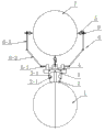
Fig. 1 is the structural representation of the utility model parallelism measuring apparatus;
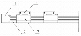
Fig. 2 is slide rail, sliding block and the schematic side view for measuring seat in Fig. 1;
Fig. 3 is the schematic perspective view of measurement seat in Fig. 1.
In figure:1st, reference axis;2nd, slide rail;2-1, V-shaped groove;3rd, sliding block;3-1, projection;4th, seat is measured;5th, measurement table;6th, arm is measured;6-1, horizontal segment;6-2, be inclined upwardly section;6-3, vertical section;7th, shaft forgings or straight-bar;8th, magnet coil;9th, sleeve.
Embodiment
With reference to the accompanying drawings and examples, embodiment of the present utility model is further described.Following examples are only used for clearly illustrating the technical solution of the utility model, and protection domain of the present utility model can not be limited with this.
As shown in Figures 1 to 3, the utility model is a kind of parallelism measuring apparatus, and the measurement apparatus includes the slide rail 2 being arranged on reference axis 1, sliding block 3 is provided with slide rail.Provided with measurement seat 4 on sliding block 3, provided with measurement table 5 and/or by measuring the measurement table 5 that arm 6 is set on measurement seat 4, the measurement table 5 is used to measure beats parallel to the shaft forgings of reference axis 1 or the depth of parallelism, linearity and/or the circle of straight-bar 7.
Preferred embodiment is in the utility model, the top and bottom of slide rail 2 are parallel and lie in a horizontal plane on reference axis 1, V-shaped groove 2-1 is provided with the both sides of slide rail 2, magnet coil 8 is provided with the end of slide rail 2, after magnet coil 8 is powered, sliding block 3 is fixed on slide rail 2 in the presence of electromagnetic force, after magnet coil 8 is powered off, sliding block 3 can be slided along slide rail 2.
Further preferred embodiment is in the utility model, and the upper surface of sliding block 3 is horizontal plane, the projection 3-1 being adapted with V-shaped groove 2-1 is provided with the both sides of sliding block 3, described sliding block 3 has 2 pieces.
Further preferred embodiment also has in the utility model, the measurement seat 4 is the E shape blocks of opening upwards, measurement seat 4 is connected with sliding block 3 by fastener, measurement table 5 is fitted with the middle part of E shapes block measurement seat 4 upper end, the both sides for measuring seat 4 in E shapes block are connected to measurement arm 6, and measurement table 5 is fitted with the end of measurement arm.
Further preferred embodiment also has in the utility model, two measurement arms 6 positioned at measurement seat 4 both sides are located on same vertical plane, measuring arm 6 includes horizontal segment 6-1, be inclined upwardly section 6-2 and vertical section 6-3, horizontal segment 6-1 one end is plugged on the side of measurement seat 6, be inclined upwardly section 6-2 two ends are hinged with the horizontal segment 6- other end and vertical section 6-3 one end respectively, the measurement table 5 positioned at measured piece both sides can be removed by connects hinge when in use, after band workpiece is placed steadily, measurement table 5 is debugged to the position for needing to measure again, test can remove measurement table 5 after terminating secondary, it is so both flexible, it is easy to measurement accurate again.
Further preferred embodiment also has in the utility model, measurement table 5 is inserted into by sleeve 9 on the vertical section 6-3 of measurement arm 6, the measurement table mounting hole perpendicular with the axial direction of sleeve 9 is provided with the side of sleeve 9, screw is additionally provided with the side wall of sleeve 9, in the screw built with the bolt for locking sleeve.
Further preferred embodiment also has in the utility model, and described measurement table 5 is amesdial, and described amesdial can be digital display dial gauge.
The above is only preferred embodiment of the present utility model; it should be understood that; for those skilled in the art; on the premise of the utility model know-why is not departed from; some improvements and modifications can also be made, these improvements and modifications also should be regarded as protection domain of the present utility model.
Claims (8)
1. a kind of parallelism measuring apparatus, it is characterized in that, the measurement apparatus includes the slide rail being arranged on reference axis, sliding block is provided with the slide rail, provided with measurement seat on the sliding block, provided with measurement table and/or by measuring the measurement table that arm is set on the measurement seat, the measurement table is used to measure beats parallel to the shaft forgings of reference axis or the depth of parallelism, linearity and/or the circle of straight-bar.
2. the parallelism measuring apparatus as described in claim l, it is characterised in that the top and bottom of the slide rail are parallel and lie in a horizontal plane on reference axis, V-shaped groove is provided with the both sides of the slide rail, magnet coil is provided with the end of the slide rail.
3. parallelism measuring apparatus as claimed in claim 2, it is characterised in that the upper surface of the sliding block is horizontal plane, and the projection being adapted with the V-shaped groove is provided with the both sides of the sliding block, and described sliding block has 1 ~ 2 piece.
4. parallelism measuring apparatus as claimed in claim 3, it is characterized in that, the measurement seat is the E shape blocks of opening upwards, the measurement seat is connected with sliding block by fastener, measurement table is fitted with the middle part of E shapes block measurement seat upper end, the both sides for measuring seat in the E shapes block are connected to measurement arm, and measurement table is fitted with the end of the measurement arm.
5. parallelism measuring apparatus as claimed in claim 4, it is characterized in that, two measurement arms for being located at measurement seat both sides are located on same vertical plane, the measurement arm includes horizontal segment, the section that is inclined upwardly and vertical section, one end of the horizontal segment is plugged on the side of measurement seat, and the two ends of the section that is inclined upwardly are hinged with the other end of horizontal segment and one end of vertical section respectively.
6. parallelism measuring apparatus as claimed in claim 5, it is characterized in that, the measurement table is inserted into by sleeve on the vertical section of measurement arm, the measurement table mounting hole perpendicular with the axial direction of sleeve is provided with the side of the sleeve, screw is additionally provided with the side wall of the sleeve, in the screw built with the bolt for locking sleeve.
7. the parallelism measuring apparatus as described in claim 1 to 6 any one, it is characterised in that described measurement table is amesdial.
8. parallelism measuring apparatus as claimed in claim 7, it is characterised in that described amesdial is digital display dial gauge.
Priority Applications (1)
| Application Number | Priority Date | Filing Date | Title |
|---|---|---|---|
| CN 201220405584 CN202770380U (en) | 2012-08-16 | 2012-08-16 | Parallelism measuring apparatus |
Applications Claiming Priority (1)
| Application Number | Priority Date | Filing Date | Title |
|---|---|---|---|
| CN 201220405584 CN202770380U (en) | 2012-08-16 | 2012-08-16 | Parallelism measuring apparatus |
Publications (1)
| Publication Number | Publication Date |
|---|---|
| CN202770380U true CN202770380U (en) | 2013-03-06 |
Family
ID=47776946
Family Applications (1)
| Application Number | Title | Priority Date | Filing Date |
|---|---|---|---|
| CN 201220405584 Expired - Fee Related CN202770380U (en) | 2012-08-16 | 2012-08-16 | Parallelism measuring apparatus |
Country Status (1)
| Country | Link |
|---|---|
| CN (1) | CN202770380U (en) |
Cited By (3)
| Publication number | Priority date | Publication date | Assignee | Title |
|---|---|---|---|---|
| CN103954211A (en) * | 2014-05-15 | 2014-07-30 | 中国工程物理研究院机械制造工艺研究所 | Device for measuring parallelism of buses with two rotary bodies |
| CN105806188A (en) * | 2016-04-29 | 2016-07-27 | 北京中丽制机工程技术有限公司 | Suspended shaft parallelism detection device and method |
| CN110440675A (en) * | 2019-07-22 | 2019-11-12 | 北京中航智科技有限公司 | Belt wheel parallelism detecting device |
-
2012
- 2012-08-16 CN CN 201220405584 patent/CN202770380U/en not_active Expired - Fee Related
Cited By (5)
| Publication number | Priority date | Publication date | Assignee | Title |
|---|---|---|---|---|
| CN103954211A (en) * | 2014-05-15 | 2014-07-30 | 中国工程物理研究院机械制造工艺研究所 | Device for measuring parallelism of buses with two rotary bodies |
| CN103954211B (en) * | 2014-05-15 | 2016-06-01 | 中国工程物理研究院机械制造工艺研究所 | A kind of two solid of revolution bus parallelism measuring apparatus |
| CN105806188A (en) * | 2016-04-29 | 2016-07-27 | 北京中丽制机工程技术有限公司 | Suspended shaft parallelism detection device and method |
| CN105806188B (en) * | 2016-04-29 | 2019-05-31 | 北京中丽制机工程技术有限公司 | A kind of hanging axis parallelism detecting device and method |
| CN110440675A (en) * | 2019-07-22 | 2019-11-12 | 北京中航智科技有限公司 | Belt wheel parallelism detecting device |
Similar Documents
| Publication | Publication Date | Title |
|---|---|---|
| CN202195778U (en) | Special check fixture used for measuring position of exhaust pipe hole of automobile | |
| CN203364737U (en) | An apparatus for measuring the circularity of the inner/outer surface of a large/medium-sized bearing ring | |
| CN201688812U (en) | Tooling for measuring depth of groove in hole | |
| CN204788122U (en) | Centering inspection device | |
| CN202770380U (en) | Parallelism measuring apparatus | |
| CN203672284U (en) | Special gauge for measuring length bar distance of annular gear | |
| CN202361923U (en) | External diameter continuous measuring instrument | |
| CN204514256U (en) | The right alignment of hollow tubular workpiece and the measuring equipment of its circularity | |
| CN202770349U (en) | Form and position tolerance measurement device | |
| CN205262386U (en) | Geometric tolerances examines utensil | |
| CN201800391U (en) | Ruler type compasses | |
| CN203591248U (en) | Vision testing box with adjustable support | |
| CN202692910U (en) | Groove depth measuring instrument | |
| CN105021114A (en) | Guide rail parallelism degree simple detecting tool | |
| CN201535661U (en) | Special gauge for gauging engine cylinder hole perpendicularity | |
| CN205014927U (en) | Wall thickness measuring tool | |
| CN203881267U (en) | Go/non-go gauge for interior decorative part production | |
| CN204438994U (en) | A kind of electrical contact eccentric measuring set | |
| CN203605849U (en) | Piston comprehensive test tool | |
| CN201442456U (en) | Plotter | |
| CN203364684U (en) | Steel-plate bending-angle measurement scale | |
| CN203231728U (en) | Multidirectional right angle rapid measuring device | |
| CN203266016U (en) | Handrail welding fixture | |
| CN205079696U (en) | Utensil is examined to portable multistation | |
| CN204478981U (en) | The measurement mechanism that zipper assembling is wide |
Legal Events
| Date | Code | Title | Description |
|---|---|---|---|
| C14 | Grant of patent or utility model | ||
| GR01 | Patent grant | ||
| CF01 | Termination of patent right due to non-payment of annual fee |
Granted publication date: 20130306 Termination date: 20170816 |
|
| CF01 | Termination of patent right due to non-payment of annual fee |