CN202705614U - Automatic doffing machine - Google Patents
Automatic doffing machine Download PDFInfo
- Publication number
- CN202705614U CN202705614U CN 201220305626 CN201220305626U CN202705614U CN 202705614 U CN202705614 U CN 202705614U CN 201220305626 CN201220305626 CN 201220305626 CN 201220305626 U CN201220305626 U CN 201220305626U CN 202705614 U CN202705614 U CN 202705614U
- Authority
- CN
- China
- Prior art keywords
- conveyer belt
- automatic doffer
- drive roll
- groove
- roller frame
- Prior art date
- Legal status (The legal status is an assumption and is not a legal conclusion. Google has not performed a legal analysis and makes no representation as to the accuracy of the status listed.)
- Expired - Lifetime
Links
Images


Abstract
The utility model discloses an automatic doffing machine, which comprises a plurality of yarn releasing devices, a conveying belt, a driving roller, a driven roller and a driving device, wherein the plurality of yarn releasing devices are assembled corresponding to a plurality of winding spindles which are arranged side by side; the conveying belt is arranged below the plurality of winding spindles; the driving roller and the driven roller are positioned on the outer sides of the winding spindles at the two ends which face away from other winding spindles; the conveying belt is sleeved on the driving roller and the driven roller; the driving roller is connected with the driving device; and the driving device can be used for driving the driving roller to rotate. In the automatic doffing machine, the conveying belt is arranged below the winding spindles, and is sleeved on the driving roller and the driven roller. The rotation of the driving roller under the driving action of the driving device can be used for driving the conveying belt to transmit. Spindles falling from the yarn releasing devices fall onto the conveying belt, and move along under the driving action of the conveying belt for conveying.
Description
Technical field
The utility model relates to field of textiles, particularly relates to the automatic doffer for the automatic folding yarn.
Background technology
In this traditional industry of weaving, also have a lot of employings manually to carry out the operation of operation.Such as being to adopt the artificial yarns of receiving after doffing at loose yarn machine, this mode needs operating personnel to cooperate the speed of production of machine, thereby the production efficiency of machine is subjected to operator's effectiveness affects.And the operator is easily tired, finally will cause production efficiency low.
The utility model content
Based on this, be necessary to provide a kind of automatic doffer that can receive yarn, enhance productivity.
A kind of automatic doffer, the a plurality of yarn feeding devices of putting that comprise assembling corresponding to a plurality of coiling spindles that are arranged side by side, be arranged at the conveyer belt of a plurality of coiling spindles below, drive roll, the coiling spindle that driven voller and drive unit, described drive roll and described driven voller lay respectively at two ends is the outside of other coiling spindles dorsad, and described conveyer belt is sheathed on described drive roll and the described driven voller, described drive roll links to each other with described drive unit, and described drive unit can drive described drive roll and rotate.
Therein among embodiment, described drive roll and described driven voller are divided into upper conveyor belt and lower conveyer belt with described conveyer belt, be provided with row's upper supporting roller and row's snub pulley between described drive roll and the described driven voller, described upper supporting roller is positioned at the below of described upper conveyor belt, and all contact with described upper conveyor belt, described snub pulley is positioned at the below of described lower conveyer belt, and all contacts with described lower conveyer belt.
Among embodiment, described automatic doffer also comprises carrier roller frame and carrier roller frame holder therein, and described carrier roller frame is fixed on the carrier roller frame holder, and described upper supporting roller and snub pulley all are fixed in the carrier roller frame.
Among embodiment, be provided with a plurality of draw-in grooves on the described carrier roller frame therein, described upper supporting roller and snub pulley all are fixed on the described carrier roller frame by described draw-in groove.
Therein among embodiment, also be provided with two reversing rollers between the snub pulley of the most close described drive roll in the described snub pulley and the described drive roll, between two described reversing rollers on the lower the position also be provided with jockey pulley, described conveyer belt is between two described reversing rollers, and also on the sheathed and described jockey pulley.
Among embodiment, described automatic doffer also comprises tension adjusting seat therein, and described jockey pulley is arranged on the described tension adjusting seat.
Among embodiment, described automatic doffer also comprises the groove that doffs therein, and the described groove that doffs is positioned at a dorsad side of described driven voller of described drive roll, and described groove and the described conveyer belt of doffing connects.
Among embodiment, the described groove that doffs comprises linkage section and yarn section therein, and described linkage section is positioned on the bearing of trend of described conveyer belt, and described yarn section links to each other with described linkage section, and the bearing of trend of its bearing of trend and described conveyer belt has angle.
Among embodiment, described automatic doffer also comprises robot scaler therein, and described robot scaler is arranged on the described groove that doffs.
Among embodiment, described drive unit is drive motor therein.
Above-mentioned automatic doffer arranges conveyer belt below the coiling spindle, conveyer belt is sheathed on drive roll and the driven voller.The rotation of drive roll can drive described conveyer belt transmission under the driving of drive unit.Just just drop on the conveyer belt from putting the spindle that yarn feeding device falls, the spindle accompany movement is carried under the drive of conveyer belt.
The setting of upper supporting roller and snub pulley can make the conveyer belt smooth running, and resistance and noise are little in running, and transmission efficiency is high.
Carrier roller frame is used for fixing and supports upper supporting roller and snub pulley.
The setting of draw-in groove so that described upper supporting roller and snub pulley all are fixed on the described carrier roller frame by described draw-in groove, is easy to install and maintain.
Also be provided with two reversing rollers between the drive roll, between two described reversing rollers on the lower the position also be provided with jockey pulley, by the upper-lower position of adjustment of tonicity roller, thereby make conveyer belt produce certain tension force.This tension-adjusting gear both can monolateral adjusting belt tension (adjusting like this belt deviation), again can jockey pulley both sides adjusted in concert belt tension.This mode is of value to the operation adjustment of equipment.
Tension adjusting seat is used for the tightness of adjustment of tonicity roller, adjusts at any time the conveying belt tension degree according to the actual needs of producing in the course of the work.
The groove that doffs is used for collecting, and the described groove that doffs is positioned at a dorsad side of described driven voller of described drive roll, and the described groove that doffs is relative with described conveyer belt.Spindle on the conveyer belt can fall into the groove that doffs by nature, in order to the collection of spindle.
Robot scaler is arranged on the described groove that doffs.Robot scaler is used for calculating the concrete number that doffs.
Description of drawings
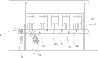
Fig. 1 is the structural representation of automatic doffer described in the utility model;
Fig. 2 is another structural representation of automatic doffer described in the utility model:
Fig. 3 is the structural representation of the groove that doffs of automatic doffer described in the utility model;
Description of reference numerals:
10, put yarn feeding device, 11, draw-in groove, 20, conveyer belt, 21, drive roll, 201, upper conveyor belt, 202, lower conveyer belt, 22, upper supporting roller, 23, snub pulley, 24, the carrier roller frame holder, 25, carrier roller frame, 26, reversing roller, 27, jockey pulley, 28, tension adjusting seat, 30, drive unit, 40, groove doffs, 41, linkage section, 42, the yarn section, 50, robot scaler.
The specific embodiment
Below in conjunction with accompanying drawing embodiment of the present utility model is described further.
See also Fig. 1 and Fig. 2, automatic doffer comprises a plurality of yarn feeding devices 10 of putting of assembling corresponding to a plurality of coiling spindles that are arranged side by side, and is arranged at conveyer belt 20, drive roll 21, driven voller (not shown) and the drive unit 30 of a plurality of coiling spindles below.The coiling spindle that drive roll 21 and driven voller lay respectively at two ends is the outside of other coiling spindles dorsad.Conveyer belt 20 is sheathed on drive roll 21 and the driven voller.Drive roll 21 links to each other with drive unit 30, and drive unit 30 is used for driving drive roll 21 and rotates.In the present embodiment, drive unit 30 is drive motor.
Automatic doffer also comprises carrier roller frame 25, and carrier roller frame 25 is fixed on the carrier roller frame holder, and upper supporting roller 22 and snub pulley 23 all are fixed in the draw-in groove on the carrier roller frame 25.
Be provided with a plurality of draw-in grooves 11 on the carrier roller frame 25, upper supporting roller 22 and snub pulley 23 all are fixed on the carrier roller frame 25 by draw-in groove 11.
Also being provided with between 26, two reversing rollers 26 of two reversing rollers on the lower between the snub pulley 23 of the most close drive roll 21 in the snub pulley 23 and the drive roll 21, the position also is provided with jockey pulley 27.Conveyer belt 20 is between two reversing rollers 26, and also on sheathed and the jockey pulley 27.
Automatic doffer also comprises tension adjusting seat 28, and jockey pulley 27 is arranged on the tension adjusting seat 28.
Automatic doffer also comprises the groove 40 that doffs, and the groove 40 that doffs is positioned at a dorsad side of driven voller of drive roll 21, and the groove 40 that doffs connects with carrying 20 bands.
See also Fig. 3, the groove 40 that doffs comprises linkage section 41 and yarn section 42, and linkage section 41 is positioned on the bearing of trend of conveyer belt 20, and yarn section 42 links to each other with linkage section 41, and the bearing of trend of its bearing of trend and conveyer belt 20 has angle.
Automatic doffer also comprises robot scaler 50, and robot scaler 50 is arranged on the groove 40 that doffs.
Above-mentioned automatic doffer arranges conveyer belt below the coiling spindle, conveyer belt is sheathed on drive roll and the driven voller.The rotation of drive roll can drive described conveyer belt transmission under the driving of drive unit.Just just drop on the conveyer belt from putting the spindle that yarn feeding device falls, the spindle accompany movement is carried under the drive of conveyer belt.
The setting of upper supporting roller and snub pulley can make the conveyer belt smooth running, and resistance and noise are little in running, and transmission efficiency is high.
Carrier roller frame is used for fixing and supports upper supporting roller and snub pulley.
The setting of draw-in groove so that described upper supporting roller and snub pulley all are fixed on the described carrier roller frame by described draw-in groove, is easy to install and maintain.
Also be provided with two reversing rollers between the drive roll, between two described reversing rollers on the lower the position also be provided with jockey pulley, by the upper-lower position of adjustment of tonicity roller, thereby make conveyer belt produce certain tension force.This tension-adjusting gear both can monolateral adjusting belt tension (adjusting like this belt deviation), again can jockey pulley both sides adjusted in concert belt tension.This mode is of value to the operation adjustment of equipment.
Tension adjusting seat is used for the tightness of adjustment of tonicity roller, adjusts at any time the conveying belt tension degree according to the actual needs of producing in the course of the work.
The groove that doffs is used for collecting, and the described groove that doffs is positioned at a dorsad side of described driven voller of described drive roll, and the described groove that doffs is relative with described conveyer belt.Spindle on the conveyer belt can fall into the groove that doffs by nature, in order to the collection of spindle.
Robot scaler is arranged on the described groove that doffs.Robot scaler is used for calculating the concrete number that doffs.
The above embodiment has only expressed several embodiment of the present utility model, and it describes comparatively concrete and detailed, but can not therefore be interpreted as the restriction to the utility model claim.Should be pointed out that for the person of ordinary skill of the art, without departing from the concept of the premise utility, can also make some distortion and improvement, these all belong to protection domain of the present utility model.Therefore, the protection domain of the utility model patent should be as the criterion with claims.
Claims (10)
1. automatic doffer, it is characterized in that, the a plurality of yarn feeding devices of putting that comprise assembling corresponding to a plurality of coiling spindles that are arranged side by side, be arranged at the conveyer belt of a plurality of coiling spindles below, drive roll, driven voller and drive unit, the coiling spindle that described drive roll and described driven voller lay respectively at two ends is the outside of other coiling spindles dorsad, described conveyer belt is sheathed on described drive roll and the described driven voller, described drive roll links to each other with described drive unit, and described drive unit drives described drive roll and rotates.
2. automatic doffer as claimed in claim 1, it is characterized in that, described drive roll and described driven voller are divided into upper conveyor belt and lower conveyer belt with described conveyer belt, be provided with row's upper supporting roller and row's snub pulley between described drive roll and the described driven voller, described upper supporting roller is positioned at the below of described upper conveyor belt, and all contact with described upper conveyor belt, described snub pulley is positioned at the below of described lower conveyer belt, and all contacts with described lower conveyer belt.
3. automatic doffer as claimed in claim 1 or 2 is characterized in that, described automatic doffer also comprises carrier roller frame and carrier roller frame holder, and described carrier roller frame is fixed on the carrier roller frame holder, and described upper supporting roller and snub pulley all are fixed in the carrier roller frame.
4. automatic doffer as claimed in claim 3 is characterized in that, is provided with a plurality of draw-in grooves on the described carrier roller frame, and described upper supporting roller and snub pulley all are fixed on the described carrier roller frame by described draw-in groove.
5. automatic doffer as claimed in claim 2, it is characterized in that, also be provided with two reversing rollers between the snub pulley of the most close described drive roll in the described snub pulley and the described drive roll, between two described reversing rollers on the lower the position also be provided with jockey pulley, described conveyer belt is between two described reversing rollers, and also on the sheathed and described jockey pulley.
6. automatic doffer as claimed in claim 5 is characterized in that, described automatic doffer also comprises tension adjusting seat, and described jockey pulley is arranged on the described tension adjusting seat.
7. automatic doffer as claimed in claim 1 is characterized in that, described automatic doffer also comprises the groove that doffs, and the described groove that doffs is positioned at a dorsad side of described driven voller of described drive roll, and described groove and the described conveyer belt of doffing connects.
8. automatic doffer as claimed in claim 7, it is characterized in that, the described groove that doffs comprises linkage section and yarn section, and described linkage section is positioned on the bearing of trend of described conveyer belt, described yarn section links to each other with described linkage section, and the bearing of trend of its bearing of trend and described conveyer belt has angle.
9. automatic doffer as claimed in claim 7 is characterized in that, described automatic doffer also comprises robot scaler, and described robot scaler is arranged on the described groove that doffs.
10. automatic doffer as claimed in claim 1 is characterized in that, described drive unit is drive motor.
Priority Applications (1)
| Application Number | Priority Date | Filing Date | Title |
|---|---|---|---|
| CN 201220305626 CN202705614U (en) | 2012-06-27 | 2012-06-27 | Automatic doffing machine |
Applications Claiming Priority (1)
| Application Number | Priority Date | Filing Date | Title |
|---|---|---|---|
| CN 201220305626 CN202705614U (en) | 2012-06-27 | 2012-06-27 | Automatic doffing machine |
Publications (1)
| Publication Number | Publication Date |
|---|---|
| CN202705614U true CN202705614U (en) | 2013-01-30 |
Family
ID=47585935
Family Applications (1)
| Application Number | Title | Priority Date | Filing Date |
|---|---|---|---|
| CN 201220305626 Expired - Lifetime CN202705614U (en) | 2012-06-27 | 2012-06-27 | Automatic doffing machine |
Country Status (1)
| Country | Link |
|---|---|
| CN (1) | CN202705614U (en) |
Cited By (1)
| Publication number | Priority date | Publication date | Assignee | Title |
|---|---|---|---|---|
| CN102719947A (en) * | 2012-06-27 | 2012-10-10 | 广东溢达纺织有限公司 | Automatic doffing machine |
-
2012
- 2012-06-27 CN CN 201220305626 patent/CN202705614U/en not_active Expired - Lifetime
Cited By (1)
| Publication number | Priority date | Publication date | Assignee | Title |
|---|---|---|---|---|
| CN102719947A (en) * | 2012-06-27 | 2012-10-10 | 广东溢达纺织有限公司 | Automatic doffing machine |
Similar Documents
| Publication | Publication Date | Title |
|---|---|---|
| CN211569694U (en) | Conveyer is used in production of spandex yarn | |
| CN109554840B (en) | Dense mesh type safety net production equipment | |
| CN107444981A (en) | A kind of weaving winding device | |
| CN202705614U (en) | Automatic doffing machine | |
| CN211034662U (en) | Yarn conveying device for textile machinery | |
| CN204898186U (en) | Single spindle list accuse twisting frame | |
| CN109112672B (en) | Continuous wool top bracing device | |
| CN104153056A (en) | Automatic discharging coiling machine | |
| CN210162924U (en) | Wool top conveying and winding device | |
| CN204039594U (en) | A kind of spun yarn device | |
| CN203049132U (en) | Spindle transmission mechanism of twisting machine | |
| CN208916468U (en) | A kind of novel hard waste machine | |
| CN102719947A (en) | Automatic doffing machine | |
| CN210215701U (en) | Warping machine | |
| CN202509185U (en) | Improved individual cotton cutting device for drawing frame | |
| CN212834225U (en) | Double-roller single-spindle single-control twisting machine | |
| CN210823983U (en) | Special transfer chain of spandex silk | |
| CN109457341B (en) | Spindle driving mechanism on yarn covering machine | |
| CN208790904U (en) | A kind of three line doubling frames | |
| CN202575537U (en) | Traversing mechanism of chemical fiber two-for-one twister | |
| CN107130318A (en) | A kind of both-end arm fixes the high rack device of suspension type | |
| CN207159452U (en) | A kind of both-end arm fixes the high rack device of suspension type | |
| CN206529568U (en) | A kind of textile production removes device with air pressure | |
| CN203270129U (en) | Device for enabling upper layer web and lower layer web of FA360 sliver lap machine to synchronously run | |
| CN201495341U (en) | Novel conveying device for rotor spinner |
Legal Events
| Date | Code | Title | Description |
|---|---|---|---|
| C14 | Grant of patent or utility model | ||
| GR01 | Patent grant | ||
| CX01 | Expiry of patent term |
Granted publication date: 20130130 |
|
| CX01 | Expiry of patent term |