The automatic collator of shell
Technical field
The utility model is mainly used in explosive and makes field, the automatic collator of particularly a kind of shell class.
Background technology
At present, the automatic collator of domestic shell all is semi-automatic half artificial mode of operation, and after collator sorted shell, the working process of mould, peel of mould was transported in manual work.There are shortcomings such as the work situation is complicated, kind is single and the safe staffing of very difficult minimizing, and labour intensity is big in this kind mode.
Summary of the invention
The purpose of the utility model is to provide a kind of shell automatic collator, solved that present technology exists make the situation complicacy, problem such as kind is single and the safe staffing of very difficult minimizing, and labour intensity is big.The utility model automatic tube-arranging, automatically send mould, mould separates automatically up and down, can adapt to various shells.This has played in production line and important effect.This equipment is operated with man-machine interface, has characteristics such as simple to operate, directly perceived, safe in utilization, reliable, reduction labour intensity.Realized that shell sorts automatically, omitted pipe in printing and detect, mould transmission, function such as mold separation up and down.
The above-mentioned purpose of the utility model realizes through following technical scheme:
The automatic collator of shell comprises the shell transfer device, omits tube detection device in printing, feed bin, rolling body group and PWR PLT that table top 2 is connected with support body 1; Said shell transfer device comprises back up pad 3, right baffle-plate 4, turnover stool 5, rib I 6, matched moulds plate 7, right baffle plate 8, cylinder support I 9, lip block I 21, pushing block II 27, divides mould cutter 28, cushion block I 29, cushion block II 30, cylinder support III 31, slideway 34, cylinder support II 40, lip block II 41, rib 42, short slideway 43 and two cylinders; Said back up pad 3, right baffle-plate 4, right baffle plate 8, cylinder support I 9, lip block I 21, cylinder support III 31, cylinder support II 40, lip block II 41, rib 42, slideway 34, short slideway 43 are connected with table top 2 respectively; Said turnover stool 5 is connected with back up pad 3; Rib I 6 is connected with turnover stool 5; Matched moulds plate 7 is connected with cylinder; Cylinder is connected with table top 2, and cylinder support I 9 is connected with table top 2, cylinder support II 40 is connected with left and right baffle plate 4,8 respectively; Said pushing block II 27 is connected with cylinder, divides mould cutter 28 function ribs 42 to connect, and cushion block I 29, cushion block II 30 are connected with table top 2 respectively.The process of having transmitted behind mould matched moulds and the branch mould about the shell transfer device has been realized.To divide the connection of mould and shell transfer device be one of difficult point of whole equipment, also can not realize this function in the tube drawbench at home.
The said tube detection device of omitting in printing comprises check-out console 10, guide pin bushing 11, guide pillar 12, gib block 37, cylinder connection box 38, bearing plate 39 and cylinder; Said gib block 37 is connected with bearing plate 39; Bearing plate 39 is connected with table top 2; Connection box 38 is connected with bearing plate 39, and check-out console 10 is connected with cylinder, and guide pin bushing 11, guide pillar 12 are connected with cylinder connection box (38) respectively.Through omitting tube detection device in printing can know and omitted how many shells in printing omitted in printing in which position of mould.
Said feed bin is made up of combo box 13, mobile 14 and base plate 15, and feed bin is connected with chock I 16, and mobile 14 works to stop that shell jumps to the full mould place of row in the process of comb shell.
Said rolling body group comprises chock I 16, running roller 17, the axis of guide 18, axis of guide axle bed 19, support 35, pinch roller 36, end cap 45, axle sleeve 46, little axle 47, axial back-up ring and bearing; Said chock I 16, running roller 17, axle sleeve 46, little axle 47, bearing, circlip for shaft interconnect; Running roller 17 links to each other with the axis of guide 18; The axis of guide 18 is connected with axis of guide axle bed 19, and guiding axle bed 19, support 35 are connected with table top 2 respectively, and pinch roller 36 is connected with support 35.The utility model has 4 rolling bodys; In the process of feed bin vibrations, played effect steady and guiding; It has played very big effect in whole equipment; Can the shell success of sorting mainly see the frequency of vibration and the stability of vibration, and the stability of vibration depends on the motion stabilization of 4 rolling bodys.
Said PWR PLT comprise erecting frame 23, chock II 24, excentric shaft 25, bar linkage structure 26, bearing, belt wheel, wire belt, step-down gear and motor; Said erecting frame 23 is connected with base plate 15, and linkage assembly 26 is connected with excentric shaft 25 and erecting frame 23 respectively, and excentric shaft 25 is connected with chock II 24; Chock II 24 is connected with table top 2; Wire belt, belt wheel, step-down gear are connected with support body 1 with excentric shaft respectively, and step-down gear links to each other with motor through shaft coupling, and motor is connected with support body 1.Drive blanking bin vibration carrying out comb shell at motor.
Bed die 22 is set in the said feed bin; Said bed die 22 comprises that steady brace 221, stiffening plate 222, spring 223, bed die guide pillar 224, bed die accept post 225, bed die base plate 226, bed die pressing plate 227, bed die upper plate 228 and rubber pad 229; Said steady brace 221 is installed in the bed die base plate 226; Bed die guide pillar 224 is connected with bed die upper plate 228, and bed die base plate 226 slides in steady brace 221; Bed die is accepted post 225 and is cooperated with bed die pressing plate 227, under rubber pad 229 effect, makes bed die accept post 225 perpendicular to backing plate and do not rock; Shell is accepted on the post 225 being buckled in bed die through its chamfering guiding on the bed die upper plate 228, and tube shell bottom can withstand on bed die and accepts on the post 225 when reverse shell, is anchored to bed die after can reversing through the reverse shell of vibration and accepts on the post 225.Said steady brace 221 installs stiffening plate 222 additional with bed die base plate 226 stage, prevents in use to reduce owing to the material on floor 226 work-ing life of entire die.One end mounting spring 223 of bed die guide pillar 224, under the reactive force of spring 223, the upper plate 228 maintenance levels that make guide pillar 224 connections.
Cylinder support 20 is connected with table top with cylinder respectively, and cylinder is released mold outside the automatic collator of shell.Pushing block I 30, pushing block III 32, cushion block III 33, rib 44 are connected with table top 2 with the difference cylinder, under two cylinder actions, accomplish bed die and are transferred to automatic collator place.Pushing block IV 29 is connected the action of accomplishing the bed die feeding warehouse with cylinder.
When the utility model uses in reality; Artificial shell is placed in the feed bin, start automatic sequencing procedure → shell to be ordered into automatically in the bed die → mould transmission path startups → bed die is transferred to proofing unit place → proofing unit decline → detection and whether omits shell → proofing unit rising → mould transmission path in printing and transmit bed die to shell transfer device place → shell transfer device rising → shell and be delivered in the mold → mold is transferred to outside the automatic collator of shell → bed die is transferred to automatic collator place.The automatic ordering action of shell has just been accomplished in this a series of action.
The beneficial effect of the utility model is: novel structure, simple, easy to use.Employing is operated with man-machine interface, has characteristics such as simple to operate, directly perceived, safe in utilization, reliable, reduction labour intensity.Realized that shell sorts automatically, omitted pipe in printing and detect, the mould transmission, function such as mold separation is practical up and down.
Description of drawings
Accompanying drawing described herein is used to provide the further understanding to the utility model, constitutes the application's a part, and illustrative example of the utility model and explanation thereof are used to explain the utility model, do not constitute the improper qualification to the utility model.
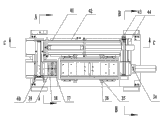
Fig. 1 is the main TV structure synoptic diagram of the utility model;
Fig. 2 is the D-D cross-sectional schematic of Fig. 1;
Fig. 3 is the schematic top plan view of the utility model;
Fig. 4 is the A-A cross-sectional schematic of Fig. 3;
Fig. 5 is the B-B cross-sectional schematic of Fig. 3;
Fig. 6 is the C-C cross-sectional schematic of Fig. 3;
Fig. 7 is the E-E cross-sectional schematic of Fig. 3;
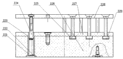
Fig. 8 is the structural representation of the bed die of the utility model.
Embodiment
Further specify the detailed content and the embodiment thereof of the utility model below in conjunction with accompanying drawing.
Referring to Fig. 1 to Fig. 7, the automatic collator of the shell of the utility model comprises the shell transfer device, omits tube detection device in printing, feed bin, rolling body group and PWR PLT that table top 2 is connected with support body 1; Said shell transfer device comprises back up pad 3, right baffle-plate 4, turnover stool 5, rib I 6, matched moulds plate 7, right baffle plate 8, cylinder support I 9, lip block I 21, pushing block II 27, divides mould cutter 28, cushion block I 29, cushion block II 30, cylinder support III 31, slideway 34, cylinder support II 40, lip block II 41, rib 42, short slideway 43 and two cylinders; Said back up pad 3, right baffle-plate 4, right baffle plate 8, cylinder support I 9, lip block I 21, cylinder support III 31, cylinder support II 40, lip block II 41, rib 42, slideway 34, short slideway 43 are connected with table top 2 respectively; Said turnover stool 5 is connected with back up pad 3; Rib I 6 is connected with turnover stool 5; Matched moulds plate 7 is connected with cylinder; Cylinder is connected with table top 2, and cylinder support I 9 is connected with table top 2, cylinder support II 40 is connected with left and right baffle plate 4,8 respectively; Said pushing block II 27 is connected with cylinder, divides mould cutter 28 function ribs 42 to connect, and cushion block I 29, cushion block II 30 are connected with table top 2 respectively.The process of having transmitted behind mould matched moulds and the branch mould about the shell transfer device has been realized.To divide the connection of mould and shell transfer device be one of difficult point of whole equipment, also can not realize this function in the tube drawbench at home.
The said tube detection device of omitting in printing comprises check-out console 10, guide pin bushing 11, guide pillar 12, gib block 37, cylinder connection box 38, bearing plate 39 and cylinder; Said gib block 37 is connected with bearing plate 39; Bearing plate 39 is connected with table top 2; Connection box 38 is connected with bearing plate 39, and check-out console 10 is connected with cylinder, and guide pin bushing 11, guide pillar 12 are connected with cylinder connection box (38) respectively.Through omitting tube detection device in printing can know and omitted how many shells in printing omitted in printing in which position of mould.
Said feed bin is made up of combo box 13, mobile 14 and base plate 15, and feed bin is connected with chock I 16, and mobile 14 works to stop that shell jumps to the full mould place of row in the process of comb shell.
Said rolling body group comprises chock I 16, running roller 17, the axis of guide 18, axis of guide axle bed 19, support 35, pinch roller 36, end cap 45, axle sleeve 46, little axle 47, axial back-up ring and bearing; Said chock I 16, running roller 17, axle sleeve 46, little axle 47, bearing, circlip for shaft interconnect; Running roller 17 links to each other with the axis of guide 18; The axis of guide 18 is connected with axis of guide axle bed 19, and guiding axle bed 19, support 35 are connected with table top 2 respectively, and pinch roller 36 is connected with support 35.The utility model has 4 rolling bodys; In the process of feed bin vibrations, played effect steady and guiding; It has played very big effect in whole equipment; Can the shell success of sorting mainly see the frequency of vibration and the stability of vibration, and the stability of vibration depends on the motion stabilization of 4 rolling bodys.
Said PWR PLT comprise erecting frame 23, chock II 24, excentric shaft 25, bar linkage structure 26, bearing, belt wheel, wire belt, step-down gear and motor; Said erecting frame 23 is connected with base plate 15, and linkage assembly 26 is connected with excentric shaft 25 and erecting frame 23 respectively, and excentric shaft 25 is connected with chock II 24; Chock II 24 is connected with table top 2; Wire belt, belt wheel, step-down gear are connected with support body 1 with excentric shaft respectively, and step-down gear links to each other with motor through shaft coupling, and motor is connected with support body 1.Drive blanking bin vibration carrying out comb shell at motor.
Referring to Fig. 8; Bed die 22 is set in the said feed bin; Said bed die 22 comprises that steady brace 221, stiffening plate 222, spring 223, bed die guide pillar 224, bed die accept post 225, bed die base plate 226, bed die pressing plate 227, bed die upper plate 228 and rubber pad 229; Said steady brace 221 is installed in the bed die base plate 226, and bed die guide pillar 224 is connected with bed die upper plate 228, and bed die base plate 226 slides in steady brace 221; Bed die is accepted post 225 and is cooperated with bed die pressing plate 227, under rubber pad 229 effect, makes bed die accept post 225 perpendicular to backing plate and do not rock; Shell is accepted on the post 225 being buckled in bed die through its chamfering guiding on the bed die upper plate 228, and tube shell bottom can withstand on bed die and accepts on the post 225 when reverse shell, is anchored to bed die after can reversing through the reverse shell of vibration and accepts on the post 225.Said steady brace 221 installs stiffening plate 222 additional with bed die base plate 226 stage, prevents in use to reduce owing to the material on floor 226 work-ing life of entire die.One end mounting spring 223 of bed die guide pillar 224, under the reactive force of spring 223, the upper plate 228 maintenance levels that make guide pillar 224 connections.
Cylinder support 20 is connected with table top with cylinder respectively, and cylinder is released mold outside the automatic collator of shell.Pushing block I 30, pushing block III 32, cushion block III 33, rib 44 are connected with table top 2 with the difference cylinder, under two cylinder actions, accomplish bed die and are transferred to automatic collator place.Pushing block IV 29 is connected the action of accomplishing the bed die feeding warehouse with cylinder.
The preferred embodiment that the above is merely the utility model is not limited to the utility model, and for a person skilled in the art, the utility model can have various changes and variation.All within the spirit and principle of the utility model, any modification of being done, be equal to replacement, improvement etc., all should be included within the protection domain of the utility model.