CN202491908U - Lock device applied to emergency cabin covering cap and emergency cabin covering cap including the same - Google Patents
Lock device applied to emergency cabin covering cap and emergency cabin covering cap including the same Download PDFInfo
- Publication number
- CN202491908U CN202491908U CN 201220052989 CN201220052989U CN202491908U CN 202491908 U CN202491908 U CN 202491908U CN 201220052989 CN201220052989 CN 201220052989 CN 201220052989 U CN201220052989 U CN 201220052989U CN 202491908 U CN202491908 U CN 202491908U
- Authority
- CN
- China
- Prior art keywords
- cover plate
- linkage
- sleeve pipe
- locking device
- distance
- Prior art date
- Legal status (The legal status is an assumption and is not a legal conclusion. Google has not performed a legal analysis and makes no representation as to the accuracy of the status listed.)
- Expired - Fee Related
Links
- 238000009434 installation Methods 0.000 claims abstract description 33
- 210000005056 cell body Anatomy 0.000 claims 8
- 238000010586 diagram Methods 0.000 description 5
- 238000000034 method Methods 0.000 description 2
- 101150106235 ISPS gene Proteins 0.000 description 1
- 230000009286 beneficial effect Effects 0.000 description 1
- 230000000694 effects Effects 0.000 description 1
- 238000003466 welding Methods 0.000 description 1
Images


Landscapes
- Lock And Its Accessories (AREA)
Abstract
本实用新型涉及一种锁装置及包含其的应急舱口盖,应急舱口盖包括盖板,盖板上穿设有安装轴,安装轴上相对盖板的内外两端上均设有手轮,且安装轴上还设置有与盖板具有一第一距离的联动装置,联动装置包括与设置在围板上的限位楔块对应的楔形部,且联动装置具有一使楔形部脱离限位楔块的开启方向,锁装置设置在盖板上且位于一限制联动装置朝开启方向旋转的位置上,锁装置包括套管和插销,套管固定于盖板上,且套管的管壁上具有一栓槽;插销与套管对应,且插销上突出一与栓槽对应的销栓;其中,套管的长度小于第一距离,插销的长度大于第一距离。本实用新型满足了《国际船舶和港口实施保安规则》的要求,且方便、可靠还可满足应急状态下逃生需求。
The utility model relates to a lock device and an emergency hatch cover comprising the same. The emergency hatch cover includes a cover plate, and an installation shaft is pierced on the cover plate, and handwheels are provided on the inner and outer ends of the installation shaft opposite to the cover plate. , and the installation shaft is also provided with a linkage device with a first distance from the cover plate, the linkage device includes a wedge-shaped part corresponding to the limit wedge block arranged on the enclosure plate, and the linkage device has a wedge-shaped part out of the limit In the opening direction of the wedge, the lock device is arranged on the cover plate and is located at a position that restricts the linkage device from rotating in the opening direction. The lock device includes a sleeve and a latch, the sleeve is fixed on the cover plate, and the tube wall of the sleeve There is a bolt groove; the bolt corresponds to the bushing, and a bolt corresponding to the bolt groove protrudes from the bolt; wherein, the length of the bushing is smaller than the first distance, and the length of the bolt is longer than the first distance. The utility model satisfies the requirements of the "International Ship and Port Implementation Security Regulations", and is convenient and reliable, and can also meet the need for escape in an emergency state.
Description
技术领域 technical field
本实用新型涉及一种锁装置,具体地说,是涉及一种用于应急舱口盖的锁装置。本实用新型还涉及一种应急舱口盖。The utility model relates to a lock device, in particular to a lock device used for an emergency hatch cover. The utility model also relates to an emergency hatch cover.
背景技术 Background technique
目前,依据CB/T 3728-1995,CB/T 3846-2000的应急舱口盖结构有如图1所示的结构,包括盖板10,盖板10上穿设有安装轴20,安装轴20上相对盖板10的内外两端上均设有手轮30、30′,且安装轴20上还设置有联动装置40。结合参阅图2(由于现有技术的应急舱口盖结构与本实用新型的应急舱口盖结构大致相同,故在附图中未给出现有技术的应急舱口盖结构图),联动装置40包括本体41、第一联动杆42、第二联动杆43、第三联动杆44、第四联动杆45,本体41套设在安装轴20上,第一联动杆42为多根,均匀分布在本体41的外缘上,每一第一联动杆42的远离本体41的一端上铰接一根第二联动杆43,第二联动杆43的远离第一联动杆42的一端上铰接一根第三联动杆44,每一第三联动杆44的两端分别铰接一根第四联动杆45,且第二联动杆43与第三联动杆44的铰接位置同于第三联动杆44与第四联动杆45的铰接位置,每一第四联动杆45的远离第三联动杆43的一端具有楔形部451,每一楔形部451与一限位楔块60对应,限位楔块60设置在围板50上。通过上述结构,开启盖板10时,通过旋转手轮30或手轮30′带动联动装置40使楔形部451脱离围板50上的限位楔块60,从而打开盖板10,舱室内外的人员可以随便进入。由于该种结构的应急舱口盖,从舱室内外均能进出,不具有防海盗进入的措施。但是,凡是需要满足《国际船舶和港口实施保安规则》(International Shipand Port Facility Security Code简称ISPS规范)PART-A强制要求的船舶,均要求所有的通道点在不用时,需要有效的锁和格栅保护,因此,目前的应急舱口盖不能满足《国际船舶和港口实施保安规则》的要求。At present, according to CB/T 3728-1995, the emergency hatch cover structure of CB/T 3846-2000 has the structure shown in Figure 1, including the
实用新型内容 Utility model content
本实用新型所要解决的技术问题是,提供一种用于应急舱口盖的锁装置,以使应急舱口盖满足《国际船舶和港口实施保安规则》的要求。The technical problem to be solved by the utility model is to provide a lock device for an emergency hatch cover, so that the emergency hatch cover meets the requirements of the "International Ship and Port Security Regulations".
为了实现上述目的,本实用新型的锁装置用于应急舱口盖上,所述应急舱口盖包括盖板,所述盖板上穿设有安装轴,安装轴上相对盖板的内外两端上均设有手轮,且安装轴上还设置有与所述盖板具有一第一距离的联动装置,所述联动装置包括与设置在围板上的限位楔块对应的楔形部,且所述联动装置具有一使所述楔形部脱离所述限位楔块的开启方向,所述锁装置设置在所述盖板上且位于一限制所述联动装置朝所述开启方向旋转的位置上,所述锁装置包括套管和插销,所述套管固定于所述盖板上,且所述套管的管壁上具有一栓槽;所述插销与所述套管对应,且所述插销上突出一与所述栓槽对应的销栓;其中,所述套管的长度小于所述第一距离,所述插销的长度大于所述第一距离。In order to achieve the above object, the lock device of the present utility model is used on the emergency hatch cover, and the emergency hatch cover includes a cover plate, and the cover plate is pierced with an installation shaft, and the inner and outer ends of the cover plate are opposite to each other on the installation shaft. Handwheels are provided on the top, and a linkage device having a first distance from the cover plate is also provided on the installation shaft, and the linkage device includes a wedge corresponding to the limit wedge set on the enclosure plate, and The linkage device has an opening direction for disengaging the wedge-shaped part from the limiting wedge, and the lock device is arranged on the cover plate and is located at a position that restricts the linkage device from rotating in the opening direction , the lock device includes a sleeve and a bolt, the sleeve is fixed on the cover plate, and the wall of the sleeve has a bolt groove; the bolt corresponds to the sleeve, and the A pin corresponding to the pin slot protrudes from the pin; wherein, the length of the sleeve is smaller than the first distance, and the length of the pin is greater than the first distance.
上述的锁装置,其中,所述插销包括销头及销体,所述销栓位于所述销体上,所述销头上具有一安装部。In the aforementioned lock device, wherein the bolt includes a pin head and a pin body, the pin bolt is located on the pin body, and the pin head has a mounting portion.
上述的锁装置,其中,所述销体的长度大于所述第一距离。In the aforementioned lock device, the length of the pin body is greater than the first distance.
上述的锁装置,其中,所述盖板上设置有一挂锁装置,所述挂锁装置的远离所述盖板一端设置在所述安装部上。In the aforementioned lock device, a padlock device is provided on the cover plate, and an end of the padlock device away from the cover plate is provided on the installation portion.
上述的锁装置,其中,所述栓槽包括第一槽体部和第二槽体部,所述第一槽体部沿所述套管的轴向设置,所述第二槽体部沿所述套管的周向设置。The aforementioned lock device, wherein, the bolt groove includes a first groove body part and a second groove body part, the first groove body part is arranged along the axial direction of the sleeve, and the second groove body part is arranged along the The circumferential setting of the casing.
进一步地,本实用新型还提供一种应急舱口盖,所述应急舱口盖包括盖板和锁装置,所述盖板上穿设有安装轴,安装轴上相对盖板的内外两端上均设有手轮,且安装轴上还设置有与所述盖板具有一第一距离的联动装置,所述联动装置包括与设置在围板上的限位楔块对应的楔形部,且所述联动装置具有一使所述楔形部脱离所述限位楔块的开启方向,所述锁装置设置在所述盖板上且位于一限制所述联动装置朝所述开启方向旋转的位置上,所述锁装置包括套管和插销,所述套管固定于所述盖板上,且所述套管的管壁上具有一栓槽;所述插销与所述套管对应,且所述插销上突出一与所述栓槽对应的销栓;其中,所述套管的长度小于所述第一距离,所述插销的长度大于所述第一距离。Further, the utility model also provides an emergency hatch cover, the emergency hatch cover includes a cover plate and a lock device, the cover plate is pierced with an installation shaft, and the inner and outer ends of the installation shaft are opposite to the cover plate. Handwheels are all provided, and a linkage device with a first distance from the cover plate is also provided on the installation shaft. The linkage device has an opening direction for disengaging the wedge-shaped part from the limit wedge, the lock device is arranged on the cover plate and is located at a position that restricts the linkage device from rotating in the opening direction, The lock device includes a bushing and a bolt, the bushing is fixed on the cover plate, and a bolt groove is formed on the wall of the bushing; the bolt corresponds to the bushing, and the bolt A pin corresponding to the pin groove protrudes from the top; wherein, the length of the sleeve is less than the first distance, and the length of the bolt is greater than the first distance.
上述的应急舱口盖,其中,所述插销包括销头及销体,所述销栓位于所述销体上,所述销头上具有一安装部。In the above emergency hatch cover, wherein the bolt includes a pin head and a pin body, the pin bolt is located on the pin body, and the pin head has a mounting portion.
上述的应急舱口盖,其中,所述销体的长度大于所述第一距离。In the above emergency hatch cover, the length of the pin body is greater than the first distance.
上述的应急舱口盖,其中,所述盖板上设置有一挂锁装置,所述挂锁装置的远离所述盖板一端设置在所述安装部上。In the above emergency hatch cover, a padlock device is provided on the cover plate, and an end of the padlock device away from the cover plate is provided on the installation part.
上述的应急舱口盖,其中,所述栓槽包括第一槽体部和第二槽体部,所述第一槽体部沿所述套管的轴向设置,所述第二槽体部沿所述套管的周向设置。The above-mentioned emergency hatch cover, wherein, the bolt groove includes a first groove body part and a second groove body part, the first groove body part is arranged along the axial direction of the casing, and the second groove body part along the circumference of the sleeve.
本实用新型的有益功效在于,通过锁装置的设置,于关闭盖体后、插销插入套管、销栓卡入栓槽时,将限制联动装置的开启方向,外部人员无法打开盖体,从而满足了《国际船舶和港口实施保安规则》的要求,且方便、可靠还可满足应急状态下逃生需求。The beneficial effect of the utility model is that, through the setting of the lock device, when the cover is closed, the bolt is inserted into the casing, and the pin is inserted into the bolt groove, the opening direction of the linkage device will be limited, and the outside personnel cannot open the cover, thereby satisfying the It meets the requirements of the "International Ship and Port Implementation Security Code", and is convenient and reliable, and can also meet the escape needs in emergency situations.
以下结合附图和具体实施例对本实用新型进行详细描述,但不作为对本实用新型的限定。The utility model will be described in detail below in conjunction with the accompanying drawings and specific embodiments, but not as a limitation of the utility model.
附图说明 Description of drawings
图1为本实用新型的应急舱口盖的结构图;Fig. 1 is the structural diagram of the emergency hatch cover of the present utility model;
图2为图1中的B-B剖视图;Fig. 2 is B-B sectional view among Fig. 1;
图3为本实用新型的锁装置的结构图;Fig. 3 is the structural diagram of lock device of the present utility model;
图4为图3中的套管局部图;Fig. 4 is a partial view of the bushing in Fig. 3;
图5为图3中的插销结构图。Fig. 5 is a structural diagram of the latch in Fig. 3 .
其中,附图标记Among them, reference signs
10-盖板10-cover
20-安装轴20-installation shaft
30、30′-手轮30, 30'-hand wheel
40-联动装置40-linkage device
41-本体41-Ontology
42-第一联动杆42-The first linkage rod
43-第二联动杆43-Second linkage rod
44-第三联动杆44-The third linkage rod
45-第四联动杆45-the fourth linkage rod
451-楔形部451-Wedge
50-围板50-coaming
60-限位楔块60-limit wedge
70-锁装置70 - lock device
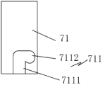
71-套管71-casing
711-栓槽711-key slot
7111-第一槽体部7111-The first tank body
7112-第二槽体部7112-Second tank body
72-插销72-Lock
721-销头721-pin head
7211-安装部7211-Installation Department
722-销体722-pin body
73-销栓73-Pin
80-挂锁装置80 - padlock device
L1-第一距离L1 - first distance
L2-套管的长度L2 - the length of the casing
L3-插销的长度L3-Length of the pin
L4-销体的长度L4-the length of the pin body
具体实施方式 Detailed ways
下面结合附图和具体实施例对本实用新型技术方案进行详细的描述,以更进一步了解本实用新型的目的、方案及功效,但并非作为本实用新型所附权利要求保护范围的限制。The technical scheme of the utility model is described in detail below in conjunction with the accompanying drawings and specific embodiments, so as to further understand the purpose, scheme and effect of the utility model, but not as a limitation of the scope of protection of the appended claims of the utility model.
需要说明的是,本实用新型的应急舱口盖的结构图与现有技术的应急舱口盖结构图大致相同,为了避免重复,在对现有技术的应急舱口盖进行描述时也采用了图1。It should be noted that the structural diagram of the emergency hatch cover of the utility model is roughly the same as that of the prior art emergency hatch cover. In order to avoid repetition, the emergency hatch cover of the prior art is also described in figure 1.
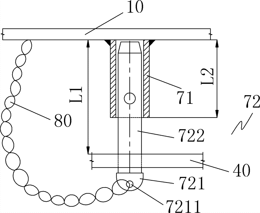
参阅图1及图2,如图所示,本实用新型的应急舱口盖包括盖板10和锁装置70。盖板10上穿设有安装轴20,安装轴20上相对盖板10的内外两端上均设有手轮30、30′,且安装轴20上还设置有联动装置40,联动装置40与盖板10之间具有一第一距离L1(见图3)。联动装置40包括本体41、第一联动杆42、第二联动杆43、第三联动杆44、第四联动杆45,本体41套设在安装轴20上,第一联动杆42为多根,均匀分布在本体41的外缘上(图2中给出的第一联动杆为四根,在实际使用中并不局限于此),每一第一联动杆42的远离本体41的一端上铰接一根第二联动杆43,第二联动杆43的远离第一联动杆42的一端上铰接一根第三联动杆44,每一第三联动杆44的两端分别铰接一根第四联动杆45,且第二联动杆43与第三联动杆44的铰接位置同于第三联动杆44与第四联动杆45的铰接位置,每一第四联动杆45的远离第三联动杆43的一端具有楔形部451,每一楔形部451与一限位楔块60对应,限位楔块60设置在围板50上,且联动装置40具有一使楔形部451脱离限位楔块60的开启方向ω。锁装置70设置在盖板10上且位于一限制联动装置40朝开启方向(图2中的ω方向)旋转的位置上,该位置没有局限,只要是任意一能限制联动装置40朝开启方向旋转的位置均可。Referring to FIG. 1 and FIG. 2 , as shown in the figures, the emergency hatch cover of the present invention includes a
结合参阅图3、图4和图5,锁装置70包括套管71和插销72,为了能达到限制联动装置40朝开启方向旋转的目的,套管71的长度L2小于第一距离L1,插销L3的长度大于第一距离L1。套管71固定于盖板10上(具体固定方式可以采取如焊接方式),且套管71的管壁上具有一栓槽711,较佳地,栓槽711包括第一槽体部7111和第二槽体部7112,第一槽体部7111沿套管71的轴向设置,第二槽体部7112沿套管71的周向设置。插销72与套管71对应,且插销72上突出一与栓槽711对应的销栓73,插销72包括销头721及销体722,销栓73位于销体722上,销头721上具有一安装部7211,较佳地,销体722的长度L4大于第一距离L1。Referring to Fig. 3, Fig. 4 and Fig. 5, the
另外,为了方便锁装置的使用,盖板10上设置有一挂锁装置80,该挂锁装置80的远离盖板10一端设置在安装部7211上。当然,此处的挂锁装置80也可以为锁装置70上自带的小链。In addition, in order to facilitate the use of the lock device, a
本实用新型的应急舱口盖通过锁装置70的设置,于关闭盖体10后、插销72插入套管71、销栓73卡入栓槽711时,将限制联动装置40的开启方向,外部人员无法打开盖体10,从而满足了《国际船舶和港口实施保安规则》的要求,且方便、可靠还可满足应急状态下逃生需求。The emergency hatch cover of the present utility model is provided with the locking
当然,本实用新型还可有其它多种实施例,在不背离本实用新型精神及其实质的情况下,熟悉本领域的技术人员当可根据本实用新型作出各种相应的改变和变形,但这些相应的改变和变形都应属于本实用新型所附的权利要求的保护范围。Of course, the utility model can also have other various embodiments, and those skilled in the art can make various corresponding changes and deformations according to the utility model without departing from the spirit and essence of the utility model, but These corresponding changes and deformations should all belong to the protection scope of the appended claims of the present utility model.
Claims (10)
Priority Applications (1)
| Application Number | Priority Date | Filing Date | Title |
|---|---|---|---|
| CN 201220052989 CN202491908U (en) | 2012-02-17 | 2012-02-17 | Lock device applied to emergency cabin covering cap and emergency cabin covering cap including the same |
Applications Claiming Priority (1)
| Application Number | Priority Date | Filing Date | Title |
|---|---|---|---|
| CN 201220052989 CN202491908U (en) | 2012-02-17 | 2012-02-17 | Lock device applied to emergency cabin covering cap and emergency cabin covering cap including the same |
Publications (1)
| Publication Number | Publication Date |
|---|---|
| CN202491908U true CN202491908U (en) | 2012-10-17 |
Family
ID=46998145
Family Applications (1)
| Application Number | Title | Priority Date | Filing Date |
|---|---|---|---|
| CN 201220052989 Expired - Fee Related CN202491908U (en) | 2012-02-17 | 2012-02-17 | Lock device applied to emergency cabin covering cap and emergency cabin covering cap including the same |
Country Status (1)
| Country | Link |
|---|---|
| CN (1) | CN202491908U (en) |
Cited By (3)
| Publication number | Priority date | Publication date | Assignee | Title |
|---|---|---|---|---|
| CN104340337A (en) * | 2014-10-16 | 2015-02-11 | 广州广船国际股份有限公司 | Water retaining tooling for service hole of vessel |
| KR101763814B1 (en) | 2015-09-17 | 2017-08-01 | 삼성중공업(주) | Helideck |
| CN115593566A (en) * | 2022-10-18 | 2023-01-13 | 中船黄埔文冲船舶有限公司(Cn) | Outward protruding hatch cover and opening and closing method thereof |
-
2012
- 2012-02-17 CN CN 201220052989 patent/CN202491908U/en not_active Expired - Fee Related
Cited By (3)
| Publication number | Priority date | Publication date | Assignee | Title |
|---|---|---|---|---|
| CN104340337A (en) * | 2014-10-16 | 2015-02-11 | 广州广船国际股份有限公司 | Water retaining tooling for service hole of vessel |
| KR101763814B1 (en) | 2015-09-17 | 2017-08-01 | 삼성중공업(주) | Helideck |
| CN115593566A (en) * | 2022-10-18 | 2023-01-13 | 中船黄埔文冲船舶有限公司(Cn) | Outward protruding hatch cover and opening and closing method thereof |
Similar Documents
| Publication | Publication Date | Title |
|---|---|---|
| US20150184543A1 (en) | Fan cowl locking system | |
| CN202491908U (en) | Lock device applied to emergency cabin covering cap and emergency cabin covering cap including the same | |
| CN104192293B (en) | A kind of equipment hatch door mechanism of thin wall-type Modeling of Complex Surface unmanned vehicle | |
| CN103328745B (en) | Three re-detection double locking impeller | |
| CN102020000B (en) | Ship hatch cover | |
| CN105253257A (en) | Marine inclined ladder door/cover | |
| CN108019104B (en) | Steel door handle lock | |
| CN104018769B (en) | Integrally dismountable window protective guard | |
| CN203066686U (en) | Anti-theft device used for fan tower door | |
| CN204895773U (en) | Little hatch board is opened and close fast and is prevented pirate's device | |
| CN211818173U (en) | Entrance to a cave protector is reserved to floor | |
| CN104963606B (en) | A kind of C-frame double crank swing-in hidden safety door | |
| CN219619911U (en) | Tank container and valve protection box thereof | |
| CN102889028B (en) | Escaping lock with improved structure | |
| CN104989196A (en) | Single-column double-point inward-opening invisible safety gate link mechanism | |
| CN207045615U (en) | A kind of moon pool bottom fastening system | |
| US10156086B2 (en) | Dual entry safety cuff port | |
| CN204877161U (en) | Open stealthy emergency exit in single -column is two | |
| CN209413556U (en) | a kind of handcuffs | |
| KR20120124836A (en) | Manhole unit for citadel | |
| CN211643311U (en) | Container door and container with same | |
| CN207747585U (en) | Card printer can draw and insert-type lock safety into cartridge | |
| US2267704A (en) | Door lock | |
| CN218777657U (en) | Portable grid lid is inhaled to marine magnetism | |
| CN222162400U (en) | Manhole door and flue gas denitration reactor |
Legal Events
| Date | Code | Title | Description |
|---|---|---|---|
| C14 | Grant of patent or utility model | ||
| GR01 | Patent grant | ||
| CF01 | Termination of patent right due to non-payment of annual fee | ||
| CF01 | Termination of patent right due to non-payment of annual fee |
Granted publication date: 20121017 Termination date: 20160217 |