CN202491064U - Device for automatically separating pin shaft from cut shaft dust - Google Patents
Device for automatically separating pin shaft from cut shaft dust Download PDFInfo
- Publication number
- CN202491064U CN202491064U CN2012200799222U CN201220079922U CN202491064U CN 202491064 U CN202491064 U CN 202491064U CN 2012200799222 U CN2012200799222 U CN 2012200799222U CN 201220079922 U CN201220079922 U CN 201220079922U CN 202491064 U CN202491064 U CN 202491064U
- Authority
- CN
- China
- Prior art keywords
- pin shaft
- shaft
- pin
- collection mechanism
- cutting
- Prior art date
- Legal status (The legal status is an assumption and is not a legal conclusion. Google has not performed a legal analysis and makes no representation as to the accuracy of the status listed.)
- Expired - Fee Related
Links
Images

Classifications
-
- Y—GENERAL TAGGING OF NEW TECHNOLOGICAL DEVELOPMENTS; GENERAL TAGGING OF CROSS-SECTIONAL TECHNOLOGIES SPANNING OVER SEVERAL SECTIONS OF THE IPC; TECHNICAL SUBJECTS COVERED BY FORMER USPC CROSS-REFERENCE ART COLLECTIONS [XRACs] AND DIGESTS
- Y02—TECHNOLOGIES OR APPLICATIONS FOR MITIGATION OR ADAPTATION AGAINST CLIMATE CHANGE
- Y02P—CLIMATE CHANGE MITIGATION TECHNOLOGIES IN THE PRODUCTION OR PROCESSING OF GOODS
- Y02P70/00—Climate change mitigation technologies in the production process for final industrial or consumer products
- Y02P70/10—Greenhouse gas [GHG] capture, material saving, heat recovery or other energy efficient measures, e.g. motor control, characterised by manufacturing processes, e.g. for rolling metal or metal working
Landscapes
- Processing And Handling Of Plastics And Other Materials For Molding In General (AREA)
Abstract
本实用新型公开了一种销轴切制轴屑自动分离装置,它包括机架、销轴切制装置、销轴固定装置、轴屑分离装置,销轴固定装置固定在机架上,销轴固定装置与销轴切制装置配合,所述轴屑分离装置包括销轴收集机构、毛刺收集机构,所述毛刺收集机构设置在销轴机腔体内部,对应在销轴切制装置下方,对切制好的销轴进行收集的销轴收集机构设置在毛刺收集机构上端,销轴收集机构终端延伸到销轴机的外面。该装置使销轴切制时销轴与铁屑自动分离,保证了销轴的加工质量,提高了链条耐磨性能,提高发动机的性能指标和可靠性以及使用寿命。
The utility model discloses an automatic separation device for pin shaft cutting and cutting shaft chips, which comprises a frame, a pin shaft cutting device, a pin shaft fixing device, and a shaft chip separating device. The pin shaft fixing device is fixed on the frame, and the pin shaft The fixing device cooperates with the pin shaft cutting device. The shaft chip separation device includes a pin shaft collection mechanism and a burr collection mechanism. The burr collection mechanism is arranged inside the pin shaft machine cavity, corresponding to the pin shaft cutting device below, for The pin shaft collection mechanism for collecting the cut pin shafts is arranged on the upper end of the burr collection mechanism, and the terminal of the pin shaft collection mechanism extends to the outside of the pin shaft machine. The device automatically separates the pin shaft from the iron filings when the pin shaft is cut, which ensures the processing quality of the pin shaft, improves the wear resistance of the chain, and improves the performance index, reliability and service life of the engine.
Description
技术领域 technical field
本实用新型属于链条生产过程中使用的销轴机,具体涉及一种适用于发动机链条销轴切制销轴与刮削铁屑的分离装置。The utility model belongs to a pin machine used in the chain production process, in particular to a separation device suitable for cutting pin shafts of engine chain pins and scraping iron scraps.
背景技术 Background technique
发动机链条因其应用场合的需要,链条性能要求非常严格,所以对链条的制作要求也很严格,其零件制作质量的优劣直接决定着链条装配质量的优劣。尤其是链条销轴端面质量,直接决定着链条装配框架的质量,其端面要求切断后进行双面刮削,目前,销轴切制刮削后产生的毛刺连同销轴混在一起,给销轴带来很大的质量隐患,进而对链条耐磨性能带来很大的质量隐患。Due to the needs of the application of the engine chain, the performance requirements of the chain are very strict, so the requirements for the production of the chain are also very strict. The quality of its parts directly determines the quality of the chain assembly. Especially the quality of the end face of the chain pin shaft directly determines the quality of the chain assembly frame. The end face is required to be cut and then scraped on both sides. At present, the burrs generated after the pin shaft is cut and scraped are mixed together with the pin shaft, which brings great damage to the pin shaft. Large quality hidden dangers, and then bring great quality hidden dangers to the wear resistance of the chain.
发明内容 Contents of the invention
为了克服现有技术领域存在的上述问题,本实用新型的目的在于,提供一种销轴切制轴屑自动分离装置,解决由于切制销轴与刮削铁屑混在一起不能分离而导致的影响销轴质量的问题。In order to overcome the above-mentioned problems existing in the prior art field, the purpose of this utility model is to provide an automatic separation device for cutting pins and chips, which can solve the problem that the pins cannot be separated due to the mixing of the cutting pins and the scraping iron chips. Shaft quality issues.
本实用新型提供的销轴切制轴屑自动分离装置,销轴机包括机架、销轴切制装置、销轴固定装置、轴屑分离装置,销轴固定装置固定在机架上,销轴固定装置与销轴切制装置配合,所述轴屑分离装置包括销轴收集机构、毛刺收集机构,所述轴屑分离装置包括销轴收集机构、毛刺收集机构,所述毛刺收集机构设置在销轴机腔体内部,对应在销轴切制装置下方,对切制好的销轴进行收集的销轴收集机构设置在毛刺收集机构上端,销轴收集机构终端延伸到销轴机的外面。所述的销轴收集机构包括落料漏斗、出料管、销轴料盒,所述落料漏斗固定在机架上,对应设置在销轴切制装置终端刀具的下方略前的位置,落料漏斗的底部设有出料口,出料口与出料管一端连接,出料管的另一端与设置在销轴机外部的销轴料盒连接。所述的毛刺收集机构即毛刺盒,毛刺盒设置在销轴收集机构的落料漏斗下端,毛刺盒内部设有可过滤毛刺的过滤网。The utility model provides an automatic separation device for pin shaft cutting and cutting shaft chips. The pin shaft machine includes a frame, a pin shaft cutting device, a pin shaft fixing device, and a shaft chip separating device. The pin shaft fixing device is fixed on the frame. The fixing device cooperates with the pin shaft cutting device. The shaft chip separation device includes a pin shaft collection mechanism and a burr collection mechanism. The shaft chip separation device includes a pin shaft collection mechanism and a burr collection mechanism. The burr collection mechanism is arranged on the pin Inside the shaft machine cavity, corresponding to the lower part of the pin cutting device, the pin collecting mechanism for collecting the cut pins is set at the upper end of the burr collecting mechanism, and the terminal of the pin collecting mechanism extends to the outside of the pin machine. The pin shaft collection mechanism includes a blanking funnel, a discharge pipe, and a pin shaft material box. The blanking funnel is fixed on the frame, and is correspondingly arranged at a position slightly before the terminal cutter of the pin shaft cutting device. The bottom of the material funnel is provided with a discharge port, the discharge port is connected with one end of the discharge pipe, and the other end of the discharge pipe is connected with the pin shaft material box arranged outside the pin shaft machine. The burr collecting mechanism is a burr box, the burr box is arranged at the lower end of the blanking funnel of the pin shaft collecting mechanism, and the burr box is provided with a filter screen capable of filtering burrs.
本实用新型提供的销轴切制轴屑自动分离装置,其有益效果在于,该装置使销轴切制时销轴与铁屑自动分离,保证了销轴的加工质量,提高了链条耐磨性能,提高发动机的性能指标和可靠性以及使用寿命。The utility model provides an automatic separation device for pin shaft cutting and scraps, and its beneficial effect is that the device can automatically separate the pin shaft and iron filings when the pin shaft is cut, which ensures the processing quality of the pin shaft and improves the wear resistance of the chain. , Improve the performance index, reliability and service life of the engine.
附图说明 Description of drawings
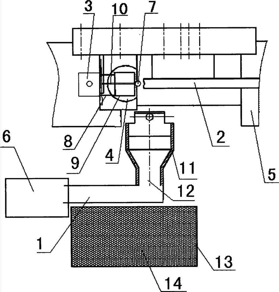
图1是本实用新型实施例的整体结构示意图。Fig. 1 is a schematic diagram of the overall structure of an embodiment of the utility model.
图中标注:Labeled in the figure:
1.出料管;2.靠山;3.固定刀口;4.活动刀口;5.滑块;6.销轴料盒;7.销轴;8.移位刀;9.刮刀;10.顶针;11.落料漏斗;12.出料口;13.毛刺盒;14.过滤网。1. Discharge pipe; 2. Backing; 3. Fixed knife edge; 4. Movable knife edge; 5. Slider; 6. Pin shaft material box; 7. Pin shaft; 8. Shift knife; ; 11. Blanking funnel; 12. Outlet; 13. Burr box; 14. Filter.
具体实施方式 Detailed ways
下面参照附图,结合实施例,对本实用新型提供的销轴切制轴屑自动分离装置,进行详细的说明。Referring to the accompanying drawings and examples, the automatic separation device for cutting shaft scraps provided by the utility model will be described in detail.
实施例Example
参照图1,本实施例的销轴切制轴屑自动分离装置,销轴机包括机架、销轴切制装置、销轴固定装置、轴屑分离装置,销轴固定装置固定在机架上,销轴固定装置与销轴切制装置配合,所述轴屑分离装置包括销轴收集机构、毛刺收集机构,所述轴屑分离装置包括销轴收集机构、毛刺收集机构,所述毛刺收集机构设置在销轴机腔体内部,对应设置在销轴切制装置下方,对切制好的销轴进行收集的销轴收集机构设置在毛刺收集机构上端,销轴收集机构终端延伸到销轴机的外面。所述的销轴收集机构包括落料漏斗11、出料管1、销轴料盒6,所述落料漏斗11固定在机架上,对应设置在销轴切制装置终端刀具的下方略前的位置,落料漏斗11的底部设有出料口12,出料口12与出料管1一端连接,出料管1的另一端与设置在销轴机外部的销轴料盒6连接。所述的毛刺收集机构即毛刺盒13,毛刺盒13设置在销轴收集机构的落料漏斗11下端,毛刺盒13内部设有可过滤毛刺的过滤网14。With reference to Fig. 1, the pin shaft cutting automatic scrap separation device of the present embodiment, the pin shaft machine includes a frame, a pin shaft cutting device, a pin shaft fixing device, and a shaft chip separating device, and the pin shaft fixing device is fixed on the frame , the pin shaft fixing device cooperates with the pin shaft cutting device, the shaft chip separation device includes a pin shaft collection mechanism, a burr collection mechanism, the shaft chip separation device includes a pin shaft collection mechanism, a burr collection mechanism, and the burr collection mechanism It is installed inside the cavity of the pin shaft machine, and is correspondingly installed under the pin shaft cutting device. The pin shaft collection mechanism for collecting the cut pin shafts is set on the upper end of the burr collection mechanism, and the terminal of the pin shaft collection mechanism extends to the pin shaft machine. outside. The pin shaft collection mechanism includes a
所述销轴固定装置包括滑块5、靠山2、固定刀口3,滑块5与机架中的一根输出轴连接,靠山2通过弹簧固定在机架上,固定刀口3通过固定刀口座固定在机架上,固定刀口3与靠山2相配合。所述销轴切制装置包括活动刀口4、移位刀8、刮刀9,活动刀口4通过活动刀口座固定在滑块5上,与靠山2配合,移位刀8固定在滑块5上,随滑块5移动,刮刀9固定在机架上。它还包括顶针10,设置在销轴切制装置的活动刀口4内部,其后端设有通过弹簧片固定在滑块5上的弹簧。The pin fixing device includes a
进行销轴切制时,开始送料首先销轴料进入销轴机,由靠山2顶住销轴料,固定刀口3固定销轴料,活动刀口4向前移动,销轴机凸轮转动带动滑块5做往复运动,活动刀口4通过活动刀口座固定在滑块5上,在滑块5和活动刀口4的冲击下销轴料1被切断;活动刀口4与靠山2夹着切下的销轴7向前移动到移位刀8的位置,移位刀8挤推销轴7,使销轴7两边的余量均匀,能够均匀的受到刮刀9刮削的作用,活动刀口4与靠山2继续夹着销轴7前行,经过刮刀9,将销轴7两端平面刮平刮亮;刮削后的销轴7通过刮刀9后,靠山2后撤,活动刀口4内置的顶针10将销轴顶落在落料漏斗11里,落料漏斗11下端的出料口12连接出料管1,出料管1一直延伸到销轴机外,与销轴机前面的销轴料盒6连接,销轴7落到销轴料盒6内,而收集毛刺的毛刺盒13是在落料漏斗11下面,比落料漏斗11大许多,它里面设有过滤网14,切削时毛刺随着切削液一起落到毛刺盒13内,切削液通过过滤网14滤出,毛刺被过滤网14挡住,定期清理过滤网14上的毛刺即可。通过在销轴7切制过程中刮刀9的运动方向即销轴7切制经刮削后下落的方向与刮削形成毛刺的方向反向来进行轴屑自动分离,该装置使销轴7切制时销轴7与毛刺自动分离,保证了销轴7的加工质量,提高了链条耐磨性能,提高发动机的性能指标和可靠性以及使用寿命。When pin cutting is performed, the pin material enters the pin machine at the beginning of feeding, and the pin material is supported by the
Claims (3)
Priority Applications (1)
| Application Number | Priority Date | Filing Date | Title |
|---|---|---|---|
| CN2012200799222U CN202491064U (en) | 2012-03-06 | 2012-03-06 | Device for automatically separating pin shaft from cut shaft dust |
Applications Claiming Priority (1)
| Application Number | Priority Date | Filing Date | Title |
|---|---|---|---|
| CN2012200799222U CN202491064U (en) | 2012-03-06 | 2012-03-06 | Device for automatically separating pin shaft from cut shaft dust |
Publications (1)
| Publication Number | Publication Date |
|---|---|
| CN202491064U true CN202491064U (en) | 2012-10-17 |
Family
ID=46997307
Family Applications (1)
| Application Number | Title | Priority Date | Filing Date |
|---|---|---|---|
| CN2012200799222U Expired - Fee Related CN202491064U (en) | 2012-03-06 | 2012-03-06 | Device for automatically separating pin shaft from cut shaft dust |
Country Status (1)
| Country | Link |
|---|---|
| CN (1) | CN202491064U (en) |
Cited By (1)
| Publication number | Priority date | Publication date | Assignee | Title |
|---|---|---|---|---|
| CN103753338A (en) * | 2014-01-07 | 2014-04-30 | 江苏大洋精锻有限公司 | Auxiliary device of smoothing machine |
-
2012
- 2012-03-06 CN CN2012200799222U patent/CN202491064U/en not_active Expired - Fee Related
Cited By (2)
| Publication number | Priority date | Publication date | Assignee | Title |
|---|---|---|---|---|
| CN103753338A (en) * | 2014-01-07 | 2014-04-30 | 江苏大洋精锻有限公司 | Auxiliary device of smoothing machine |
| CN103753338B (en) * | 2014-01-07 | 2016-09-14 | 江苏大洋精锻有限公司 | A kind of chamfering machine auxiliary device |
Similar Documents
| Publication | Publication Date | Title |
|---|---|---|
| CN219725231U (en) | Automobile welding seam polishing equipment | |
| CN202491064U (en) | Device for automatically separating pin shaft from cut shaft dust | |
| CN102362693B (en) | Core-removing and peeling machine for litchi fruits | |
| CN204771833U (en) | Lathe chip removal device | |
| CN116651902B (en) | Crushing mechanism for waste circuit boards | |
| CN220028573U (en) | A kind of molding sand impurity removal and cleaning equipment | |
| CN114321692B (en) | Thin oil station with magnetic filter oil return impurity filtering function | |
| CN209501899U (en) | A solid waste treatment device | |
| CN110124778B (en) | A multi-stage crushing material grinder | |
| CN209714864U (en) | A tailings slurry filter device | |
| CN117160096B (en) | Impurity filtering equipment for glass cement production | |
| CN104174197A (en) | Cutting scrap filter and collection device | |
| CN217180194U (en) | Food safety inspection uses novel sampling device | |
| CN217432240U (en) | A sorting unit for rice production | |
| CN104548699A (en) | Oil residue coarse filtration device | |
| CN112790255B (en) | Extrusion device for tea processing | |
| CN209829526U (en) | A classified screening device for brown corundum abrasive material | |
| CN202607719U (en) | Cutting and collecting device for rubber mat | |
| CN203663523U (en) | Crushing filtering device | |
| CN102716614A (en) | Automatic slag tapping device | |
| CN222221961U (en) | A piston rod processing drilling machine | |
| CN202823596U (en) | Autorotation type filter | |
| CN221514751U (en) | PBT material processing classifying and crushing device | |
| CN218890666U (en) | A kind of ore crushing device | |
| CN220753228U (en) | Magnetic ring pressing embryo collecting mechanism |
Legal Events
| Date | Code | Title | Description |
|---|---|---|---|
| C14 | Grant of patent or utility model | ||
| GR01 | Patent grant | ||
| C56 | Change in the name or address of the patentee | ||
| CP01 | Change in the name or title of a patent holder |
Address after: 266700, 112, Hongkong Road, Qingdao overseas Chinese science and Technology Park, Pingdu City, Shandong Province Patentee after: Qingdao Choho Industrial Co., Ltd. Address before: 266700, 112, Hongkong Road, Qingdao overseas Chinese science and Technology Park, Pingdu City, Shandong Province Patentee before: Qingdao Choho Industrial Co., Ltd. |
|
| CF01 | Termination of patent right due to non-payment of annual fee |
Granted publication date: 20121017 Termination date: 20150306 |
|
| EXPY | Termination of patent right or utility model |