CN202411827U - Valve automatic drilling and tapping machine tool - Google Patents
Valve automatic drilling and tapping machine tool Download PDFInfo
- Publication number
- CN202411827U CN202411827U CN 201220039822 CN201220039822U CN202411827U CN 202411827 U CN202411827 U CN 202411827U CN 201220039822 CN201220039822 CN 201220039822 CN 201220039822 U CN201220039822 U CN 201220039822U CN 202411827 U CN202411827 U CN 202411827U
- Authority
- CN
- China
- Prior art keywords
- automatic drilling
- tapping
- cylinder
- base plate
- tapper
- Prior art date
- Legal status (The legal status is an assumption and is not a legal conclusion. Google has not performed a legal analysis and makes no representation as to the accuracy of the status listed.)
- Expired - Lifetime
Links
Images


Landscapes
- Drilling And Boring (AREA)
Abstract
The utility model provides a valve automatic drilling and tapping machine tool. The valve automatic drilling and tapping machine tool comprises a blanking mechanism, a workpiece positioning mechanism, an automatic drilling mechanism, an automatic tapping mechanism, a workpiece clamping mechanism, a main clamping cylinder, a tapping mechanism feed cylinder, a drilling mechanism driving screw rod, a workbench feed cylinder and a drilling mechanism feed servo motor, wherein blanking mechanism is vertically arranged on the base of the machine tool; the workpiece clamping mechanism is arranged at the bottom of the blanking mechanism and is connected with the main clamping cylinder and the workbench feed cylinder; the automatic drilling mechanism comprises a pair of coaxial and opposite automatic drilling power heads; the automatic tapping mechanism is parallel to the automatic drilling mechanism and comprises a pair of coaxial and opposite automatic tapping power heads; the automatic drilling power heads are connected with a servo motor through the drilling mechanism driving screw rod; and the automatic tapping power heads are connected with a cylinder. The valve automatic drilling and tapping machine tool is used for performing four-station automatic drilling and tapping, different parts can be machined in one procedure, and the production efficiency and the product percent of pass are improved.
Description
Technical field
The utility model relates to the technical field of valve processing equipment, particularly a kind of valve automatic drilling, tapper.
Background technology
Valve is the control assembly in the pipeline fluid transport system, have water conservancy diversion, by, regulate or function such as overflow release.
Existing machine tool adds man-hour at endoporus and screw thread to valve; A common end with lathe clamp mechanism pinch valve; The other end is holed and tapping processing, after machining, the two ends of valve are changed; To the processing with tapping of holing of the unprocessed other end, until accomplishing all positions that need process of valve.Thus, need pass through multiple working procedure, and adopt many universal machine tools to machine the processing of same valve.In each road manufacturing procedure, all need carry out clamping and correction, especially for the processing of the bigger valve body of some bores to processed valve body; Needing the large-scale lathe of replacing to wait processes; Increased machine and human cost, wasted time and energy, production efficiency and product percent of pass lower greatly.
In view of this, the utility model embodiment has proposed a kind of valve automatic drilling, tapper of four stations.
Summary of the invention
For solving the problems of the technologies described above, the purpose of the utility model embodiment realizes through following technical scheme:
Valve automatic drilling, tapper that the utility model provides; Comprise blanking mechanism, workpiece detent mechanism, automatic drilling mechanism, self-tapping mechanism, workpiece clamping mechanism, main cylinder, tapper mechanism feeding cylinder, borehole drill construction drive lead screw, table feed cylinder, the borehole drill construction feed servo motor of clamping; Said blanking mechanism is vertically set on the base of lathe; Said workpiece clamping mechanism is arranged on the bottom of blanking mechanism; Said workpiece clamping mechanism connects main cylinder and the table feed cylinder of clamping; Said automatic drilling mechanism comprises a pair of coaxial and relative automatic drilling unit head, and said self-tapping mechanism is parallel with said automatic drilling mechanism position, comprises a pair of coaxial and relative self-tapping power head; Said automatic drilling unit head respectively is connected with borehole drill construction feed servo motor through the borehole drill construction drive lead screw; Said driven by servomotor borehole drill construction drive lead screw moves to the processing stations of setting with the automatic drilling unit head, and two said self-tapping power heads respectively connect a tapper mechanism feeding cylinder, and said tapper mechanism feeding air cylinder driven self-tapping power head moves to the processing stations of setting.
Preferably; Also comprise Strok mechanism; Said Strok mechanism comprises the line slideway that is installed in the middle of the lathe base, be connected stroke base plate on the line slideway, clamp base plate, be fixed on compressing block, be fixed on the compact heap base plate that clamps on the base plate, be fixed on the compact heap base plate and compress the compact heap on the block on the stroke base plate; Said line slideway constitutes vertical position relation with tapper mechanism and drilling machine; Said table feed cylinder is connected in the stroke base plate through a contiguous block, and the said main cylinder that clamps is fixed on the clamping base plate through plate.
Preferably; Said automatic drilling mechanism also comprises the bearing of the V band of big belt pulley, small belt pulley, connection big belt pulley and small belt pulley, the stepper motor that is connected with small belt pulley, axle, installation shaft; The top of said axle is equipped with the automatic drilling unit head; Said big belt pulley is installed on the axle, and said axle and bearing are installed in the one shell.
Preferably; Said automatic drilling mechanism also comprises the guide rail that is installed on the lathe base, is arranged on the boring base plate on the guide rail, the ball screw that is connected with the boring base plate, the servomotor that is connected with ball-screw, said be equipped with spool and the body shell of bearing is arranged on the boring base plate.
Preferably, said servomotor is connected with ball screw through shaft coupling, and said servomotor is installed on the electric baseboard, and said electric baseboard is installed on the lathe base through securing member.
Preferably, said ball screw is installed on the screw mandrel shaft block, and said screw mandrel shaft block is installed on the lathe base through securing member.
Preferably, said ball screw links together through ball nut mount and boring base plate.
Preferably; Said self-tapping mechanism also comprises the bearing of the V band of big belt pulley, small belt pulley, connection big belt pulley and small belt pulley, the stepper motor that is connected with small belt pulley, axle, installation shaft; The top of said axle is equipped with the automatic drilling unit head; Said big belt pulley is installed on the axle, and said axle and bearing are installed in the one shell.
Preferably, said self-tapping mechanism also comprises the guide rail that is installed on the lathe base, be arranged on tapping base plate on the guide rail, with the cylinder that the tapping base plate is connected, the said body shell that axle and bearing are installed is arranged on the tapping base plate.
Preferably, said cylinder is installed on the cylinder mounting plate, and said cylinder mounting plate is installed on the lathe base through securing member, and an end of a cylinder block is connected with the piston rod of cylinder, and the other end of said cylinder block is fixed on the tapping base plate through securing member.
Valve automatic drilling, tapper that the utility model provides; Through two automatic drilling unit heads and two parallel with it self-tapping power heads; Workpiece is carried out the automatic drilling of four stations and the processing of tapping; One procedure can be accomplished the processing of different parts, has practiced thrift machine and human cost, has improved production efficiency and product percent of pass.
Description of drawings
Fig. 1 is the perspective view of the utility model valve automatic drilling, tapper;
Fig. 2 is the plan structure sketch map of the utility model valve automatic drilling, tapper;
Fig. 3 is the structural representation of the Strok mechanism of the utility model valve automatic drilling, tapper;
Fig. 4 is the structural representation of the detent mechanism of the utility model valve automatic drilling, tapper;
Fig. 5 is the structural representation of the tapper mechanism of the utility model valve automatic drilling, tapper.
The specific embodiment
The utility model provides a kind of valve automatic drilling, tapper.Said valve automatic drilling, tapper comprise blanking mechanism, workpiece detent mechanism, automatic drilling mechanism, self-tapping mechanism, workpiece clamping mechanism, main cylinder, tapper mechanism feeding cylinder, borehole drill construction drive lead screw, table feed cylinder, the borehole drill construction feed servo motor of clamping; Said blanking mechanism is vertically set on the base of lathe; Said workpiece clamping mechanism is arranged on the bottom of blanking mechanism; Said workpiece clamping mechanism connects main cylinder and the table feed cylinder of clamping; Said automatic drilling mechanism comprises a pair of coaxial and relative automatic drilling unit head; Said self-tapping mechanism is parallel with said automatic drilling mechanism position; Comprise a pair of coaxial and relative self-tapping power head, said automatic drilling unit head respectively is connected with borehole drill construction feed servo motor through the borehole drill construction drive lead screw, and said driven by servomotor borehole drill construction drive lead screw moves to the automatic drilling unit head processing stations of setting; Two said self-tapping power heads respectively connect a tapper mechanism feeding cylinder, and said tapper mechanism feeding air cylinder driven self-tapping power head moves to the processing stations of setting.
Further describe below in conjunction with specific embodiment.
Please consult Fig. 1 and Fig. 2 in the lump, be the utility model valve automatic drilling, tapper perspective view and plan structure sketch map.
Said valve automatic drilling, tapper mainly comprise blanking mechanism 10, workpiece detent mechanism 20, automatic drilling mechanism 30, self-tapping mechanism 40, workpiece clamping mechanism 50, main cylinder 60, tapper mechanism feeding cylinder 70, borehole drill construction drive lead screw 80, table feed cylinder 90, the borehole drill construction feed servo motor 100 of clamping.
Said blanking mechanism 10 is vertically set on the base of lathe, vibrator feeder with the blank of copper valve in the blanking mechanism 10 of vibration feeding to lathe.
Said workpiece clamping mechanism 50 is arranged on the bottom of blanking mechanism 10, and workpiece leans on the gravity of self vertically to fall in blanking mechanism 10, gets into workpiece clamping mechanism 50.Said workpiece clamping mechanism 50 connects main cylinder 60 and the table feed cylinder 90 of clamping.
Said automatic drilling mechanism 30 comprises a pair of coaxial and relative automatic drilling unit head.Said self-tapping mechanism 40 is parallel with said automatic drilling mechanism 30 positions, comprises a pair of coaxial and relative self-tapping power head.
About two said automatic drilling unit heads respectively be connected with borehole drill construction feed servo motor 100 through borehole drill construction drive lead screw 80, said servomotor 80 driving borehole drill construction drive lead screws 80 move to automatic drilling unit head 30 processing stations of setting.
About two said self-tapping power heads respectively connect a tapper mechanism feeding cylinder 70, said tapper mechanism feeding cylinder 70 drives the processing stations that self-tapping power heads 40 move to setting.
Following brief account once lathe to the course of work of valve automatic drilling, tapping:
Vibrator feeder with copper valve blank vibration feeding to the blanking mechanism 10 of lathe; Workpiece clamping mechanism 50 makes zero under the effect of table feed cylinder 90, gets back to initial position, clamps under cylinder 60 effects main; Unclamp workpiece clamping mechanism 50; When workpiece gets into workpiece clamping mechanism 50, main cylinder 60 control workpiece clamping mechanism 50 clamping work pieces that clamp, table feed cylinder 90 control workpiece clamping mechanism 50 are with the shaft core position of workpiece motion s to the automatic drilling unit head of setting then; Predefined programme-control servomotor 100 drives borehole drill construction drive lead screw 80 the automatic drilling unit head is moved to station, and workpiece is carried out operations; After waiting to have bored the hole, table feed cylinder 90 moves the shaft core position that workpiece is moved to self-tapping power head once more, and tapper mechanism feeding cylinder 70 begins action self-tapping power head is urged to processing stations, and workpiece is carried out tapping processing.Wait machines the main cylinder 60 that clamps in back and unclamps with the auxiliary cylinder that clamps, and workpiece falls in the groove that connects material, so far whole lathe machining part.
See also Fig. 3, be the sketch map of the Strok mechanism of the utility model valve automatic drilling, tapper.
After workpiece to be processed gets into workpiece clamping mechanism 50 from blanking mechanism 10; Table feed cylinder 90 arrives workpiece motion s through one stroke mechanism controls workpiece clamping mechanism 50 shaft core position of the automatic drilling unit head of setting; The processing of holing; After drilling operating side accomplished, table feed cylinder 90 was controlled workpiece clamping mechanism 50 with the shaft core position of workpiece motion s to self-tapping power head through Strok mechanism once more, carries out tapping processing.
Below we introduce the structure and the operation principle of Strok mechanism.
Said Strok mechanism comprises line slideway 8, stroke base plate 7, compact heap 14 (15), compact heap base plate 11 and compresses block 17.
Base centre position at lathe is equipped with linear guide rail, and line slideway constitutes vertical position relation with tapper mechanism and drilling machine.
As shown in the figure, table feed cylinder 37 is connected in stroke base plate 7 through contiguous block 34.The main cylinder 24 that clamps is fixed on the clamping base plate 9 through plate 19.Said compact heap 14,15 is separately fixed at compact heap base plate 11 and compresses on the block 17, is fixed on the stroke base plate 7 and compress block 17, and compact heap base plate 11 is fixed on and clamps on the base plate 9.Said stroke base plate 7 is connected on the line slideway 8.
See also Fig. 4, be the structural representation of the borehole drill construction of the utility model valve automatic drilling, tapper.
Said automatic drilling mechanism 30 also comprises: big belt pulley 302, small belt pulley 309, stepper motor 314, axle 321, bearing 322, boring base plate 328, guide rail 331, servomotor 342, shaft coupling 340, screw mandrel 333, screw mandrel bearing 332, ball nut mount 334.
On the said big belt pulley 302 back-up ring 303 is installed.
Be connected with V between said big belt pulley 302 and the small belt pulley 309 and be with 308.
Said stepper motor 314 is installed on the motor mounting plate 312, and is connected with small belt pulley 309.
Said stepper motor 314 is three-phase mixing stepper motor.
Said belt pulley tensioning plate 317 is connected on the motor mounting plate 312 through screw.
Said big belt pulley 302 is installed on the axle 321, and said axle 321 is installed in the bearing 322.
Said axle 321 is installed in the body shell 318 with bearing 322.
Said body shell 318 is arranged on the boring base plate 328 through cushion block 326.
Said boring base plate 328 is arranged on the guide rail 331, can do round rectilinear motion along guide rail 331.Said guide rail 331 is a SBR ball line slideway, is installed on the lathe base.
Said servomotor 342 is installed on the electric baseboard 341, and said servomotor 342 is three-phase mixing stepper motor.Said electric baseboard 341 is installed on the lathe base through securing member.
Said servomotor 342 is connected with ball screw 333 through shaft coupling 340.
Said ball screw 333 is installed on the screw mandrel shaft block 332.
Said screw mandrel shaft block 332 is installed on the lathe base through securing member.
Said ball screw 333 links together through ball nut mount 334 and boring base plate 328.Said boring base plate 328 in the drive lower edge of screw mandrel 333 guide rail 331 do round rectilinear motion.
The top of said axle 321 is equipped with the automatic drilling unit head.Therefore the automatic drilling unit head is done high speed rotary motion under the drive of stepper motor 341 and big belt pulley 302, under the drive of screw mandrel 333, can do round rectilinear motion along guide rail 331.
See also Fig. 5, be the structural representation of the tapper mechanism of the utility model valve automatic drilling, tapper.
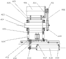
Said self-tapping mechanism 40 also comprises: big belt pulley 402, small belt pulley 411, stepper motor 416, axle 423, roller bearing 424, body shell 420, tapping base plate 431, guide rail 432, cylinder 438, cylinder block 434.
On the said big belt pulley 402 back-up ring 303 is installed.
Be connected with V between said big belt pulley 402 and the small belt pulley 411 and be with 408.
Said stepper motor 416 is installed on the motor mounting plate 414, and is connected with small belt pulley 411.
Said stepper motor 416 is three-phase mixing stepper motor.
Said belt pulley tensioning plate 419 is connected on the motor mounting plate 414 through screw.
Said big belt pulley 402 is installed on the axle 423, and said axle 423 is installed on the roller bearing 424.
Said tapping base plate 431 is arranged on the guide rail 432, can do round rectilinear motion along guide rail 432.Said guide rail 432 is a SBR ball line slideway.Said guide rail 432 is installed on the lathe base.
Said cylinder 438 is installed on cylinder mounting plate 437 and 439, and said cylinder mounting plate 437 and 439 is installed on the lathe base through securing member.
One end of said cylinder block 434 is connected with the piston rod of cylinder 438, and the other end of said cylinder block 434 is fixed on the tapping base plate 431 through securing member.Said tapping base plate 431 in the drive lower edge of cylinder piston rod guide rail 432 do round rectilinear motion.
The top of said axle 423 is equipped with self-tapping power head.Therefore self-tapping power head can be done round rectilinear motion along guide rail 432 under the drive of cylinder piston rod.
In sum; Valve automatic drilling, tapper that the utility model embodiment is provided; Through two automatic drilling unit heads and two parallel with it self-tapping power heads, workpiece is carried out the automatic drilling of four stations and the processing of tapping, one procedure can be accomplished the processing of different parts; Practice thrift machine and human cost, improved production efficiency and product percent of pass.
More than valve automatic drilling, tapper that the utility model embodiment is provided carried out detailed introduction; Used concrete example among this paper the principle and the embodiment of the utility model are set forth, the explanation of above embodiment just is used to help to understand the technical scheme that the utility model discloses; Simultaneously, for one of ordinary skill in the art, according to the thought of the utility model, the part that on the specific embodiment and range of application, all can change, in sum, this description should not be construed as the restriction to the utility model.
Claims (10)
1. a valve automatic drilling, tapper; It is characterized in that; Comprise blanking mechanism, workpiece detent mechanism, automatic drilling mechanism, self-tapping mechanism, workpiece clamping mechanism, main cylinder, tapper mechanism feeding cylinder, borehole drill construction drive lead screw, table feed cylinder, the borehole drill construction feed servo motor of clamping; Said blanking mechanism is vertically set on the base of lathe; Said workpiece clamping mechanism is arranged on the bottom of blanking mechanism, and said workpiece clamping mechanism connects main cylinder and the table feed cylinder of clamping, and said automatic drilling mechanism comprises a pair of coaxial and relative automatic drilling unit head; Said self-tapping mechanism is parallel with said automatic drilling mechanism position; Comprise a pair of coaxial and relative self-tapping power head, said automatic drilling unit head respectively is connected with borehole drill construction feed servo motor through the borehole drill construction drive lead screw, and said driven by servomotor borehole drill construction drive lead screw moves to the automatic drilling unit head processing stations of setting; Two said self-tapping power heads respectively connect a tapper mechanism feeding cylinder, and said tapper mechanism feeding air cylinder driven self-tapping power head moves to the processing stations of setting.
2. valve automatic drilling according to claim 1, tapper; It is characterized in that; Also comprise Strok mechanism; Said Strok mechanism comprises the line slideway that is installed in the middle of the lathe base, be connected stroke base plate on the line slideway, clamp base plate, be fixed on compressing block, be fixed on the compact heap base plate that clamps on the base plate, be fixed on the compact heap base plate and compress the compact heap on the block on the stroke base plate; Said line slideway constitutes vertical position relation with tapper mechanism and drilling machine, and said table feed cylinder is connected in the stroke base plate through a contiguous block, and the said main cylinder that clamps is fixed on the clamping base plate through plate.
3. valve automatic drilling according to claim 1, tapper; It is characterized in that; Said automatic drilling mechanism also comprises the bearing of the V band of big belt pulley, small belt pulley, connection big belt pulley and small belt pulley, the stepper motor that is connected with small belt pulley, axle, installation shaft; The top of said axle is equipped with the automatic drilling unit head, and said big belt pulley is installed on the axle, and said axle and bearing are installed in the one shell.
4. valve automatic drilling according to claim 3, tapper; It is characterized in that; Said automatic drilling mechanism also comprises the guide rail that is installed on the lathe base, is arranged on the boring base plate on the guide rail, the ball screw that is connected with the boring base plate, the servomotor that is connected with ball-screw, said be equipped with spool and the body shell of bearing is arranged on the boring base plate.
5. valve automatic drilling according to claim 4, tapper; It is characterized in that; Said servomotor is connected with ball screw through shaft coupling, and said servomotor is installed on the electric baseboard, and said electric baseboard is installed on the lathe base through securing member.
6. valve automatic drilling according to claim 4, tapper is characterized in that said ball screw is installed on the screw mandrel shaft block, and said screw mandrel shaft block is installed on the lathe base through securing member.
7. valve automatic drilling according to claim 4, tapper is characterized in that, said ball screw links together through ball nut mount and boring base plate.
8. valve automatic drilling according to claim 1, tapper; It is characterized in that; Said self-tapping mechanism also comprises the bearing of the V band of big belt pulley, small belt pulley, connection big belt pulley and small belt pulley, the stepper motor that is connected with small belt pulley, axle, installation shaft; The top of said axle is equipped with the automatic drilling unit head, and said big belt pulley is installed on the axle, and said axle and bearing are installed in the one shell.
9. valve automatic drilling according to claim 8, tapper; It is characterized in that; Said self-tapping mechanism also comprises the guide rail that is installed on the lathe base, be arranged on tapping base plate on the guide rail, with the cylinder that the tapping base plate is connected, the said body shell that axle and bearing are installed is arranged on the tapping base plate.
10. valve automatic drilling according to claim 9, tapper; It is characterized in that; Said cylinder is installed on the cylinder mounting plate; Said cylinder mounting plate is installed on the lathe base through securing member, and an end of a cylinder block is connected with the piston rod of cylinder, and the other end of said cylinder block is fixed on the tapping base plate through securing member.
Priority Applications (1)
| Application Number | Priority Date | Filing Date | Title |
|---|---|---|---|
| CN 201220039822 CN202411827U (en) | 2012-02-08 | 2012-02-08 | Valve automatic drilling and tapping machine tool |
Applications Claiming Priority (1)
| Application Number | Priority Date | Filing Date | Title |
|---|---|---|---|
| CN 201220039822 CN202411827U (en) | 2012-02-08 | 2012-02-08 | Valve automatic drilling and tapping machine tool |
Publications (1)
| Publication Number | Publication Date |
|---|---|
| CN202411827U true CN202411827U (en) | 2012-09-05 |
Family
ID=46736621
Family Applications (1)
| Application Number | Title | Priority Date | Filing Date |
|---|---|---|---|
| CN 201220039822 Expired - Lifetime CN202411827U (en) | 2012-02-08 | 2012-02-08 | Valve automatic drilling and tapping machine tool |
Country Status (1)
| Country | Link |
|---|---|
| CN (1) | CN202411827U (en) |
Cited By (10)
| Publication number | Priority date | Publication date | Assignee | Title |
|---|---|---|---|---|
| CN102528458A (en) * | 2012-02-08 | 2012-07-04 | 浙江大学台州研究院 | Automatic drilling and tapping machine tool for valves |
| CN103317162A (en) * | 2013-07-02 | 2013-09-25 | 河北科技大学 | Automatic-feeding four-working-position rebar connecting sleeve drilling machine |
| CN104148749A (en) * | 2014-08-25 | 2014-11-19 | 张伟 | Mobile servo control numerical control tapping machine |
| CN104209815A (en) * | 2014-09-23 | 2014-12-17 | 淄博长讯环保设备有限公司 | Multi-station continuous processing machine tool for valve plate and valve body |
| CN106141330A (en) * | 2016-08-30 | 2016-11-23 | 苏州市吴中区木渎晓云模具加工厂 | The screw thread process unit of valve upper cover processing line |
| CN107470913A (en) * | 2017-09-23 | 2017-12-15 | 浙江班尼戈流体控制有限公司 | A kind of punching of valve body processing and chasing bar |
| CN108788736A (en) * | 2018-07-18 | 2018-11-13 | 浙江巨龙自动化设备有限公司 | Magneto machining production line tapping machine |
| CN108994335A (en) * | 2018-07-26 | 2018-12-14 | 江苏圣龙智能科技有限公司 | A kind of bit pressure all-in-one machine of lock core |
| CN109648338A (en) * | 2018-12-29 | 2019-04-19 | 泛科轴承集团有限公司 | Full-automatic flange type bearing support drilling tapping machine |
| CN110293403A (en) * | 2019-07-11 | 2019-10-01 | 苏州耀玮彤机械有限公司 | A kind of double process equipments of drilling-tapping |
-
2012
- 2012-02-08 CN CN 201220039822 patent/CN202411827U/en not_active Expired - Lifetime
Cited By (14)
| Publication number | Priority date | Publication date | Assignee | Title |
|---|---|---|---|---|
| CN102528458A (en) * | 2012-02-08 | 2012-07-04 | 浙江大学台州研究院 | Automatic drilling and tapping machine tool for valves |
| CN103317162A (en) * | 2013-07-02 | 2013-09-25 | 河北科技大学 | Automatic-feeding four-working-position rebar connecting sleeve drilling machine |
| CN104148749A (en) * | 2014-08-25 | 2014-11-19 | 张伟 | Mobile servo control numerical control tapping machine |
| CN104209815B (en) * | 2014-09-23 | 2018-02-13 | 淄博长迅环保设备有限公司 | A kind of valve body valve plate multistation Continuous maching lathe |
| CN104209815A (en) * | 2014-09-23 | 2014-12-17 | 淄博长讯环保设备有限公司 | Multi-station continuous processing machine tool for valve plate and valve body |
| CN106141330A (en) * | 2016-08-30 | 2016-11-23 | 苏州市吴中区木渎晓云模具加工厂 | The screw thread process unit of valve upper cover processing line |
| CN107470913A (en) * | 2017-09-23 | 2017-12-15 | 浙江班尼戈流体控制有限公司 | A kind of punching of valve body processing and chasing bar |
| CN107470913B (en) * | 2017-09-23 | 2023-04-11 | 浙江班尼戈流体控制有限公司 | Punching and tapping device for valve body machining |
| CN108788736A (en) * | 2018-07-18 | 2018-11-13 | 浙江巨龙自动化设备有限公司 | Magneto machining production line tapping machine |
| CN108788736B (en) * | 2018-07-18 | 2023-11-17 | 浙江巨龙自动化设备股份有限公司 | Tapping machine for permanent magnet motor processing production line |
| CN108994335A (en) * | 2018-07-26 | 2018-12-14 | 江苏圣龙智能科技有限公司 | A kind of bit pressure all-in-one machine of lock core |
| CN109648338A (en) * | 2018-12-29 | 2019-04-19 | 泛科轴承集团有限公司 | Full-automatic flange type bearing support drilling tapping machine |
| CN109648338B (en) * | 2018-12-29 | 2023-09-22 | 泛科轴承集团有限公司 | Full-automatic flange type bearing seat drilling and tapping machine |
| CN110293403A (en) * | 2019-07-11 | 2019-10-01 | 苏州耀玮彤机械有限公司 | A kind of double process equipments of drilling-tapping |
Similar Documents
| Publication | Publication Date | Title |
|---|---|---|
| CN102528458A (en) | Automatic drilling and tapping machine tool for valves | |
| CN202411827U (en) | Valve automatic drilling and tapping machine tool | |
| CN101934387B (en) | Multi-station drilling machine for processing lockset | |
| CN106735412A (en) | The polyaxial multistation automatic drill hole milling assembly line of section bar and its processing method | |
| CN201516554U (en) | Mobile multi-station machining machine tool | |
| CN204036158U (en) | A kind of numerical control end surface machining tool | |
| CN202317651U (en) | Four-station gate valve digital control special machine | |
| CN204470970U (en) | A kind of cross axle processing unit (plant) | |
| CN101347911B (en) | Numerical control reverse direction machining aggregate machinery | |
| CN201744690U (en) | Multi-position drilling machine | |
| CN205166364U (en) | Automatic lock attaches screw machine | |
| CN201895222U (en) | Trumpet valve core piston processing machine | |
| CN215146971U (en) | Intelligent boring and drilling numerical control combined machine tool | |
| CN203140881U (en) | Vertical band saw machine | |
| CN202162413U (en) | Numerical control high-speed hole puncher | |
| CN106042103A (en) | Processing equipment of bamboo block and processing method thereof | |
| CN206425557U (en) | Double main shaft hilted broadsword tower numerically controlled lathes | |
| CN201264181Y (en) | Numerical control reverse direction machining aggregate machinery | |
| CN211517130U (en) | Automatic clamping manipulator | |
| CN203092127U (en) | Lathing and grinding combined machining machine tool | |
| CN103273085B (en) | Full-automatic precision numerical-control instrument lathe | |
| CN206455199U (en) | The polyaxial multistation automatic drill hole milling assembly line of section bar | |
| CN107263192A (en) | Guiding polypody is creeped feeding with high precision drive shaft mechanism | |
| CN204413690U (en) | A kind of machining hole fixture | |
| CN203356610U (en) | Automatic supplying and blanking mechanism of turning center |
Legal Events
| Date | Code | Title | Description |
|---|---|---|---|
| C14 | Grant of patent or utility model | ||
| GR01 | Patent grant | ||
| C56 | Change in the name or address of the patentee | ||
| CP02 | Change in the address of a patent holder |
Address after: Truman town Yuhuan County Taizhou city Zhejiang province 317605 Hu Xing Industrial Park (Wu Jiaduan) Chu Chau talent dream factory Patentee after: Research Institute of Zhejiang University-Taizhou Address before: 317600 Yuhuan County Zhejiang Automobile & Motorcycle Industrial Zone Zhejiang Taizhou Motorcycle & motorcycle Research Institute Patentee before: Research Institute of Zhejiang University-Taizhou |
|
| CX01 | Expiry of patent term | ||
| CX01 | Expiry of patent term |
Granted publication date: 20120905 |