CN202406476U - Lightweight cultivating machine - Google Patents
Lightweight cultivating machine Download PDFInfo
- Publication number
- CN202406476U CN202406476U CN2011205359722U CN201120535972U CN202406476U CN 202406476 U CN202406476 U CN 202406476U CN 2011205359722 U CN2011205359722 U CN 2011205359722U CN 201120535972 U CN201120535972 U CN 201120535972U CN 202406476 U CN202406476 U CN 202406476U
- Authority
- CN
- China
- Prior art keywords
- assembly
- transmission case
- rotary blade
- transmission
- case assembly
- Prior art date
- Legal status (The legal status is an assumption and is not a legal conclusion. Google has not performed a legal analysis and makes no representation as to the accuracy of the status listed.)
- Expired - Fee Related
Links
Images


Landscapes
- Agricultural Machines (AREA)
Abstract
The utility model discloses a lightweight cultivating machine, which comprises a tail wheel assembly (1), a mud guard assembly (2), a left rotary blade set (3), a right rotary blade set (3), a coulter and transmission case assembly (4), connectors (5), a left drive wheel assembly (6), a right drive wheel assembly (6), a frame assembly (7), a clutch housing (8), a diesel engine (9), a clutch assembly (10), a transmission case assembly (11) and an operating mechanism assembly (12). The drive wheel assemblies (6) correspond to the left and the right rotary blade sets (3) for front driving. The left and the right rotary blade sets (3) correspond to the drive wheel assemblies (6) for rear ploughing. The transmission case assembly (11) tilts back by a certain angle relative to a drive shaft. The middle bottom of the transmission case assembly (11) is connected with the transmission case assembly (4) through the connectors (5). The transmission case assembly (11) and the transmission case assembly (4) form a triangular stable structure. The lightweight cultivating machine has the advantages of compact structure, small size, light weight, convenience and flexibility in operation and the like, is applicable to operations in south hilly areas, such as paddy fields, arid lands, sloping lands and vegetable fields, and is genuinely and agriculturally mechanical.
Description
Technical field
The utility model relates to a kind of agricultural tillage machinery, particularly a kind of light-duty harvesting and tillage machine.
Background technology
Light-duty harvesting and tillage machine is as agricultural tillage machinery, is applicable to that mainly paddy field, southern hills area, nonirrigated farmland, hillside fields, vegetable field and gardens loosen the soil, and present light-duty harvesting and tillage machine mainly contains three types on driving, the preceding cultivated rear-guard type of rotary blade group and chain side biography type.The rotary blade group is driving: directly drives rotary blade group workpiece, is characterized in simple in structure by live axle, and cheap, but owing to do not have driving wheel and steering mechanism, the operation effort, tractor driver's labour intensity is bigger.Before plough the rear-guard type: the rotary blade group is preceding, driving wheel after, tilth is difficult to control, the rotary blade group is prone to pierce in the soil so that flame-out.Chain side biography type: the output of gearbox power adopts the chain side to pass, and structure is loose relatively, and chain is prone to break.For this reason, many manufacturers and knowledgeable people develop and manufacture experimently to the problems referred to above, but do not have comparatively desirable product to emerge so far as yet.
Summary of the invention
For overcoming the above-mentioned deficiency that existing light-duty harvesting and tillage machine exists, the purpose of the utility model provides that a kind of simple and compact for structure, stable drive, volume are little, light weight, operation light and flexible, the light-duty easily harvesting and tillage machine of tilth control.
The utility model solves the problems of the technologies described above the technical scheme that is adopted; It comprises tail wheel assembly, dashboard assembly; Left and right sides rotary blade group, colter transmission case assembly, Connection Block, left and right sidesing driving wheel assembly, support assembly, clutch case, diesel engine, clutch assembly, transmission assembly, control mechanism assembly; Diesel engine is contained on the support assembly, and clutch assembly is contained in the transmission assembly top, and left and right sidesing driving wheel assembly correspondence is contained in the transmission assembly both sides; Left and right sides rotary blade group correspondence is contained in colter transmission case assembly both sides; The relative left and right sides of described driving wheel assembly rotary blade group forerunner ploughs the corresponding driving shaft hypsokinesis of transmission assembly certain angle behind the relative driving wheel assembly of left and right sides rotary blade group; Transmission assembly is connected with colter transmission case assembly through Connection Block at belly, and transmission assembly and colter transmission case always are shaped as " △ " shape robust structure.
Described colter transmission case assembly adopts the two-stage spiral bevel gear rotovator left and right sides rotary blade group that direct transfers.
After adopting said structure, following advantage or effect are relatively arranged with prior art: the one, owing to plough structure after adopting the forerunner, it is convenient that stable working, flexible operation, the degree of depth are controlled.The 2nd, transmission assembly is connected with colter transmission case assembly through Connection Block, articulates quick and convenient.The 3rd, adopt the two-stage spiral bevel gear rotovator left and right sides rotary blade group that direct transfers, stable drive, good reliability, life-span are long.The 4th, have advantages such as compact conformation, volume are little, light weight, operation light and flexible.
Description of drawings
Fig. 1 is the contour structures sketch map of the utility model.
Fig. 2 is the utility model transmission assembly and colter transmission case assembly assembling sketch map.
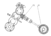
Fig. 3 is the utility model transmission assembly and colter transmission case assembly transmission sketch map.
1 tail wheel assembly wherein, 2 dashboard assemblies, 3 left and right sides rotary blade groups, 4 colter transmission case assemblies; 5 Connection Blocks, 6 left and right sidesing driving wheel assemblies, 7 support assemblies, 8 clutch cases; 9 diesel engines, 10 clutch assemblies, 11 transmission assemblies; 12 control mechanism assemblies, 13 one-level spiral bevel gears, 14 secondary spiral bevel gears.
Embodiment
Fig. 1, Fig. 2 and shown in Figure 3; Specific embodiments for the light-duty harvesting and tillage machine of the utility model; It comprises tail wheel assembly 1, dashboard assembly 2, left and right sides rotary blade group 3, colter transmission case assembly 4, Connection Block 5, left and right sidesing driving wheel assembly 6, support assembly 7, clutch case 8, diesel engine 9, clutch assembly 10, transmission assembly 11, control mechanism assembly 12, and diesel engine 9 is contained on the support assembly 7; Clutch assembly 10 is contained in transmission assembly 11 tops; Left and right sidesing driving wheel assembly 6 correspondences are contained in transmission assembly 11 both sides, and left and right sides rotary blade group 3 correspondences are contained in colter transmission case assembly 4 both sides, described driving wheel assembly 6 relative left and right sides rotary blade group 3 forerunners; Left and right sides rotary blade group 3 relative driving wheel assemblies 6 backs are ploughed; Transmission assembly 11 corresponding driving shaft hypsokinesis certain angles, transmission assembly 11 is connected with colter transmission case assembly 4 through Connection Block 5 at belly, and transmission assembly 11 forms " △ " shape robust structure with colter transmission case assembly 4.Described colter transmission case assembly 4 adopts firsts and seconds spiral bevel gears 13, the 14 rotovator left and right sides rotary blade group 3 that direct transfers.
During work; Diesel engine 9 power drive transmission assemblies 11 through clutch assembly 10, and transmission assembly 11 passes to driving wheel assembly 6 again advances, and transmission assembly 11 another roads are through colter transmission case assembly 4 rotovator left and right sides rotary blade group 3 rotary works that direct transfer; Plough behind the forerunner, realize ploughing operation.
Claims (2)
1. light-duty harvesting and tillage machine; Comprise tail wheel assembly (1), dashboard assembly (2); Left and right sides rotary blade group (3), colter transmission case assembly (4), Connection Block (5), left and right sidesing driving wheel assembly (6), support assembly (7), clutch case (8), diesel engine (9), clutch assembly (10), transmission assembly (11), control mechanism assembly (12); Diesel engine (9) is contained on the support assembly (7), and clutch assembly (10) is contained in transmission assembly (11) top, and left and right sidesing driving wheel assembly (6) correspondence is contained in transmission assembly (11) both sides; Left and right sides rotary blade group (3) correspondence is contained in colter transmission case assembly (4) both sides; It is characterized in that: described driving wheel assembly (6) is left and right sides rotary blade group (3) forerunner relatively, and left and right sides rotary blade group (3) is ploughed the corresponding driving shaft hypsokinesis of transmission assembly (11) certain angle in driving wheel assembly (6) back relatively; Transmission assembly (11) is connected with colter transmission case assembly (4) through Connection Block (5) at belly, and transmission assembly (11) forms " △ " shape robust structure with colter transmission case assembly (4).
2. light-duty harvesting and tillage machine according to claim 1 is characterized in that: described colter transmission case assembly (4) adopts two-stage spiral bevel gear (13,14) the rotovator left and right sides rotary blade group (3) that direct transfers.
Priority Applications (1)
| Application Number | Priority Date | Filing Date | Title |
|---|---|---|---|
| CN2011205359722U CN202406476U (en) | 2011-12-20 | 2011-12-20 | Lightweight cultivating machine |
Applications Claiming Priority (1)
| Application Number | Priority Date | Filing Date | Title |
|---|---|---|---|
| CN2011205359722U CN202406476U (en) | 2011-12-20 | 2011-12-20 | Lightweight cultivating machine |
Publications (1)
| Publication Number | Publication Date |
|---|---|
| CN202406476U true CN202406476U (en) | 2012-09-05 |
Family
ID=46731274
Family Applications (1)
| Application Number | Title | Priority Date | Filing Date |
|---|---|---|---|
| CN2011205359722U Expired - Fee Related CN202406476U (en) | 2011-12-20 | 2011-12-20 | Lightweight cultivating machine |
Country Status (1)
| Country | Link |
|---|---|
| CN (1) | CN202406476U (en) |
Cited By (3)
| Publication number | Priority date | Publication date | Assignee | Title |
|---|---|---|---|---|
| CN103548435A (en) * | 2013-10-25 | 2014-02-05 | 广西陆川县永发机械有限公司 | Sitting type micro tilling machine |
| CN103749011A (en) * | 2014-02-20 | 2014-04-30 | 湖南省农友机械集团有限公司 | Step tillage type rotary cultivator |
| CN106165627A (en) * | 2016-09-19 | 2016-11-30 | 福建农林大学 | Utilize paddy field pulper and the pulping process of crank and rocker mechanism arc exciting |
-
2011
- 2011-12-20 CN CN2011205359722U patent/CN202406476U/en not_active Expired - Fee Related
Cited By (4)
| Publication number | Priority date | Publication date | Assignee | Title |
|---|---|---|---|---|
| CN103548435A (en) * | 2013-10-25 | 2014-02-05 | 广西陆川县永发机械有限公司 | Sitting type micro tilling machine |
| CN103749011A (en) * | 2014-02-20 | 2014-04-30 | 湖南省农友机械集团有限公司 | Step tillage type rotary cultivator |
| CN103749011B (en) * | 2014-02-20 | 2015-11-25 | 湖南省农友机械集团有限公司 | A kind of step ploughs formula rotovator |
| CN106165627A (en) * | 2016-09-19 | 2016-11-30 | 福建农林大学 | Utilize paddy field pulper and the pulping process of crank and rocker mechanism arc exciting |
Similar Documents
| Publication | Publication Date | Title |
|---|---|---|
| CN201332574Y (en) | Sitting-tillage type multifunctional micro tillage machine | |
| CN102577667A (en) | Small-sized walking deep-tillage machine | |
| CN203435296U (en) | Light ploughing and preparing machine | |
| CN202406476U (en) | Lightweight cultivating machine | |
| CN202514247U (en) | Small walking deep ploughing machine | |
| CN201075890Y (en) | Rotary cultivating plow | |
| CN102612872B (en) | Walking type self balance mini-tiller | |
| CN201341307Y (en) | Tiller used in hilly lands | |
| CN102204429A (en) | Small-size folding steering rotary cultivator | |
| CN202496179U (en) | Self-balancing walking minitiller | |
| CN210986922U (en) | Straw full-returning soil preparation machine | |
| CN2783728Y (en) | Farm combined working machine | |
| CN201805690U (en) | Crawler cultivating and ditching machine with offset driver's seat | |
| CN2812523Y (en) | Medium-sized and small-sized tractor-plough | |
| CN204272605U (en) | A kind of automatic adjustable rotovator being suitable for hillside fields operation | |
| CN103283328B (en) | Multifunctional rotary cultivator | |
| CN2296608Y (en) | Miniature multipurpose tiller | |
| CN2836425Y (en) | Double-speed edge transmission rotary tiller | |
| CN205052086U (en) | It is light -duty from walking tiller | |
| CN200950730Y (en) | Multifunction crop straw returning-back-to-field tillage machinery matched with wheeled tractor | |
| CN205249738U (en) | Multi -functional tiller combine | |
| CN201629970U (en) | Mobile half-plow | |
| CN221510214U (en) | Miniature amphibious four-wheel-drive multifunctional rotary cultivator | |
| CN218702712U (en) | Four-wheel riding type miniature tillage equipment | |
| CN204634289U (en) | Driver plate subsoiling combined working machine |
Legal Events
| Date | Code | Title | Description |
|---|---|---|---|
| C14 | Grant of patent or utility model | ||
| GR01 | Patent grant | ||
| CF01 | Termination of patent right due to non-payment of annual fee |
Granted publication date: 20120905 Termination date: 20141220 |
|
| EXPY | Termination of patent right or utility model |