CN202294447U - Vehicle-mounted loading/unloading platform - Google Patents
Vehicle-mounted loading/unloading platform Download PDFInfo
- Publication number
- CN202294447U CN202294447U CN2011204194794U CN201120419479U CN202294447U CN 202294447 U CN202294447 U CN 202294447U CN 2011204194794 U CN2011204194794 U CN 2011204194794U CN 201120419479 U CN201120419479 U CN 201120419479U CN 202294447 U CN202294447 U CN 202294447U
- Authority
- CN
- China
- Prior art keywords
- column
- connect
- pull bar
- cab apron
- headstock
- Prior art date
- Legal status (The legal status is an assumption and is not a legal conclusion. Google has not performed a legal analysis and makes no representation as to the accuracy of the status listed.)
- Expired - Fee Related
Links
Images

Abstract
The utility model discloses a vehicle-mounted loading/unloading platform which comprises two uprights (1), a cargo plate (17), a lifting slider (18), a fixing device, a power box (7) and a lifting device, wherein guide slots are arranged on the two uprights (1); the two uprights (1) are arranged in a manner that the guide slots of the two uprights are oppositely, correspondingly and vertically arranged through the fixing device; the lifting slider (18) is arranged in the guide slots of the uprights (1); the cargo plate (17) is in clamping connection with the lifting slider (18); the uprights (1) are provided with the lifting device; the lifting device is connected with the power box (7); the lifting slider (18) is connected with the lifting device; and a power line of the power box (7) is connected with the power supply of a transport vehicle. Thus, the vehicle-mounted loading/unloading platform has the advantages of great lifting weight and convenience in operation.
Description
One, technical field
The utility model relates to a kind of escort handling platform, and especially a kind of adaptation is used for the escort handling platform of boxed truck.
Two, background technology
In carrying out goods transport, need unload goods at the enterprising luggage of transport vehicle, particularly during operation in the open air; Therefore the escort handling platform that is used for goods is an important driver's tool, existing with the car device in, mostly be easy loading and unloading such as hand push fork truck, barrel handling carrier accessory equipments; Also can only solve level land carrying problem; Can't solve the loading and unloading problem that goods and materials are got on the bus and got off, more series is equipped in formation independence, system, perfect goods and materials loading and unloading, and All-terrain Forklift and car hosit; Because cost is high, volume is big, be fit to large-scale goods and materials more than the carrying tonnage; Low load with strong power, cost height are then arranged, follow shortcomings such as constant for being used for the following material handling of 300kg; Be exactly existing domestic motor vehicles for civilian use transportation loading and unloading equipment, be commonly referred to the transportation loading and unloading haulage equipment.Except that the fork truck with maneuverability, crane, also has light handling carrier like armstrong's patent formula forklift, manual hydraulic tray transport cart, scissor lift table, oil drum transportation fork-truck etc.Characteristics such as that these motor vehicles for civilian use transportation loading and unloadings equipment has is simple in structure, light practicality; Can be used for short-range carrying of small-sized object or elevating; To reduce labor intensity; But they are not suitable for using under the field condition, and carrying weight generally is no more than 200kg, the needs that can not to satisfy present field work handling capacity be 300kg.
Three, summary of the invention
In order to overcome above-mentioned technical disadvantages, the purpose of the utility model provides a kind of escort handling platform, so lifting weight is big, and is easy to operate.
For achieving the above object; The technical scheme that the utility model is taked is: include column, goods plate, lifting slider, anchor fitting, headstock and jacking system, column is provided with guide groove, and column is set to two and be set to make through anchor fitting that its guide groove is corresponding in opposite directions to be arranged vertically; Lifting slider is arranged in the guide groove of column; The goods plate is set to connect with the lifting slider plug-in, and column is provided with jacking system, and jacking system is set to connect with headstock; Lifting slider is set to connect with jacking system, and the power line of headstock is set to be connected with the power supply of transport trolley.
Vertical two columns, be connected the goods plate with lifting slider, lifting slider is connected with headstock through jacking system; Be put into goods on the goods plate, start headstock, make jacking system work; Thereby in the container of transport trolley, include column, goods plate, lifting slider, anchor fitting, headstock and jacking system to freight lifting owing to designed, the power supply that can use transport trolley is as power; In container, so lifting weight is big freight lifting, and is easy to operate.
The utility model has designed; Jacking system is set to include transmission shaft; Jacking system is arranged on two ends up and down in the guide groove of column and is respectively arranged with sprocket wheel, goes up that lower sprocket is provided with chain and lifting slider is set to connect with chain, and lower sprocket is set to connect with headstock through transmission shaft.
The utility model has designed, and anchor fitting is set to include cab apron support and pull bar, is provided with protruding pin in the lower end of column; Pull bar is provided with cotter-pin hold, and pull bar is set to two and be separately positioned on the both sides of column, and the protruding pin of column is arranged in the cotter-pin hold of pull bar; Column is set to connect with pull bar through bolt, is provided with notch in the both sides of cab apron support, and two columns are separately positioned in the notch of cab apron support; Column is set to connect with the cab apron support through bolt
The utility model has designed, and also includes pull bar, and an end of pull bar is set to that lateral surface at pull bar connects with pull bar, the other end is set to connects with the headstock shell.
The utility model has designed, and also includes cab apron and plinth plate, and cab apron is set to connect with cab apron support radial type, and cab apron is set to connect with the cargo floor contact of transport trolley, and the plinth plate is arranged on the side of column.
Four, description of drawings
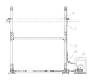
Fig. 1 is the scheme drawing of the utility model:
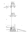
Fig. 2 is the birds-eye view of Fig. 1:
Fig. 3 is the right elevation of Fig. 1.
Five, the specific embodiment
Accompanying drawing is an embodiment of the utility model, specifies present embodiment in conjunction with accompanying drawing, includes column 1, cab apron support 22, goods plate 17, lifting slider 18, pull bar 3, headstock 7, pull bar 16, cab apron 20, plinth plate 23, transmission shaft 2; Column 1 is provided with guide groove, is provided with protruding pin in the lower end of column 1, and pull bar 3 is provided with cotter-pin hold; Column 1 is set to two and be set to that its guide groove is corresponding in opposite directions to be arranged, and pull bar 3 is set to two and be separately positioned on the both sides of column 1, and the protruding pin of column 1 is arranged in the cotter-pin hold of pull bar 3; Column 1 is set to connect with pull bar 3 through bolt, is provided with notch in the both sides of cab apron support 22, and two columns 1 are separately positioned in the notch of cab apron support 22; Column 1 is set to connect with cab apron support 22 through bolt; Lifting slider 18 is arranged in the guide groove of column 1, and goods plate 17 is set to connect with lifting slider 18 plug-ins, and the two ends up and down in the guide groove of column 1 are respectively arranged with sprocket wheel; Last lower sprocket is provided with chain; Lifting slider 18 is set to connect with chain, and lower sprocket is set to connect with headstock 7 through transmission shaft 2, and an end of pull bar 16 is set to that lateral surface at pull bar 3 connects with pull bar 3, the other end is set to connects with headstock 7 shells; Cab apron 20 is set to connect with cab apron support 22 radial types; Cab apron 20 is set to connect with the cargo floor contact of transport trolley, and plinth plate 23 is arranged on the side of column 1, and the power line of headstock 7 is set to be connected with the power supply of transport trolley.Vertical two columns 1, be connected goods plate 17 with lifting slider 18, lifting slider 18 is connected with headstock 7 through the sprocket wheel link chain mechanism; Be put into goods on the goods plate 17; Start headstock 7, make the work of sprocket wheel link chain mechanism, thus freight lifting in the container of transport trolley.
In the present embodiment; Employing is supported in ground by 2 root post bottom support brackets; The bottom is formed framework with two pull bar transverse splicings, top through cab apron support located lateral, the big railway carriage or compartment of cab apron and transport trolley trailing edge overlap joint, and DC machine and reductor aggregate erection are on same support; Connect the power path of taking turns with this side chain through output shaft; Through transmission shaft power is passed to the opposite side sprocket wheel again, the chain two ends are walked around the slide block of lower sprocket and the inboard lifting mechanism of two columns respectively and are fixed, and goods platform overlap joint is realized up-and-down movement through chain on the slide block of lifting mechanism; Cab apron places the big railway carriage or compartment of transport trolley trailing edge, and is hinged with the cab apron support; The plinth plate places ground, and with column bottom support bracket overlap joint, the plane is concordant on the upper limb on inclined-plane and the goods platform; Motor power-supply wire is connected with the transport trolley power-supply system, and control capsule is hung on the heel post.
The characteristics of the utlity model has down:
1, owing to designed and included column 1, goods plate 17, lifting slider 18, anchor fitting, headstock 7 and jacking system, the power supply that can use transport trolley is as power, in container, so lifting weight is big freight lifting, and is easy to operate.
2, volume is little, curb mass is light, simple in structure, be convenient to carry with car; Adopt sectional construction, launch and remove receive simple and easy to do, the compartment Occupation efficiency is little, efficiency-cost ratio is high, external form is succinctly attractive in appearance, be suitable for the open-air loading and unloading work field operations state under.
3, do not change vehicle structure, do not influence the automotive technology performance, can adapt to different transportation vehicles, have stronger commonality; The electric power that utilizes alternator for vehicle to provide drives the loading/unloading platform operation, and power is taken a kind of easily novel escort handling platform.
So 4 vehicular transport units load and unload in the open air or the way in when having bad luck small-sized relatively goods and materials, can only lean on manual work, restricted the raising that the highway troop-carrying ensure usefulness.
The utility model place comformability is strong, can be under the field operations situation, and the loading and unloading operation task is accomplished on relative complex ground.。Have volume little, in light weight, simple in structure, be easy to assembling, be convenient to dismounting, characteristics such as easy to use, carrying convenience, transportation property are good, efficiency-cost ratio height.The goods and materials unloading of fall carrying and arriving behind the tactical logistics disposition region in transit goods and materials under the field condition provides sound assurance.
In escort handling platform technology field; Every column 1 that includes is provided with guide groove; Column 1 is set to two and be set to make through anchor fitting that its guide groove is corresponding in opposite directions to be arranged vertically; Lifting slider 18 is arranged in the guide groove of column 1; Goods plate 17 is set to connect with lifting slider 18 plug-ins, and column 1 is provided with jacking system, and jacking system is set to connect with headstock 7; Lifting slider 18 is set to connect with jacking system, and the power line of headstock 7 is set to power supply bonded assembly technology contents with transport trolley all in the protection domain of the utility model.
Claims (5)
1. escort handling platform; It is characterized in that: include column (1), goods plate (17), lifting slider (18), anchor fitting, headstock (7) and jacking system; Column (1) is provided with guide groove; Column (1) is set to two and be set to make through anchor fitting that its guide groove is corresponding in opposite directions to be arranged vertically; Lifting slider (18) is arranged in the guide groove of column (1); Goods plate (17) is set to connect with lifting slider (18) plug-in, and column (1) is provided with jacking system, and jacking system is set to connect with headstock (7); Lifting slider (18) is set to connect with jacking system, and the power line of headstock (7) is set to be connected with the power supply of transport trolley.
2. escort handling platform according to claim 1; It is characterized in that: jacking system is set to include transmission shaft (2); Jacking system is arranged on two ends up and down in the guide groove of column (1) and is respectively arranged with sprocket wheel, goes up that lower sprocket is provided with chain and lifting slider (18) is set to connect with chain, and lower sprocket is set to connect with headstock (7) through transmission shaft (2).
3. escort handling platform according to claim 1; It is characterized in that: anchor fitting is set to include cab apron support (22) and pull bar (3); Lower end at column (1) is provided with protruding pin; Pull bar (3) is provided with cotter-pin hold, and pull bar (3) is set to two and be separately positioned on the both sides of column (1), and the protruding pin of column (1) is arranged in the cotter-pin hold of pull bar (3); Column (1) is set to connect with pull bar (3) through bolt; Both sides at cab apron support (22) are provided with notch, and two columns (1) are separately positioned in the notch of cab apron support (22), and column (1) is set to connect with cab apron support (22) through bolt.
4. according to claim 1,2 or 3 described escort handling platforms; It is characterized in that: also include pull bar (16), an end of pull bar (16) is set to that lateral surface at pull bar (3) connects with pull bar (3), the other end is set to connects with headstock (7) shell.
5. according to claim 1,2 or 3 described escort handling platforms; It is characterized in that: also include cab apron (20) and plinth plate (23); Cab apron (20) is set to connect with cab apron support (22) radial type; Cab apron (20) is set to connect with the cargo floor contact of transport trolley, and plinth plate (23) is arranged on the side of column (1).
Priority Applications (1)
| Application Number | Priority Date | Filing Date | Title |
|---|---|---|---|
| CN2011204194794U CN202294447U (en) | 2011-10-29 | 2011-10-29 | Vehicle-mounted loading/unloading platform |
Applications Claiming Priority (1)
| Application Number | Priority Date | Filing Date | Title |
|---|---|---|---|
| CN2011204194794U CN202294447U (en) | 2011-10-29 | 2011-10-29 | Vehicle-mounted loading/unloading platform |
Publications (1)
| Publication Number | Publication Date |
|---|---|
| CN202294447U true CN202294447U (en) | 2012-07-04 |
Family
ID=46363403
Family Applications (1)
| Application Number | Title | Priority Date | Filing Date |
|---|---|---|---|
| CN2011204194794U Expired - Fee Related CN202294447U (en) | 2011-10-29 | 2011-10-29 | Vehicle-mounted loading/unloading platform |
Country Status (1)
| Country | Link |
|---|---|
| CN (1) | CN202294447U (en) |
Cited By (2)
| Publication number | Priority date | Publication date | Assignee | Title |
|---|---|---|---|---|
| CN103568918A (en) * | 2013-08-01 | 2014-02-12 | 王延斌 | Automatically loaded carriage |
| CN104670922A (en) * | 2015-02-13 | 2015-06-03 | 杨昌懿 | Rolling wheel powerless goods self-elevating loading device and loading method |
-
2011
- 2011-10-29 CN CN2011204194794U patent/CN202294447U/en not_active Expired - Fee Related
Cited By (3)
| Publication number | Priority date | Publication date | Assignee | Title |
|---|---|---|---|---|
| CN103568918A (en) * | 2013-08-01 | 2014-02-12 | 王延斌 | Automatically loaded carriage |
| CN103568918B (en) * | 2013-08-01 | 2016-06-01 | 王延斌 | A kind of automatic loading and unloading compartment |
| CN104670922A (en) * | 2015-02-13 | 2015-06-03 | 杨昌懿 | Rolling wheel powerless goods self-elevating loading device and loading method |
Similar Documents
| Publication | Publication Date | Title |
|---|---|---|
| JP5699260B2 (en) | Large transport vehicles, especially self-driving large transport vehicles for ISO containers | |
| US10457534B2 (en) | Heavy-duty lift truck | |
| US20140017046A1 (en) | Straddle carrier device comprising electric drives | |
| CN201376519Y (en) | Full-rotation suspending arm-type container automatic loading and unloading engineering truck | |
| US20140017045A1 (en) | Straddle carrier device comprising electric drives | |
| CN202130500U (en) | Quick-release cargo truck | |
| CN201713270U (en) | Fork truck used for loading, unloading and transporting bagged miscellaneous goods | |
| CN105197843A (en) | Semi-electric piling car | |
| CN205933106U (en) | Fork truck of collapsible prong | |
| CN103496639A (en) | Overall loading and unloading vehicle based on slidable vehicle -mounted crane | |
| CN105883673A (en) | Rapid maneuvering loading and unloading transport cart for containers | |
| CN101208253A (en) | Trailer for automobile | |
| CN104071585B (en) | A kind of bilateral container self-loading and unloading vehicle | |
| CN210912642U (en) | Wing opening type van-type transport vehicle | |
| CN201646505U (en) | Cargo handling device for van truck | |
| CN103522932B (en) | Car transporter | |
| CN202294447U (en) | Vehicle-mounted loading/unloading platform | |
| CN201148145Y (en) | Pulling arm type free handling device of wagon | |
| CN100384714C (en) | Vehicle-mounted carrying robot with folding frame | |
| CN201506574U (en) | Car packaging recyclable goods shelf | |
| CN205668919U (en) | A kind of transporting container dolly | |
| CN201553068U (en) | Multifunctional transport vehicle with function of auto loading and unloading | |
| CN214456598U (en) | Anti-toppling forklift | |
| CN100999303A (en) | Suspension type folding fork truck | |
| CN204778656U (en) | Pile portal system on high car |
Legal Events
| Date | Code | Title | Description |
|---|---|---|---|
| C14 | Grant of patent or utility model | ||
| GR01 | Patent grant | ||
| C17 | Cessation of patent right | ||
| CF01 | Termination of patent right due to non-payment of annual fee |
Granted publication date: 20120704 Termination date: 20131029 |