CN202283816U - Liquid containing container, liquid spraying system and liquid feed system - Google Patents
Liquid containing container, liquid spraying system and liquid feed system Download PDFInfo
- Publication number
- CN202283816U CN202283816U CN2011203317778U CN201120331777U CN202283816U CN 202283816 U CN202283816 U CN 202283816U CN 2011203317778 U CN2011203317778 U CN 2011203317778U CN 201120331777 U CN201120331777 U CN 201120331777U CN 202283816 U CN202283816 U CN 202283816U
- Authority
- CN
- China
- Prior art keywords
- liquid
- mentioned
- aforesaid liquid
- ink
- wall portion
- Prior art date
- Legal status (The legal status is an assumption and is not a legal conclusion. Google has not performed a legal analysis and makes no representation as to the accuracy of the status listed.)
- Withdrawn - After Issue
Links
Images


Abstract
The utility model relates to a liquid containing container, a liquid spraying system and a liquid feed system, which aim at providing technology for reducing harmful situations in the liquid containing container with a liquid injection port. The liquid containing container comprises a liquid containing chamber, the liquid injection port, a bolt component, an atmosphere open flow path and a deriving portion, wherein the liquid containing chambers are formed by a plurality of wall portions and used for containing liquid, the liquid injection port is used for injecting the liquid in the liquid containing container, one end portion of the liquid injection port opens outwards, and the other end portion of the liquid injection port opens in the liquid containing chamber. Under a using state, a second flow path including a liquid lateral opening and an air lateral opening is located at the position lower than the other end portion of the liquid injection port. An injection state of the liquid containing chamber is different from the using state and is a state of the position where the air lateral opening is located at the position higher than the other end portion of the liquid injection port.
Description
Technical field
The utility model relates to liquid accommodating container, possesses the liquid injection system and the liquid-supplying system of liquid accommodating container.
Background technology
As the printer of an example of liquid injection apparatus from record head towards record object (for example printing) ejection ink and printing.As the providing ink technology of supplying with ink towards record head, known have a technology (for example patent documentation 1) of supplying with ink from the print cartridge in the outside that is configured in printer through flexible pipe towards record head.Print cartridge possesses liquid injection port (ink is filled mouth), and the person of utilization can easily inject (replenishing) ink from liquid injection port.
Patent documentation 1: TOHKEMY 2005-219483 communique
Replenish ink inner, and supply with under the situation of ink, various unfavorable conditions take place sometimes from print cartridge towards printer from liquid injection port towards print cartridge.For example, print cartridge possesses the consumption that is used to be accompanied by ink and air is imported the inner atmosphere of print cartridge opens wide stream.When under the situation of the inner filling ink of print cartridge, exist ink to open wide stream and be spilled over to outside situation from atmosphere.And for print cartridge, for the record head towards printer is stably supplied with ink, the liquid level (atmosphere contact liquid level) of preferably that print cartridge is inner ink that is the ink that contacts with atmosphere maintains the altitude range of regulation with respect to record head.For example, spill from record head for fear of ink, atmosphere contact liquid level is maintained at below the height that record head is positioned at.Yet present dynasty's print cartridge filling ink and begin once more from print cartridge towards record head is supplied with under the situation of providing ink operation of ink, exists atmosphere contact liquid level not to be maintained at the altitude range of regulation, can't stably supply with the situation of ink from print cartridge towards record head.For example, exist atmosphere contact liquid level to be positioned at the position of leaning on the top than record head, the situation that causes ink to spill because of pressure (hydraulic pressure) from record head from print cartridge.
Aforesaid problem is not limited to print cartridge, is to take in the liquid accommodating container of the liquid that liquid injection apparatus sprays, promptly possess and be used for the common problem of liquid accommodating container of injecting the liquid injection port of liquid towards inner.
The utility model content
Therefore, the purpose of the utility model is, in possessing the liquid accommodating container of liquid injection port, a kind of technology that alleviates the generation of unfavorable condition is provided.
The utility model is accomplished at least a portion that solves above-mentioned problem, can realize as following embodiment or application examples.
Application examples 1
A kind of liquid accommodating container is characterized in that,
This liquid accommodating container is used for to the liquid injection apparatus feed fluid,
The aforesaid liquid accommodating container possesses:
The liquid accommodating chamber, this liquid accommodating chamber is formed by a plurality of wall portion, is used to take in aforesaid liquid;
Liquid injection port, this liquid injection port are used for injecting aforesaid liquid to above-mentioned liquid accommodating chamber, and an end is open facing outward, and the other end is at aforesaid liquid receiving room inner opening;
Latch, this latch are used for shutoff aforesaid liquid inlet;
Atmosphere opens wide stream, and this atmosphere opens wide stream and is used for air outside to the indoor importing of above-mentioned liquid accommodating; And
Leading-out portion, this leading-out portion are used for supplying with to above-mentioned liquid injection apparatus the aforesaid liquid of aforesaid liquid receiving room,
Above-mentioned atmosphere opens wide stream to be possessed:
The air receiving room, this air receiving room has the volume of regulation;
First stream, this first stream makes above-mentioned air receiving room and external communications; And
Second stream; One end of this second stream that is air side opening are at above-mentioned air receiving room inner opening; The other end that is hydraulic fluid side opening are at aforesaid liquid receiving room inner opening; The aforesaid liquid receiving room is communicated with above-mentioned air receiving room, and this second stream keeps aforesaid liquid through forming meniscus
Under the user mode of the liquid accommodating container of horizontal direction opening, comprise above-mentioned second stream of aforesaid liquid side opening and above-mentioned air side opening at the aforesaid liquid inlet, be positioned at the position of leaning on the below than above-mentioned the other end of aforesaid liquid inlet,
Under the injection state of aforesaid liquid inlet opening above the vertical, above-mentioned air side opening is positioned at the position of leaning on the top than above-mentioned the other end of aforesaid liquid inlet.
The liquid accommodating container of being put down in writing according to application examples 1 owing to be positioned at the position above leaning on than the other end of liquid injection port at the state of injection air side opening, therefore can reduce the possibility that liquid when injecting liquid is imported into the air receiving room.Thus, can reduce liquid from being communicated with air receiving room and outside first stream portion's possibility of overflowing outwardly.And, owing to can reduce the possibility that liquid is imported into the air receiving room, therefore just injecting liquid after under user mode, also can the liquid level of the liquid accommodating container inside that contacts with atmosphere be maintained the altitude range of regulation.In addition, in user mode, be positioned at the position of leaning on the below than liquid injection port, therefore can be formed with meniscus for a long time, can keep the height of the liquid level that contacts with atmosphere constant for a long time owing to be formed with second stream of meniscus.
Application examples 2
The liquid accommodating container of being put down in writing according to application examples 1, wherein,
When from aforesaid liquid inlet court above-mentioned liquid accommodating chamber injection aforesaid liquid; In order to make the person of utilization can state be changed over above-mentioned injection state from above-mentioned user mode; An above-mentioned end of aforesaid liquid inlet with under the above-mentioned user mode towards the horizontal direction opening, under the above-mentioned injection state on the vertical mode of direction opening, be arranged at any of above-mentioned a plurality of wall portion.
Usually, inject from liquid injection port towards the liquid accommodating chamber under the situation of liquid the person of utilization, under the situation of an end of liquid injection port direction opening on the vertical, the person of utilization injects the liquid accommodating chamber with liquid more easily.Therefore, the liquid accommodating container according to application examples 2 is put down in writing when the person of utilization injects liquid from liquid injection port towards the liquid accommodating chamber, can impel the person of utilization to make the state of liquid accommodating container become the injection state.Thus, can reduce the unfavorable condition that produces when injecting liquid.
Application examples 3
The liquid accommodating container of being put down in writing according to application examples 2, wherein,
Above-mentioned a plurality of wall portion comprises: become a plurality of wall portions that are provided with that erect that erect the state of setting at the above-mentioned user mode face that is provided with set with respect to the aforesaid liquid accommodating container,
The aforesaid liquid inlet is arranged at above-mentioned a plurality of airside wall portion in the wall portion, that be positioned at the side that above-mentioned air receiving room disposed that is provided with that erects.
According to the liquid accommodating container that application examples 3 is put down in writing, can easily be formed on user mode one end towards the horizontal direction opening, in injection state one end on the vertical liquid injection port of direction opening.
Application examples 4
According to each the described liquid accommodating container in the application examples 1 to 3, wherein,
The aforesaid liquid accommodating container also possesses:
Lower limit portion; This lower limit portion be arranged in the above-mentioned a plurality of wall portion can be from the first wall portion of outside Visual Confirmation; Under above-mentioned user mode, this lower limit portion of Visual Confirmation is able to be consumed and the amount of the aforesaid liquid of aforesaid liquid receiving room reaches the situation of first threshold from the aforesaid liquid of outside identification aforesaid liquid receiving room; And
Upper limit portion; This upper limit portion is arranged at different with above-mentioned first wall portion in the above-mentioned a plurality of wall portion and can be from the second wall portion of outside Visual Confirmation; Under above-mentioned injection state; This upper limit portion of Visual Confirmation is able to from outside identification from the aforesaid liquid inlet to inject aforesaid liquid towards above-mentioned liquid accommodating chamber and the amount of the aforesaid liquid of aforesaid liquid receiving room reaches the situation of second threshold value
Above-mentioned first wall portion is that the face that is provided with set with respect to the aforesaid liquid accommodating container under above-mentioned user mode is the wall portion that erects the state of setting,
The above-mentioned second wall portion is that the face that is provided with set with respect to the aforesaid liquid accommodating container under above-mentioned injection state is the wall portion that erects the state of setting.
According to the liquid accommodating container that application examples 4 is put down in writing, owing to be respectively arranged with lower limit portion and upper limit portion, therefore, under each state, the person of utilization can both easily confirm the amount of the liquid of liquid accommodating chamber.
Application examples 5
The liquid accommodating container of being put down in writing according to application examples 4, wherein,
Above-mentioned lower limit portion is the linearity of level in above-mentioned user mode,
Above-mentioned upper limit portion is the linearity of level at above-mentioned injection state.
According to the liquid accommodating container that application examples 5 is put down in writing, the person of utilization can be at each state through liquid level and lower limit portion or upper limit portion are compared and more easily confirm the amount of the liquid of liquid accommodating chamber.
Application examples 6
A kind of liquid injection system is characterized in that,
The aforesaid liquid spraying system possesses:
The described liquid accommodating container of in the application examples 1 to 5 each;
Liquid injection apparatus, this liquid injection apparatus have the shower nozzle that is used for spraying towards object aforesaid liquid; And
Runner pipe, this runner pipe connects the above-mentioned leading-out portion and the aforesaid liquid injection apparatus of aforesaid liquid accommodating container, makes the aforesaid liquid that is accommodated in the aforesaid liquid receiving room flow to the aforesaid liquid injection apparatus.
Liquid injection system according to application examples 6 is put down in writing even if under the user mode after just injecting liquid, also can maintain the altitude range that distance is provided with the face regulation by the liquid level that contacts with atmosphere that liquid accommodating container is inner.Thus, the difference of height of the liquid level that can shower nozzle be contacted with atmosphere maintains the scope of regulation, can be from shower nozzle atomizing of liquids stably.
Application examples 7
A kind of liquid-supplying system is characterized in that,
The aforesaid liquid feed system possesses:
The described liquid accommodating container of in the application examples 1 to 5 each;
Odd-side, this odd-side have liquid flow road and liquid-receiver portion, flow on the liquid flow road to the liquid that is used for towards the shower nozzle of object injection aforesaid liquid is supplied with; And
Runner pipe, this runner pipe connects the above-mentioned leading-out portion of aforesaid liquid accommodating container and the aforesaid liquid receptacle of above-mentioned odd-side, makes the aforesaid liquid of aforesaid liquid receiving room be passed to above-mentioned odd-side.
Liquid-supplying system according to application examples 7 is put down in writing even if under the user mode after just injecting liquid, also can maintain the altitude range that distance is provided with the face regulation by the liquid level that contacts with atmosphere that liquid accommodating container is inner.Thus, the difference of height of the liquid level that can shower nozzle be contacted with atmosphere maintains the scope of regulation, can be from shower nozzle atomizing of liquids stably.
In addition; The utility model can be realized with various embodiments; Except above-mentioned liquid accommodating container, possess the liquid injection system of liquid injection apparatus and liquid accommodating container, can also be with the manufacturing approach of above-mentioned liquid accommodating container, use the variety of ways such as liquid jet method of above-mentioned liquid injection system to realize.
Description of drawings
Fig. 1 is used for the figure that the liquid injection system 1 to embodiment describes.
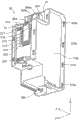
Fig. 2 is the stereoscopic figure of box unit 50.
Fig. 3 is used for second figure that the liquid injection system 1 to embodiment describes.
Fig. 4 is schematically illustrated from the figure of atmosphere introducing port 317 up to the path of liquid leading-out portion 306.
Fig. 5 is used for the figure that the principle to providing ink describes.
Fig. 6 is the first stereoscopic figure of print cartridge 30.
Fig. 7 is the second stereoscopic figure of print cartridge 30.
Fig. 8 is the 3rd stereoscopic figure of print cartridge 30.
Fig. 9 is the figure that the few state of the ink surplus of liquid accommodating chamber 340 is shown.
Figure 10 is used for the ink that injects ink towards print cartridge 30 is injected the figure that operation describes.
Figure 11 is used for the figure that the state to ink describes.
Figure 12 is used for the figure that the liquid injection system 1k to comparative example describes.
Label declaration
1: liquid injection system; 1k: liquid injection system; 10: housing; 12: ink-jet printer (printer); 13: the paper supply unit; 14: paper discharge portion; 16: balladeur train; 16a: ink supply needle; 17: record head; 20: odd-side; 20Bk: odd-side; 20Ma: odd-side; 20Cn: odd-side; 20Yw: odd-side; 24: flexible pipe; 30: liquid accommodating container (print cartridge); 32: toner cartridge main body; 34: the first film; 50: box unit; 54: the end face housing; 56: the first side housings; 58: the second side housings; 202: liquid-receiver portion; 204: the ink storeroom; 206: filter; 208: the ink road of flowing; 300: atmosphere opens wide stream; 302: latch; 303: link parts; 304: liquid injection port; 304k: liquid injection port; 304m: bottom (the other end); 304p: upper end (end); 306: the liquid leading-out portion; 310: the first streams; 312: gas-liquid separation chamber; 314: be communicated with stream; 316: sheet component; 317: the atmosphere introducing port; 318: the atmosphere open ports; 320: be communicated with stream; 322: the second films; 324: jut; 325a: hole portion; 328: chimeric unit; 330: the air receiving room; 340: the liquid accommodating chamber; 342: divide wall portion; 345: the liquid maintaining part; 349: liquid outlet portion; 350: the second streams (interconnecting part); 351: the air side opening; 352: the hydraulic fluid side opening; 362: rib; 370: perforated wall portion (open side); 370b: opposed walls portion; 370c: connecting wall portion; 370c1: first wall portion; 370c2: the second wall portion; 370c3: airside wall portion; 980: replenish and use container; G: air (bubble); LA: atmosphere contact liquid level; Sf: horizontal plane (face is set); LM1: lower limit line; LM2: upper limit line.
The specific embodiment
Secondly, describe according to the embodiment of following order the utility model.
A. embodiment and comparative example:
B. variation:
A. embodiment and comparative example:
A-1. the structure of liquid injection system:
Fig. 1 is used for the figure that the liquid injection system 1 to embodiment describes.Fig. 1 (A) is the first stereoscopic figure of liquid injection system 1.Fig. 1 (B) is the second stereoscopic figure of liquid injection system 1, is the figure of liquid accommodating container 30 that the embodiment of the utility model is shown.In addition, in Fig. 1, mutually orthogonal XYZ axle is shown in order to confirm direction.In addition, about after this figure mutually orthogonal XYZ axle is shown as required also.
Shown in Fig. 1 (A), liquid injection system 1 possesses: as the ink-jet printer 12 (also only being called " printer 12 ") of liquid injection apparatus; And box unit 50.Printer 12 possesses: paper supply unit 13, paper discharge portion 14,16 and 4 odd-sides 20 of balladeur train (odd-side department of assembly).4 odd-sides 20 are taken in the different ink of color.Particularly, 4 odd-sides 20 are: take in the odd-side 20Bk of black ink, take in the odd-side 20Cn of cyan, take in the odd-side 20Ma of magenta ink, and the odd-side 20Yw that takes in yellow ink.4 odd-sides are equipped on balladeur train 16.
The printing that is placed in paper supply unit 13 is transported to printer 12 inside, and the printing after the printing is discharged from from paper discharge portion 14.
4 print cartridges 30 are taken in the corresponding ink of being taken in 4 odd-sides 20 of color.That is, 4 print cartridges 30 are taken in black ink, cyan, magenta ink and yellow ink respectively.Each print cartridge 30 can be confirmed the state of ink through the part of regulation from the outside.In addition, print cartridge 30 can be taken in the ink of the more amount of amount of being taken in than odd-side 20.
The print cartridge 30 of taking in versicolor ink connects through the odd-side 20 of flexible pipe (pipe) 24 with the ink that is used to take in corresponding color.Flexible pipe 24 has flexible parts by synthetic rubber etc. and forms.When thereby the ink that sprays ink odd-side 20 from record head was consumed, the ink of print cartridge 30 was fed into odd-side 20 via flexible pipe 24.Thus, liquid injection system 1 can not have the lasting continuously printing in interrupt action ground for a long time.In addition, also odd-side 30 can be set, but directly supply with ink from print cartridge 30 towards record head via flexible pipe 24.
Fig. 2 is the stereoscopic figure of box unit 50.In Fig. 2, omitted the diagram of end face housing 54 and bottom surface housing.For box unit 50, under the user mode towards printer 12 supply inks the time, Z-direction is a vertical, and Z axle negative direction is the vertical lower direction.Each print cartridge 30 has and is used for chimeric unit 328 chimeric with adjacent print cartridge 30 and that be integrally formed.Chimeric unit 328 possesses the jut 324 of 325a of hole portion and overshooting shape.Through the chimeric jut 324 that another adjacent print cartridge 30 is arranged among the 325a of hole portion that makes 1 print cartridge 30, adjacent print cartridge 30 assembles each other and is one.In addition, jut 324 can the 325a of portion unloads from the hole by the external force quilt, can easily the print cartridge that becomes one 30 be decomposed.Thus, box unit 50 can be according to the quantity of employed ink color in the printer 12, specification and is easily changed the configurable number (range upon range of number) of print cartridge 30.
And print cartridge 30 possesses atmosphere introducing port 317.The atmosphere that atmosphere introducing port 317 is stated after being opens wide in the both ends of stream, and is inner and be provided with in order atmosphere outside to be imported print cartridge 30.When from the liquid leading-out portion (not shown) of print cartridge 30 via flexible pipe when printer 12 is supplied with inks, atmosphere outside is imported into print cartridge 30 inside via atmosphere introducing port 317.
Fig. 3 is used for second figure that the liquid injection system 1 to embodiment describes.Fig. 3 (A) is the figure of the liquid injection system 1 when print cartridge 30 being shown being in user mode (liquid injection port 304 is towards the state of horizontal direction opening).Fig. 3 (B) is the figure of the liquid injection system 1 when print cartridge 30 being shown being in state when injecting ink and injecting state.In addition, liquid injection system 1 is arranged at horizontal plane with X axle and Y axle defined and promptly face is set and is used.
Shown in Fig. 3 (A), print cartridge 30 is arranged to, and under user mode (liquid injection port 304 is towards the state of horizontal direction opening), the 370c1 of wall portion (first wall portion) of a part can be from the state of outside Visual Confirmation.Under user mode (liquid injection port 304 is towards the state of horizontal direction opening), the 370c1 of first wall portion is the wall portion that erects the state of setting with respect to the face of setting.That is, under user mode, the 370c1 of first wall portion is the wall portion of extending towards the top from the below of print cartridge 30.In the present embodiment, the 370c1 of first wall portion is with respect to the wall portion that the face approximate vertical is set.In addition, under the injection state of print cartridge 30 (state of liquid injection port 304 direction opening on the vertical), the 370c1 of first wall portion constitutes the bottom surface of print cartridge 30.
Be provided with lower limit line LM1 at the 370c1 of first wall portion as lower limit portion.Lower limit line LM1 is the linearity of level under user mode.The situation that lower limit line LM1 is consumed for ink inner under the user mode that is identified in print cartridge 30 and then inner ink reaches first threshold is provided with.Under near the liquid level of ink reaches first threshold the situation, the person of utilization is towards the print cartridge 30 inner inks that replenish.
Shown in Fig. 3 (B), under the situation of print cartridge 30 inner injection (replenishing) inks, the person of utilization makes the state of print cartridge 30 be varied to the injection state of liquid injection port 304 towards vertical top (Z axle positive direction) opening from user mode.And then, open end face housing 54.The person of utilization takes off latch 302 from liquid injection port 304, and injects ink from liquid injection port 304 towards inside.
Here, through opening end face housing 54, can be from the outside Visual Confirmation second wall portion 370c2 different with the 370c1 of first wall portion.Second 370c2 of wall portion is the wall portion that erects the state of setting with respect to the face of setting.That is, under user mode (liquid injection port 304 is towards the state of horizontal direction opening), second 370c2 of wall portion is the wall portion of extending towards the top from the below.In the present embodiment, second 370c2 of wall portion is with respect to the wall portion that the face approximate vertical is set under the injection state.
Be provided with upper limit line LM2 at second 370c2 of wall portion as upper limit portion.Upper limit line LM2 is the linearity of level under the injection state.Upper limit line LM2 is in order to be provided with when the situation that reaches second threshold value from the ink of liquid injection port 304 liquid accommodating of identification when injecting inks chambers 340 340 towards the liquid accommodating chamber under the injection attitude at print cartridge.
The person of utilization towards the inside of print cartridge 30 inject (replenishing) ink near ink level reaches upper limit line LM2 till.After carrying out the replenishing of ink, make the state variation of print cartridge 30 become the user mode shown in Fig. 3 (A) (liquid injection port 304 is towards the state of horizontal direction opening).Like this, the person of utilization can easily confirm the amount of the ink of print cartridge 30 inside under each state.
A-2. the summary of print cartridge 30:
Before the detailed structure to print cartridge 30 describes,, schematically the path from atmosphere introducing port 317 to liquid leading-out portion 306 is described with reference to Fig. 4 for the ease of understanding.Fig. 4 is the figure in schematically illustrated path from atmosphere introducing port 317 to liquid leading-out portion 306.
Path from atmosphere introducing port 317 to liquid leading-out portion 306 roughly is divided into atmosphere and opens wide stream 300 and liquid accommodating chamber 340.Atmosphere opens wide stream 300 to begin from the upper reaches successively to be made up of first stream 310, air receiving room 330, second stream 350 (being also referred to as interconnecting part 350).
One end of first stream 310 be atmosphere open ports 318 at air receiving room 330 inner openings, the other end is that atmosphere introducing port 317 is open facing outward, makes air receiving room 330 and external communications thus.First stream 310 has the stream 320 of connection, gas-liquid separation chamber 312 and is communicated with stream 314.An end that is communicated with stream 320 is communicated with atmosphere introducing port 317, and the other end is communicated with gas-liquid separation chamber 312.A part that is communicated with stream 320 is elongated stream, and the moisture that inhibition is stored in the ink of liquid accommodating chamber 340 opens wide the situation that stream 300 evaporates because of diffusion from atmosphere.During downstream, dispose sheet component (thin film component) 316 from the upper reaches in gas-liquid separation chamber 312.The character that this sheet component 316 has the gas permeation of making and liquid is seen through.Open wide stream 300 midway through this sheet component 316 being configured in atmosphere, can suppress the ink that 340 adverse currents are come from the liquid accommodating chamber and flow into the situation of leaning on the position of upstream side than sheet component 316.In addition, in a single day this sheet component 316 is soaked by ink, then can lose the original function as gas-liquid separation membrane, and existence can't make the situation of air permeation.
Being communicated with stream 314 makes gas-liquid separation chamber 312 be communicated with air receiving room 330.Here, an end of connection stream 314 is atmosphere open ports 318.
The flow path cross sectional area of second stream of stating behind the flow path cross sectional area ratio of air receiving room 330 350 is big, and the volume with regulation.Thus, can store the ink that 340 adverse currents are come from the liquid accommodating chamber, can suppress ink and flow into the situation of leaning on the position of upstream side than air receiving room 330.
One end of second stream 350 be air side opening 351 at air receiving room 330 inner openings, the other end be hydraulic fluid side opening 352 in the liquid accommodating chamber 340 inner openings, air receiving room 330 is communicated with liquid accommodating chamber 340.And second stream 350 forms the little stream that extremely can form the degree of meniscus (liquid level bridge formation) of flow path cross sectional area.
Ink is taken in liquid accommodating chamber 340, via flexible pipe 24 ink is circulated from the liquid outlet portion 349 of liquid leading-out portion 306 towards odd-side 20 (Fig. 1).Liquid accommodating chamber 340 has liquid maintaining part 345.Liquid maintaining part 345 has the wall of division portion 342.Divide wall portion 342 block in the liquid accommodating chamber 340 towards the flowing of the ink of prescribed direction, suppress ink other parts thus and flow out from liquid maintaining part 345 towards liquid accommodating chamber 340.And, be provided with liquid injection port 304 in liquid accommodating chamber 340 as stated.One end of liquid injection port 304 is that upper end 304p is open facing outward, the other end be bottom 304m in the liquid accommodating chamber 340 inner openings.
In order to be more readily understood, the principle of using Fig. 5 that print cartridge 30 is supplied with ink towards odd-side 20 describes.Fig. 5 is used for the figure that describes towards the principle of the providing ink of odd-side 20 from print cartridge 30.Observe the print cartridge 30 under the situation of print cartridge 30 from Y axle positive direction side shown in Fig. 5.And, the appearance of the inside of schematically illustrated flexible pipe 24 of Fig. 5 and printer 12.
Under injection state (state of liquid injection port 304 direction opening on the vertical) after liquid injection port 304 injects liquid accommodating chamber 340 with ink; Utilize latch 302 seal fluid inlets 304 and form user mode (liquid injection port 304 is towards the state of horizontal direction opening); In this case; Air in the liquid accommodating chamber 340 expands, and liquid accommodating chamber 340 is maintained at negative pressure state.And air receiving room 330 is maintained at atmospheric pressure through being communicated with atmosphere open ports 318.Under user mode, liquid accommodating chamber 340 and air receiving room 330 along continuous straight runs alignment arrangements.
Under user mode (liquid injection port 304 is towards the state of horizontal direction opening), form meniscus and keep second stream 350 of ink to be positioned at the position of leaning on the below than the bottom 304m of liquid injection port 304.In the present embodiment, second stream 350 is positioned near the bottom of the print cartridge 30 under the user mode.In other words, be positioned at the position of leaning on the below than lower limit line LM1.Like this; Even if the ink of liquid accommodating chamber 340 is consumed, the liquid level of liquid accommodating chamber 340 reduces, also can will maintain certain height with ink level (the atmosphere contact liquid level) LA that atmosphere directly contacts for a long time (ink level reaches the time of the degree of lower limit line LM1).And under user mode, second stream 350 is configured in the position lower than record head 17.Thus, produce water-head d1.In addition, will under user mode, be called " water-head d1 during stable state " by the water-head d1 under the state after second stream 350 forms meniscus.
Ink through utilizing 17 pairs of ink storerooms 204 of record head attracts, and ink storeroom 204 becomes the pressure of the negative pressure that is lower than regulation.When ink storeroom 204 became the pressure of the negative pressure that is lower than regulation, the ink of liquid accommodating chamber 340 was supplied with towards ink storeroom 204 via flexible pipe 24.That is, the 340 pairs of ink storerooms 204 automatically replenish the ink of the amount that record head 17 flows out from the liquid accommodating chamber.In other words; Through making the water-head d1 that produces than difference in height from the attraction (negative pressure) of printer 12 sides greatly to a certain degree because of the vertical between ink level (the atmosphere contact liquid level) LA that contact with air receiving room 330 (being atmosphere) in the print cartridge 30 and the record head (being nozzle in detail), the ink quilt from liquid accommodating chamber 340 towards 204 supplies of ink storeroom.,, atmosphere contact liquid level LA is positioned at equate perhaps the position lower here than record head 17 with record head 17 in order 17 stably to supply with ink from print cartridge 30 towards record head, and, can not be positioned at low position with respect to record head 17.Be positioned at atmosphere contact liquid level LA under the situation of the position higher, can be from print cartridge 30 towards printer 12 too much supply with ink, can produce the situation that ink spills from record head 17 than record head 17.And LA was positioned at respect to record head 17 under the situation of low position at atmosphere contact liquid level, can produce the situation that the attraction that can't utilize record head 17 is drawn into the ink of print cartridge 30 printer 12., under the situation of present embodiment, stably supply with the condition of ink towards printer 12 here, need make atmosphere contact liquid level LA be positioned at the scope of height H 1~H2 as print cartridge 30.
When the ink of liquid accommodating chamber 340 was consumed, the air G of air receiving room 330 (being also referred to as " bubble G ") was imported into liquid accommodating chamber 340 via second stream 350.Thus, the liquid level of liquid accommodating chamber 340 reduces.On the other hand, the meniscus (atmosphere contact liquid level LA) that utilizes 350 formation of second stream and atmosphere directly to contact.Therefore, because water-head d1 kept, therefore can 17 stably supply with ink from print cartridge 30 towards record head by the attraction of the regulation of record head 17.
A-3. the detailed structure of print cartridge:
Secondly, use Fig. 6~Fig. 8 that the structure of print cartridge 30 is described.Fig. 6 is the first stereoscopic figure of print cartridge 30.Fig. 7 is the second stereoscopic figure of print cartridge 30.Fig. 8 is the 3rd stereoscopic figure of print cartridge 30.In addition, in Fig. 6~Fig. 8, omitted the diagram of latch 302 (Fig. 2).
Like Fig. 6~shown in Figure 8, print cartridge 30 is roughly cylinder body shape (in detail and roughly prism shape).As shown in Figure 6, print cartridge 30 possesses: toner cartridge main body 32, the first film 34 and second film 322.Toner cartridge main body 32 is by forming synthetic resins such as polypropylene.And toner cartridge main body 32 is translucent.Thus, the person of utilization can be from the state (water level of ink) of the inner ink of outside Visual Confirmation.The shape of toner cartridge main body 32 is the concavity shape of a lateral opening.Be formed with the rib (wall portion) 362 of various shapes at the recess of toner cartridge main body 32.Also the side (side that comprises the housing of the toner cartridge main body 32 that forms opening) of opening is called open side 370 (perforated wall portion 370) here.
The first film 34 is by forming synthetic resins such as polypropylene, and is transparence.The first film 34 is pasted on toner cartridge main body 32 through thermal welding with the mode of the opening that covers open side 370.Particularly, the first film 34 with the mode that can not produce the gap be pasted on densely rib 362 end face, be the end face of the housing of toner cartridge main body 32.Form a plurality of cells thus.Particularly, mainly form air receiving room 330, liquid accommodating chamber 340 and second stream 350.That is, utilize toner cartridge main body 32 and the first film 34 to form air receiving room 330, liquid accommodating chamber 340 and second stream 350.In addition, the first film 34 is not limited to thermal welding with respect to the stickup of toner cartridge main body 32, for example also can use bonding agent to paste.
Liquid accommodating chamber 340 is formed by a plurality of wall portion.Particularly, mainly possess: perforated wall portion 370, this perforated wall portion 370 is formed by the first film 34; The 370b of opposed walls portion (Fig. 7), the 370b of this opposed walls portion are opposed with perforated wall portion 370 across inner space (for example the liquid accommodating chamber 340); And a plurality of connecting wall 370c of portion (Fig. 6, Fig. 8), the 370c of these connecting wall portions is connected in perforated wall portion 370 and the 370b of opposed walls portion.Like Fig. 6 and shown in Figure 7, the profile of the profile of perforated wall portion 370 and the 370b of opposed walls portion is identical shaped (convex form).
Like Fig. 6 and shown in Figure 8, a plurality of connecting wall 370c of portion comprise: the 370c1 of first wall portion (Fig. 8), second 370c2 of wall portion (Fig. 8) and the 3rd wall portion that is the 370c3 of airside wall portion (Fig. 6).Under the situation of assembling print cartridges 30 as box unit 50 (Fig. 3 (A)), the 370c1 of first wall portion can be from outside Visual Confirmation, and second 370c2 of wall portion can be through opening end face housing 54 from outside Visual Confirmation (Fig. 3 (B)).In addition; Form perforated wall portion 370 (Fig. 6) and the 370b of opposed walls portion (Fig. 7) in a plurality of wall portion of liquid accommodating chamber 340, that have the plane vertical with the configuration direction (stacked direction, Y direction) of a plurality of print cartridges 30; Under situation as box unit 50 assembling print cartridges 30, can't be from outside Visual Confirmation.
As shown in Figure 6, the 370c3 of airside wall portion is the wall portion that erects the state of setting with respect to the face that is provided with (by the horizontal plane of X axle and Y axis convention) that print cartridge was set up under the user mode (liquid injection port 304 is towards the state of horizontal direction opening) at print cartridge 30.That is, the 370c3 of airside wall portion be under the user mode of print cartridge 30 from below towards above the wall portion of extending.Under the situation of present embodiment, the 370c3 of airside wall portion is to constitute the wall portion of print cartridge 30 with respect to the mode that mask is set has the angle of approximate vertical under the user mode of print cartridge.
Liquid injection port 304 is arranged at the 370c3 of airside wall portion in the following manner: under the user mode of print cartridge 30; Upper end 304p is towards horizontal direction (X axle positive direction) opening; Under the injection state of print cartridge 30, upper end 304p direction (X axle positive direction) opening on the vertical.Usually, 340 inject under the situation of inks from liquid injection port 304 towards the liquid accommodating chamber the person of utilization, the upper end 304p of liquid injection port 304 situation of direction opening on the vertical is injected liquid accommodating chamber 304 with ink more easily for the person of utilization.Therefore, through liquid injection port 304 being arranged in the above described manner the 370c3 of airside wall portion, can impel the person of utilization when injecting ink, to make print cartridge 30 become the injection state.And,, can easily form and can impel the person of utilization when injecting ink, to make print cartridge 30 become the liquid injection port 304 of injection state through liquid injection port 304 being set at the 370c3 of airside wall portion.Here; So-called " upper end 304p is towards the horizontal direction opening " is meant following relation: under the situation that under user mode, makes smooth paper and upper end 304p butt, the paper of institute's butt and horizontal direction angulation are in greater than 45 ° and in the scope below 90 °.And; So-called " upper end 304p towards vertical on direction opening " is meant following relation: under the situation that makes smooth paper and upper end 304p butt under the injection state, the paper of institute's butt and vertical angulation are in greater than 45 ° and in the scope below 90 °.
As shown in Figure 8, lower limit line LM1 and upper limit line LM2 are from the outstanding overshooting shape of the outer surface of the set 370c1 of wall portion of each line, 370c2, and integrally formed with toner cartridge main body 32.
A-4. the method for implanting of ink:
Fig. 9 is the figure that the few state of the ink surplus of liquid accommodating chamber 340 is shown.In addition, in fact, the liquid-receiver portion 202 of liquid leading-out portion 306 and odd-side 20 is connected via flexible pipe 24, but has omitted the diagram of flexible pipe 24.
As shown in Figure 9, when the ink of liquid accommodating chamber 340 is supplied to printer 12 and when being consumed, ink level descends, ink level arrives lower limit line LM1.Lower limit line LM1 is that to be illustrated in the amount of the ink of liquid accommodating chamber 340 under the user mode of print cartridge 30 few, is used to impel the person of utilization 340 to inject the mark of inks (replenishing ink) towards the liquid accommodating chamber.That is, lower limit line LM2 is used to point out the amount of the ink of the person's of utilization liquid accommodating chamber 340 to reach the mark of the situation of first threshold.Under near ink level arrives lower limit line LM1 the situation, the person of utilization is 340 injection (replenishing) inks towards the liquid accommodating chamber.Like this, liquid accommodating chamber 30 impels the person of utilization 340 to replenish inks towards the liquid accommodating chamber by lower limit line LM1, can prevent that thus printer 12 from not having to print under the state of ink in liquid accommodating chamber 340.Thus, can reduce air (bubble) by the possibility of 340 importing printers 12 from the liquid accommodating chamber.Thus, can prevent the generation (leak source etc.) of the unfavorable condition of printer 12.
When ink is injected in present dynasty liquid accommodating chamber 340, shown in arrow YR, make print cartridge 30 rotations, so that this print cartridge 30 becomes the state of opening above vertical of liquid injection port 304 towards the state of horizontal direction from the opening of liquid injection port 304.Thus, the state of print cartridge 30 is varied to the injection state from user mode.That is, print cartridge 30 can use with the upper end 304p of liquid injection port 304 direction open facing outward different user mode and these two states of injection state.
Figure 10 is used for the ink that injects ink towards print cartridge 30 is injected the figure that operation describes.Figure 10 (A) is illustrated in and makes the state of print cartridge 30 from the ink of print cartridge 30 inside of user mode (liquid injection port 304 is towards the state of horizontal direction opening) when being changed to the injection state under the state after ink level arrives lower limit line LM1.Figure 10 (B) is the figure that illustrates from liquid injection port 304 appearance of 340 injection inks towards the liquid accommodating chamber, and the state after ink level arrives upper limit line LM2 is shown.In addition, Figure 10 (A) and (B) be to observe the figure under the situation of print cartridge 30 from Y axle positive direction side.And at Figure 10 (A) and (B), in fact, the liquid-receiver portion 202 of liquid leading-out portion 306 and odd-side 20 is connected via flexible pipe 24, but has omitted the diagram of flexible pipe 24.In addition, Figure 10 (A) is illustrated in and makes print cartridge 30 become the state after the injection state unloads latch 302 afterwards.
Under user mode (liquid injection port 304 is towards the state of horizontal direction opening); The other end that second stream 350 that comprises air side opening 351 is positioned at than liquid injection port 304 is the position that bottom 304m leans on the below; But; Shown in Figure 10 (A), under the injection state of print cartridge 30 (state of liquid injection port 304 direction opening on the vertical), air side opening 351 is positioned at the position of leaning on the top than bottom 304m.And under the injection state, the upper end 304p of liquid injection port is opening towards the vertical top.And under the injection state, air receiving room 330 and liquid accommodating chamber 340 are along the vertical alignment arrangements, and air receiving room 330 is configured in the position of leaning on the top than liquid accommodating chamber 340.
When the state that under the few state of ink surplus, makes print cartridge is varied under the situation of injection state from user mode (liquid injection port 304 is towards the state of horizontal direction opening), liquid maintaining part 345 suppresses other the part that inks flow out to liquid accommodating chamber 340.That is, divide wall portion 342 and block flowing towards the ink of the direction of leaving from liquid outlet portion 349 (Z axle positive direction).Therefore, under the injection state, can keep the water level higher than other parts in liquid maintaining part 345.In more detail, can be utilized in division wall portion 342 that injection state decurrence reaches the position higher than liquid outlet portion 349 maintains the water level (liquid level) of the ink of liquid maintaining part 345 more than the height of liquid outlet portion 349.Thus, even if under the few situation of ink surplus, the ink in the liquid leading-out portion 306 and the ink continued presence of liquid maintaining part 345 and not the situation of air entrainment become possibility.Therefore, can reduce when injecting ink air (bubble), and flow into the possibility of odd-sides 20 via flexible pipe 24 from liquid outlet portion 349 influent leading-out portions 306.Thus, because air can not flow into record head 17 (Fig. 3) side when injecting ink, therefore can suppress because of sky sprays the leak source that causes, the quality that can suppress to typewrite reduces.
Shown in Figure 10 (B), use the additional operation of carrying out 340 additional inks with container 980 of taking in ink towards the liquid accommodating chamber.Particularly, from replenishing with container 980 ink droplet down to liquid accommodating chamber 340, thereby ink is added to liquid accommodating chamber 340.Upper limit line LM2 is in order to point out the person of utilization to be provided with from the situation that liquid injection port 304 injects inks and in liquid accommodating chamber 340, takes in the ink of enough amounts (liquid level arrives the amount of the degree that liquid injection port 304 and ink can not overflow from liquid injection port 304, second threshold value).Shown in Figure 10 (B), the person of utilization 340 injects inks arrive upper limit line LM2 up to the ink level of liquid accommodating chamber 340 degree towards the liquid accommodating chamber.That is, under the injection state, under the situation of the ink of taking in the degree that ink can not overflow from liquid injection port 304 in liquid accommodating chamber 340, air side opening 351 is positioned at the position of leaning on the top than ink level.Thus, when injecting ink, can prevent that ink is imported into air receiving room 330 via air side opening 351.
Figure 11 is used for the figure that the state to the inner ink of the print cartridge of user mode (liquid injection port 304 is towards the state of horizontal direction opening) 30 describes.Figure 11 illustrates when taking in liquid accommodating chamber 340 under the state of the ink of the degree of ink level arrival upper limit line LM2 under the injection state, has just made the state of print cartridge 30 after the injection state variation becomes user mode.In addition, also this state is called the state after just filling.Print cartridge 30 under the situation of observing from Y axle positive direction side shown in Figure 11.
Shown in figure 11, under the state after just filling, near liquid level (being also referred to as " atmosphere contact liquid level ") LA that atmosphere directly contacts is positioned at air side opening 351.Begin from this state, when being consumed because of the attraction print cartridge 30 inner inks from record head 17, near the ink level the air side opening 351 moves in second stream 350, in second stream 350, forms meniscus.After forming meniscus, the ink in the liquid accommodating chamber 340 is consumed, and the ink level in the liquid accommodating chamber 340 reduces gradually.And then; In the time of near the ink level in the liquid accommodating chamber 340 arrives lower limit line LM1; The person of utilization makes print cartridge 30 be changed to the injection state from user mode (liquid injection port 304 is towards the state of horizontal direction opening), 340 injects (replenishing) inks from liquid injection port 304 towards the liquid accommodating chamber.
Shown in figure 11, under the state after just filling, atmosphere contact liquid level LA is positioned at and highly is the scope of H1~H2.Therefore, even if under the state after just filling, also can be 12 stably supply with ink from print cartridge 30 towards printer.That is, under the state after just filling, the water-head d1a (being also referred to as " initial water potential difference d1a ") that produces because of the difference of the height of the vertical between atmosphere contact liquid level LA and the record head 17 is in and can stably supplies with in the prescribed limit of ink.
A-5. comparative example:
Figure 12 is used for the figure that the liquid injection system 1k to comparative example describes.The ink that Figure 12 illustrates print cartridge 30k is consumed, and the person of utilization is the state after the inner filling ink of print cartridge 30k just.The structure that is print cartridge 30,30k with the difference of embodiment is different, all is the structure same with embodiment and printer 12 (Fig. 1) waits other structure.The print cartridge 30k of comparative example is the state use of equal state with injection state and user mode.Therefore, print cartridge 30k is provided with liquid injection port 304k at second 370c2 of wall portion.And lower limit line LM1 and upper limit line LM2 all are arranged at the 370c1 of first wall portion.
When the inner ink of print cartridge 30k is consumed and the ink level of liquid accommodating chamber 340 arrives under the situation of lower limit line LM1, under the state of print cartridge 30k shown in Figure 12, the person of utilization injects (replenishing) to print cartridge 30k inside with ink from liquid injection port 304k.Consider that the person of utilization 340 injects situation about reaching with the ink of the same quantity of ink of the quantity of ink of being taken in an embodiment towards the liquid accommodating chamber here.That is, consider that the person of utilization is towards the inner situation of injecting ink up to ink level arrival upper limit line LM2 of print cartridge 30k.
For print cartridge 30k, different with the print cartridge 30 of present embodiment, under the injection state, comprise that second stream 350 of air side opening 351 is positioned at the position lower than the bottom 304m of liquid injection port 304k.Therefore, when ink was injected into liquid accommodating chamber 340, ink was imported into air receiving room 330 via second stream 350.Therefore, under the state after just filling, ink also is filled in air receiving room 330, and ink overflows from atmosphere open ports 318.When ink when atmosphere open ports 318 is overflowed, sheet component 316 (Fig. 4, Fig. 6) is soaked by ink and loses the original function of sheet component 316.And under the state after just filling, atmosphere contact liquid level LA is positioned at the position higher than record head 17.Thus, there is the situation that causes ink to spill because of hydraulic pressure from record head 17 from print cartridge 30.That is, initial water potential difference d1k during from stable state water-head d1 significantly squint, can take place can't be from print cartridge 30k towards printer 12 stably supply with ink the state of affairs.
As stated; Print cartridge 30 for embodiment; User mode (liquid injection port 304 is towards the state of horizontal direction opening) and injection state are different state, are positioned at bottom 304m than liquid injection port 304 position above leaning at air side opening 351 under the injection state.Therefore, can reduce the possibility that when injecting ink ink is imported into air receiving room 330.Thus, can reduce the possibility that ink overflows from the atmosphere open ports 318 that is arranged at air receiving room 330 when injecting ink.And ink is imported into the possibility of air receiving room 330 when injecting ink owing to can reduce, so can the contact of the atmosphere under the state after just filling liquid level LA be maintained the altitude range (height H 1~H2) of regulation.In other words, can the water-head that the difference in height that contact because of atmosphere between liquid level LA and the record head 17 produces be maintained in the scope of regulation.Therefore, can be from print cartridge 30 towards record head 17 stably supply with ink.And owing to have lower limit line LM1 and upper limit line LM2, therefore, the person of utilization can both easily confirm the amount of the ink of liquid accommodating chamber 340 under each state.That is, the person of utilization can easily confirm to replenish the moment of ink and the moment that ink replenishing finishes.And; Because lower limit line LM1 and upper limit line LM2 are the linearity of level under each state (user mode, injection state); Therefore, through ink level and lower limit line LM1 or upper limit line LM2 are compared, the person of utilization can judge easily whether print cartridge 30 is arranged at horizontal plane.That is,, can know that then print cartridge 30 is not set at horizontal plane if lower limit line LM1 or upper limit line LM2 tilt with respect to ink level.
B. variation:
In addition, the key element beyond the key element that independent claims in the inscape in the foregoing description, claims are put down in writing all is an additional element, can suitably omit.And, being not limited to the foregoing description, the embodiment of the utility model, can implement in every way in the scope of the purport that does not break away from the utility model, for example can carry out following distortion.
B-1. first variation:
In the above-described embodiments; Liquid injection port 304 be arranged in a plurality of wall portion that forms liquid accommodating chamber 340, under user mode (liquid injection port 304 is towards the state of horizontal direction opening), be and erect erecting of the state of setting the 370c3 of airside wall portion in the wall portion, that be configured in air receiving room 330 sides is set with respect to the face sf of setting, but be not limited thereto.Liquid injection port 304 can be arranged at the arbitrary wall portion in a plurality of wall portion that forms liquid accommodating chamber 340.In this case; In order to impel the person of utilization when injecting ink, to make the state variation of print cartridge 30 become the injection state, preferably with the upper end 304p of liquid injection port 304 under the user mode towards the horizontal direction opening, under the injection state on the vertical mode of direction opening liquid injection port 304 is arranged at wall portion.For example; When liquid injection port 304 being arranged under the situation of second 370c2 of wall portion (Fig. 8); Liquid injection port 304 constitutes, from second 370c2 of wall portion (Z axle positive direction) extension towards the top, and halfway to direction (the X axle positive direction) bending towards air receiving room 330 sides.
And; Liquid injection port 304 has the drum (Fig. 6) that extends specific length from the wall portion that forms liquid accommodating chamber 340 in the above-described embodiments; But be not limited thereto, so long as to be upper end 304p open facing outward and the other end is that 340 inner openings get final product bottom 304m in the liquid accommodating chamber in an end.For example, also can form liquid injection port through through hole being set in the wall portion that forms liquid accommodating chamber 340.Like this, owing to form liquid injection port, therefore need not to use the parts that extend the drum of specific length from wall portion through through hole being set in the wall portion that forms liquid accommodating chamber 340.
B-2. second variation:
In the above-described embodiments, lower limit line LM1 and upper limit line LM2 be shape linearly, still, be not limited thereto, so long as can be from outside Visual Confirmation liquid accommodating chamber the mark of amount of ink in 340 get final product.For example, also can make at least one side of lower limit line LM1, upper limit line LM2 be point-like.And, also can lower limit line LM1, upper limit line LM2 be coloured to black etc.And, also can form to the vertical under user mode and each state that injects state, the structure of many lines (mark) is set at differing heights at least one of lower limit line LM1 and upper limit line LM2.Through a plurality of marks are set, the person of utilization can grasp the amount of the liquid of liquid accommodating chamber 340 more accurately.
B-3. the 3rd variation:
In the above-described embodiments, the toner cartridge main body 32 that comprises the 370c1 of first wall portion, second 370c2 of wall portion is translucent, but also can be transparent.And, can be from the Visual Confirmation portion of the inner ink of outside Visual Confirmation print cartridge 30, even if then other part can't be also harmless from outside Visual Confirmation print cartridge 30 inside if having at least a portion.That is, can be from the 370c1 of first wall portion of outside Visual Confirmation and be have can be from outside Visual Confirmation liquid accommodating chamber the 370c1 of first wall portion of the 340 inner first Visual Confirmation portions be provided with lower limit line LM1 as lower limit portion.Lower limit line LM1 is as long as be arranged at the set altitude range of the first Visual Confirmation portion under user mode.The first Visual Confirmation portion for example is transparent or translucent.And, can be from second 370c2 of wall portion of outside Visual Confirmation and be have can be from outside Visual Confirmation liquid accommodating chamber second 370c2 of wall portion of the 340 inner second Visual Confirmation portions be provided with upper limit line LM2 as upper limit portion.Upper limit line LM2 is so long as be arranged at the set altitude range of the second Visual Confirmation portion and get final product under the injection state.Like this, the person of utilization can confirm easily that the amount of the ink of liquid accommodating chamber 340 reaches the situation of the first threshold or second threshold value.
B-4. the 4th variation:
In the above-described embodiments; Be illustrated as example with the print cartridge that in printer 12, uses 30 as liquid accommodating container; But be not limited thereto, to the device of the color material injector head that for example possesses LCD etc., possess the electrode of OLED display, face active display (FED) etc. form electrode material (conductive paste) injector head that uses in the operation device, possess the live body organic matter injector head that in the biochip manufacturing, uses device, possess the sample injector head that uses as accurate pipettor liquid injection apparatus feed fluids such as device, dyeing and printing device or differential orchestration liquid accommodating container and possess in the liquid accommodating container of liquid injection port and can both use the utility model.When above-mentioned various liquid injection apparatus use liquid accommodating container, can take in the corresponding liquid (color material, conductive paste, live body organic matter etc.) of kind of the liquid that is sprayed with various liquid injection apparatus in liquid accommodating container inside.And the utility model can be used as the liquid injection system of the liquid accommodating container that possesses various liquid injection apparatus and in various liquid injection apparatus, use.
Claims (7)
1. a liquid accommodating container is characterized in that,
This liquid accommodating container is used for to the liquid injection apparatus feed fluid,
The aforesaid liquid accommodating container possesses:
The liquid accommodating chamber, this liquid accommodating chamber is formed by a plurality of wall portion, is used to take in aforesaid liquid;
Liquid injection port, this liquid injection port are used for injecting aforesaid liquid to above-mentioned liquid accommodating chamber, and an end is open facing outward, and the other end is at aforesaid liquid receiving room inner opening;
Latch, this latch are used for shutoff aforesaid liquid inlet;
Atmosphere opens wide stream, and this atmosphere opens wide stream and is used for air outside to the indoor importing of above-mentioned liquid accommodating; And
Leading-out portion, this leading-out portion are used for supplying with to above-mentioned liquid injection apparatus the aforesaid liquid of aforesaid liquid receiving room,
Above-mentioned atmosphere opens wide stream to be possessed:
The air receiving room, this air receiving room has the volume of regulation;
First stream, this first stream makes above-mentioned air receiving room and external communications; And
Second stream; One end of this second stream that is air side opening are at above-mentioned air receiving room inner opening; The other end that is hydraulic fluid side opening are at aforesaid liquid receiving room inner opening; The aforesaid liquid receiving room is communicated with above-mentioned air receiving room, and this second stream keeps aforesaid liquid through forming meniscus
Under the user mode of the liquid accommodating container of horizontal direction opening, comprise above-mentioned second stream of aforesaid liquid side opening and above-mentioned air side opening at the aforesaid liquid inlet, be positioned at the position of leaning on the below than above-mentioned the other end of aforesaid liquid inlet,
Under the injection state of aforesaid liquid inlet opening above the vertical, above-mentioned air side opening is positioned at the position of leaning on the top than above-mentioned the other end of aforesaid liquid inlet.
2. liquid accommodating container according to claim 1 is characterized in that,
When from aforesaid liquid inlet court above-mentioned liquid accommodating chamber injection aforesaid liquid; In order to make the person of utilization can state be changed over above-mentioned injection state from above-mentioned user mode; An above-mentioned end of aforesaid liquid inlet with under the above-mentioned user mode towards the horizontal direction opening, under the above-mentioned injection state on the vertical mode of direction opening, be arranged at any of above-mentioned a plurality of wall portion.
3. liquid accommodating container according to claim 2 is characterized in that,
Above-mentioned a plurality of wall portion comprises: become a plurality of wall portions that are provided with that erect that erect the state of setting at the above-mentioned user mode face that is provided with set with respect to the aforesaid liquid accommodating container,
The aforesaid liquid inlet is arranged at above-mentioned a plurality of airside wall portion in the wall portion, that be positioned at the side that above-mentioned air receiving room disposed that is provided with that erects.
4. according to each the described liquid accommodating container in the claim 1 to 3, it is characterized in that the aforesaid liquid accommodating container also possesses:
Lower limit portion; This lower limit portion be arranged in the above-mentioned a plurality of wall portion can be from the first wall portion of outside Visual Confirmation; Under above-mentioned user mode, this lower limit portion of Visual Confirmation is able to be consumed and the amount of the aforesaid liquid of aforesaid liquid receiving room reaches the situation of first threshold from the aforesaid liquid of outside identification aforesaid liquid receiving room; And
Upper limit portion; This upper limit portion is arranged at different with above-mentioned first wall portion in the above-mentioned a plurality of wall portion and can be from the second wall portion of outside Visual Confirmation; Under above-mentioned injection state; This upper limit portion of Visual Confirmation is able to from outside identification from the aforesaid liquid inlet to inject aforesaid liquid towards above-mentioned liquid accommodating chamber and the amount of the aforesaid liquid of aforesaid liquid receiving room reaches the situation of second threshold value
Above-mentioned first wall portion is that the face that is provided with set with respect to the aforesaid liquid accommodating container under above-mentioned user mode is the wall portion that erects the state of setting,
The above-mentioned second wall portion is that the face that is provided with set with respect to the aforesaid liquid accommodating container under above-mentioned injection state is the wall portion that erects the state of setting.
5. liquid accommodating container according to claim 4 is characterized in that,
Above-mentioned lower limit portion is the linearity of level under above-mentioned user mode,
Above-mentioned upper limit portion is the linearity of level under above-mentioned injection state.
6. a liquid injection system is characterized in that,
The aforesaid liquid spraying system possesses:
The described liquid accommodating container of in the claim 1 to 5 each;
Liquid injection apparatus, this liquid injection apparatus have the shower nozzle that is used for spraying towards object aforesaid liquid; And
Runner pipe, this runner pipe connects the above-mentioned leading-out portion and the aforesaid liquid injection apparatus of aforesaid liquid accommodating container, makes the aforesaid liquid that is accommodated in the aforesaid liquid receiving room flow to the aforesaid liquid injection apparatus.
7. a liquid-supplying system is characterized in that,
The aforesaid liquid feed system possesses:
The described liquid accommodating container of in the claim 1 to 5 each;
Odd-side, this odd-side have liquid flow road and liquid-receiver portion, flow on the liquid flow road to the liquid that is used for towards the shower nozzle of object injection aforesaid liquid is supplied with; And
Runner pipe, this runner pipe connects the above-mentioned leading-out portion of aforesaid liquid accommodating container and the aforesaid liquid receptacle of above-mentioned odd-side, makes the aforesaid liquid of aforesaid liquid receiving room be passed to above-mentioned odd-side.
Applications Claiming Priority (2)
| Application Number | Priority Date | Filing Date | Title |
|---|---|---|---|
| JP2010-197272 | 2010-09-03 | ||
| JP2010197272A JP5691307B2 (en) | 2010-09-03 | 2010-09-03 | Liquid container and liquid ejection system |
Publications (1)
| Publication Number | Publication Date |
|---|---|
| CN202283816U true CN202283816U (en) | 2012-06-27 |
Family
ID=45905219
Family Applications (2)
| Application Number | Title | Priority Date | Filing Date |
|---|---|---|---|
| CN201110261740.7A Expired - Fee Related CN102407674B (en) | 2010-09-03 | 2011-08-29 | Liquid Receiving Container, Liquid Spouting System And Liquid Supply System |
| CN2011203317778U Withdrawn - After Issue CN202283816U (en) | 2010-09-03 | 2011-08-29 | Liquid containing container, liquid spraying system and liquid feed system |
Family Applications Before (1)
| Application Number | Title | Priority Date | Filing Date |
|---|---|---|---|
| CN201110261740.7A Expired - Fee Related CN102407674B (en) | 2010-09-03 | 2011-08-29 | Liquid Receiving Container, Liquid Spouting System And Liquid Supply System |
Country Status (2)
| Country | Link |
|---|---|
| JP (1) | JP5691307B2 (en) |
| CN (2) | CN102407674B (en) |
Cited By (3)
| Publication number | Priority date | Publication date | Assignee | Title |
|---|---|---|---|---|
| CN102407674A (en) * | 2010-09-03 | 2012-04-11 | 精工爱普生株式会社 | Liquid Receiving Container, Liquid Spouting System And Liquid Supply System |
| CN109318596A (en) * | 2017-07-31 | 2019-02-12 | 兄弟工业株式会社 | Liquid consuming device and liquid-consumed system |
| CN110341316A (en) * | 2018-04-03 | 2019-10-18 | 精工爱普生株式会社 | Liquid injection apparatus |
Families Citing this family (28)
| Publication number | Priority date | Publication date | Assignee | Title |
|---|---|---|---|---|
| EP2828085B1 (en) | 2012-03-19 | 2019-09-11 | Hewlett-Packard Development Company, L.P. | Vent through a printhead support structure |
| JP6155598B2 (en) * | 2012-08-10 | 2017-07-05 | セイコーエプソン株式会社 | Liquid consuming device, liquid supply system |
| JP5958292B2 (en) * | 2012-08-10 | 2016-07-27 | セイコーエプソン株式会社 | Ink tank |
| JP6155606B2 (en) * | 2012-08-10 | 2017-07-05 | セイコーエプソン株式会社 | Liquid container unit, liquid consuming device |
| JP6127406B2 (en) * | 2012-08-10 | 2017-05-17 | セイコーエプソン株式会社 | Liquid container, liquid consuming device |
| MY166230A (en) * | 2012-08-10 | 2018-06-22 | Seiko Epson Corp | Liquid container, liquid consuming apparatus, liquid supply system and liquid container unit |
| JP6163734B2 (en) | 2012-08-31 | 2017-07-19 | セイコーエプソン株式会社 | Liquid container, liquid consuming device |
| JP5987564B2 (en) | 2012-08-31 | 2016-09-07 | セイコーエプソン株式会社 | Liquid container |
| JP6007683B2 (en) * | 2012-08-31 | 2016-10-12 | セイコーエプソン株式会社 | Liquid container |
| US9421781B2 (en) | 2012-10-15 | 2016-08-23 | Seiko Epson Corporation | Recording apparatus |
| JP6083187B2 (en) * | 2012-10-15 | 2017-02-22 | セイコーエプソン株式会社 | Recording device |
| JP6056396B2 (en) | 2012-11-12 | 2017-01-11 | セイコーエプソン株式会社 | Liquid container and liquid consuming device |
| JP6127582B2 (en) | 2013-02-28 | 2017-05-17 | セイコーエプソン株式会社 | Liquid container |
| TW201544352A (en) * | 2013-03-01 | 2015-12-01 | Seiko Epson Corp | Liquid storage container |
| JP6492393B2 (en) | 2013-10-23 | 2019-04-03 | セイコーエプソン株式会社 | Liquid injection system |
| JP2015080905A (en) * | 2013-10-23 | 2015-04-27 | セイコーエプソン株式会社 | Liquid storage container and liquid ejection device |
| JP6260196B2 (en) * | 2013-10-23 | 2018-01-17 | セイコーエプソン株式会社 | Liquid container and liquid ejecting apparatus |
| JP2015080906A (en) * | 2013-10-23 | 2015-04-27 | セイコーエプソン株式会社 | Liquid storage container and liquid ejection device |
| JP2015134486A (en) | 2014-01-20 | 2015-07-27 | セイコーエプソン株式会社 | Liquid storage container |
| JP6503685B2 (en) * | 2014-01-28 | 2019-04-24 | セイコーエプソン株式会社 | Liquid supply device |
| JP2016150520A (en) * | 2015-02-18 | 2016-08-22 | セイコーエプソン株式会社 | Adapter and filter unit |
| JP2016153743A (en) * | 2015-02-20 | 2016-08-25 | セイコーエプソン株式会社 | Container, liquid storage body, cartridge and manufacturing method of liquid storage body |
| US10183495B2 (en) * | 2016-02-29 | 2019-01-22 | Seiko Epson Corporation | Liquid supply device, printing apparatus and liquid ejection system |
| JP6070885B2 (en) * | 2016-05-25 | 2017-02-01 | セイコーエプソン株式会社 | Liquid storage unit |
| JP6361752B2 (en) * | 2017-01-24 | 2018-07-25 | セイコーエプソン株式会社 | Recording device |
| JP7013831B2 (en) * | 2017-12-12 | 2022-02-01 | セイコーエプソン株式会社 | Tank and liquid sprayer |
| JP2022026847A (en) | 2020-07-31 | 2022-02-10 | キヤノン株式会社 | Inkjet recording device and ink tank |
| CN115592948A (en) * | 2021-07-07 | 2023-01-13 | 上海傲睿科技有限公司(Cn) | Printing head comprising internal micro-channel |
Family Cites Families (14)
| Publication number | Priority date | Publication date | Assignee | Title |
|---|---|---|---|---|
| US5621445A (en) * | 1991-08-27 | 1997-04-15 | Hewlett-Packard Company | Apparatus for refilling ink cartridges |
| JP3140619B2 (en) * | 1993-09-08 | 2001-03-05 | キヤノン株式会社 | Method of injecting ink into ink cartridge for ink jet device |
| JPH07276659A (en) * | 1994-04-13 | 1995-10-24 | Canon Inc | Ink cartridge and filling the cartridge with ink |
| CA2310181C (en) * | 1999-05-31 | 2004-06-22 | Canon Kabushiki Kaisha | Ink tank, ink-jet cartridge, ink-supplying apparatus, ink-jet printing apparatus and method for supplying ink |
| US6390612B1 (en) * | 1999-08-30 | 2002-05-21 | Canon Kabushiki Kaisha | Method for filling ink holding member with ink, ink filling apparatus, and ink tank to be filled with ink by ink filling method |
| JP2001138537A (en) * | 1999-08-30 | 2001-05-22 | Canon Inc | Method and apparatus for filling ink holding member with ink and ink tank filled with ink by ink filling method |
| JP3944192B2 (en) * | 2004-06-11 | 2007-07-11 | キヤノン株式会社 | Liquid tank |
| JP4707498B2 (en) * | 2005-08-12 | 2011-06-22 | 株式会社リコー | Recording liquid container and image forming apparatus |
| JP4744243B2 (en) * | 2005-08-31 | 2011-08-10 | 富士フイルム株式会社 | Ink tank, ink jet recording apparatus, and ink filling method and apparatus |
| JP2008073856A (en) * | 2006-09-19 | 2008-04-03 | Ricoh Co Ltd | Liquid container, liquid droplet delivering apparatus, and image forming apparatus |
| JPWO2009072656A1 (en) * | 2007-12-07 | 2011-04-28 | エステー産業株式会社 | Liquid storage container |
| JP4985501B2 (en) * | 2008-03-21 | 2012-07-25 | セイコーエプソン株式会社 | Liquid supply system and manufacturing method therefor |
| JP5691307B2 (en) * | 2010-09-03 | 2015-04-01 | セイコーエプソン株式会社 | Liquid container and liquid ejection system |
| JP5552931B2 (en) * | 2010-07-15 | 2014-07-16 | セイコーエプソン株式会社 | Liquid container and liquid ejection system |
-
2010
- 2010-09-03 JP JP2010197272A patent/JP5691307B2/en not_active Expired - Fee Related
-
2011
- 2011-08-29 CN CN201110261740.7A patent/CN102407674B/en not_active Expired - Fee Related
- 2011-08-29 CN CN2011203317778U patent/CN202283816U/en not_active Withdrawn - After Issue
Cited By (5)
| Publication number | Priority date | Publication date | Assignee | Title |
|---|---|---|---|---|
| CN102407674A (en) * | 2010-09-03 | 2012-04-11 | 精工爱普生株式会社 | Liquid Receiving Container, Liquid Spouting System And Liquid Supply System |
| CN102407674B (en) * | 2010-09-03 | 2015-01-07 | 精工爱普生株式会社 | Liquid Receiving Container, Liquid Spouting System And Liquid Supply System |
| CN109318596A (en) * | 2017-07-31 | 2019-02-12 | 兄弟工业株式会社 | Liquid consuming device and liquid-consumed system |
| CN109318596B (en) * | 2017-07-31 | 2021-04-30 | 兄弟工业株式会社 | Liquid consumption device and liquid consumption system |
| CN110341316A (en) * | 2018-04-03 | 2019-10-18 | 精工爱普生株式会社 | Liquid injection apparatus |
Also Published As
| Publication number | Publication date |
|---|---|
| CN102407674B (en) | 2015-01-07 |
| JP5691307B2 (en) | 2015-04-01 |
| CN102407674A (en) | 2012-04-11 |
| JP2012051307A (en) | 2012-03-15 |
Similar Documents
| Publication | Publication Date | Title |
|---|---|---|
| CN202283816U (en) | Liquid containing container, liquid spraying system and liquid feed system | |
| CN202242334U (en) | Liquid receiving container, liquid jet system and liquid supply system | |
| CN202242333U (en) | Liquid container, liquid injection system and liquid supply system | |
| CN203063281U (en) | Liquid container, liquid injection system and liquid supply system | |
| CN202138070U (en) | Liquid supplement container | |
| CN202144145U (en) | Liquid container and liquid spraying system | |
| CN203198406U (en) | Liquid accommodating container, liquid injection system and liquid supply system | |
| CN202293663U (en) | Liquid container, pot unit and liquid injection system | |
| TWI594896B (en) | Liquid container and liquid jetting system | |
| CN202278837U (en) | Tank unit and liquid injection system possessing same | |
| CN202826730U (en) | Liquid accommodating container, liquid ejection system and liquid supply system | |
| CN101537734B (en) | Liquid delivery system and manufacturing method for the same | |
| CN202192854U (en) | Liquid accommodating container, liquid jet system and liquid supply system | |
| CN102582258A (en) | Container unit and liquid ejection system | |
| JP5862812B2 (en) | Liquid container and liquid ejection system | |
| CN202782177U (en) | Cover, liquid accommodating container and liquid spraying system | |
| JP6311778B2 (en) | Liquid container and liquid ejection system | |
| JP6048518B2 (en) | Liquid container and liquid ejection system |
Legal Events
| Date | Code | Title | Description |
|---|---|---|---|
| C14 | Grant of patent or utility model | ||
| GR01 | Patent grant | ||
| AV01 | Patent right actively abandoned |
Granted publication date: 20120627 Effective date of abandoning: 20150107 |
|
| RGAV | Abandon patent right to avoid regrant |