CN202265353U - Mining double-speed multi-purpose winch - Google Patents
Mining double-speed multi-purpose winch Download PDFInfo
- Publication number
- CN202265353U CN202265353U CN2011201083361U CN201120108336U CN202265353U CN 202265353 U CN202265353 U CN 202265353U CN 2011201083361 U CN2011201083361 U CN 2011201083361U CN 201120108336 U CN201120108336 U CN 201120108336U CN 202265353 U CN202265353 U CN 202265353U
- Authority
- CN
- China
- Prior art keywords
- gear
- brake
- speed
- retarder
- winch
- Prior art date
- Legal status (The legal status is an assumption and is not a legal conclusion. Google has not performed a legal analysis and makes no representation as to the accuracy of the status listed.)
- Expired - Lifetime
Links
Images

Abstract
The utility model discloses a mining double-speed multi-purpose winch which comprises a base and a motor, a coupler, a manual damper brake, a reducer, an electrohydraulic brake and a winding drum device, which are arranged on the base, wherein the motor is connected with the reducer through the coupler, the manual damper brake is connected with the coupler, the reducer is connected with the winding drum device, the electrohydraulic brake is connected with a brake wheel at the front side of the reducer; the reducer comprises a box body and an input shaft component, a speed-regulating shaft component, a splined shaft component and a gap bridge shaft component, which are arranged in the box body, and a synchronizer component is also arranged between a first duplicate gear of the speed-regulating shaft and a brake support. The mining double-speed multi-purpose winch is equipped with a conventional mechanical reducer and a two-stage braking device so as to effectively realize the double-speed operation; the process is simple, therefore the mining double-speed multi-purpose winch is convenient to assemble, is more convenient and quicker in the speed-regulating operation, is better in braking effect; moreover, the service life, the tractive force, the work efficiency and the like of the winch are all improved and the winch is safer and more reliable.
Description
Technical field
The utility model relates to a kind of mining Transport Machinery, is specifically related to a kind of mining double speed and uses winch more.
Background technology
Disclosed No. 200610038522.6 patents have been authorized by Patent Office of State Intellectual Property Office; This patent discloses the technical scheme that a kind of double speed is used winch more; This scheme adopts conventional mechanical retarder and two-stage brake equipment; The raising but actv. realization double speed operation and braking, aspects such as life-span, tractive force, work efficiency all improve to some extent, but still exist assembling difficulty, the inconvenient and certain potential safety hazard of speed governing.As: the bearing assembling in the inner blind hole of brake bracket, dismounting be difficulty very, is difficult to the location; The speed governing of employing shifting slide gear must be stopped earlier before the speed governing, comes speed governing through motor crawl or the moving retarder of manual dish again, is difficult to speed governing fast and accurately when using at the scene, makes troubles to operation; Connect between internally toothed annulus and the coaxial dual gear with brake bracket and connect with another dual gear all through the articulation bolt group, easy loose or dislocation such as bolt, nut brings certain potential safety hazard in long-term work.
Summary of the invention
The purpose of the utility model provides that a kind of assembly technology is simple, easy to operate, the mining double speed of safety and reliability is used winch more.
To achieve these goals; The technical scheme of the utility model is: a kind of mining double speed is used winch more; Comprise base and be installed in electrical motor, coupler, hand brake lock, retarder, electro-hydraulic brake device and the roll device on the base, described motor is connected with retarder through coupler, and the hand brake lock is connected with coupler; Retarder is connected with roll device, and the electro-hydraulic brake device is connected with the brake wheel of retarder front side; Retarder comprises casing and is arranged on input shaft assembly, speed governing Shaft assembly, castellated shaft assembly and the gap bridge Shaft assembly in the casing that described input shaft assembly comprises input shaft and is fixed on the shaft gear on the input shaft; Described speed governing Shaft assembly comprises the speed governing axle and is installed in bevel gear wheel, first dual gear, speed regulation device and the brake bracket on the speed governing axle that described castellated shaft assembly comprises castellated shaft and is installed in second dual gear, the big column gear on the castellated shaft; Described gap bridge Shaft assembly comprises passes a bridge axle and is installed in the carrier gear on the axle of passing a bridge; Described speed regulation device comprise governor lever and with governor lever bonded assembly shifting block; It is characterized in that: between first dual gear of described speed governing axle and brake bracket, also be provided with synchronizer assembly; This synchronizer assembly comprises: synchronous lock ring, combined cover, slide block and gear hub, and described gear hub is fixed on the speed governing axle, and gear hub is provided with external toothing; In described combined cover outer setting groove is arranged; Described shifting block is arranged in the described groove, in the set inside of combined cover internally toothed annulus is arranged, the internally toothed annulus of described combined cover and the engagement of the external toothing of gear hub; Set ahead and be provided with a convexity, this convexity cooperates with sliding hub internally toothed annulus central slot; Described synchronous lock ring is arranged on the both sides of gear hub, and this synchronous lock ring endoporus is the conical surface, and the outside is the little gear ring of an end band chamfering, and this little gear ring can mesh with the internally toothed annulus of described combined cover; Described brake bracket is provided with and the said second dual gear ingear brake bracket gear, and described first dual gear and brake bracket gear are provided with and the suitable conical surface of described synchrolock annular conical surface.
Described synchronizer assembly also comprises a spring coil, and this spring coil is arranged on described slide block inner ring.
Described roll device comprises reel, drum shaft, bull gear, supporting base and protective cover.
On the gear ring of said sliding hub, synchronous lock ring and gear to be joined chamfering (angle of lock) is arranged all; The inner conical surface of lock ring contacts with gear-wheel gear-ring male cone (strobilus masculinus) to be joined and produces friction synchronously; The angle of lock and the conical surface have been done suitable selection when design, conical surface friction makes treats that ingear tooth cover is synchronous rapidly with gear ring, can produce a kind of locking effect simultaneously again; Prevent that gear from meshing at the advanced in unison row, avoid between cog to impact.When synchronous lock ring inner conical surface with after gear-wheel gear-ring male cone (strobilus masculinus) to be joined contacts; Effect lower gear rotating speed at friction moment reduces (or rising) rapidly to equating that with synchronous lock ring rotating speed both rotate synchronously, and gear is zero with respect to the rotating speed of synchronous lock ring; Thereby moment of inertia also disappears simultaneously; At this moment under the promotion of application force, sliding hub engages with the synchrolock annular gear in the clear, and further engages with the gear ring of gear to be joined and accomplish gearshift procedure.
Said electro-hydraulic brake device is located at the retarder front side, and the coupler between motor and the retarder is provided with the hand brake lock.
Said brake bracket is a logical structure in, and brake bracket is inner to be connected through bearing with the speed governing axle, and brake bracket one end is processed with male splines and is connected with the brake wheel female splines, and the other end is processed described brake bracket gear.
Brake bracket is a logical structure in; Be convenient to the inner bearing of brake bracket and install and remove location and lubricated with the assembling of speed governing axle; Brake bracket one end is processed with male splines and is connected with the brake wheel female splines; Other end processing external gear is meshed with sliding hub internally toothed annulus and driven dual gear and realizes transmission at a slow speed, and brake bracket band gear end outer end is processed with male cone (strobilus masculinus) and is connected with synchronous lock ring; Said synchro is assemblied on the speed governing axle male splines through the gear hub female splines; Stir the sliding hub sway through the shifting block on the speed regulation device; Make the sliding hub inner gear respectively with dual gear and brake bracket on gear to be joined be meshed, thereby realized fast, slow two speed.It can replace existing drawing hoist and winch at a slow speed at a slow speed, and it can replace existing car hauler and haulage gear fast, and this winch structure is compact, and manufacturing process is simple, flexible and convenient operation, good braking effect, safety and reliability.
Beneficial effect
This mining double speed is many to adopt conventional mechanical retarder and two-stage brake equipment with winch, but actv. is realized the double speed operation, and technology simply is convenient to assembling; The speed governing more convenient operation is quick; Braking effect is better, the raising that all improves to some extent of aspects such as life-span, tractive force, work efficiency, safety and reliability.
Description of drawings
Fig. 1 is that the utility model is implemented structural front view;
Fig. 2 is that the utility model is implemented the structure birds-eye view;
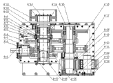
Fig. 3 is the utility model reducer structure section-drawing.
Among the figure: electrical motor 1, coupler 2, hand brake lock 3, retarder 4, electro-hydraulic brake device 5, roll device 6, base 7; Shaft gear 4-1 covers 4-2,4-11,4-18 thoroughly, a set of cups 4-3,4-20, dual gear 4-4, lock ring 4-5 synchronously; Spring coil 4-6, slide block 4-7, sliding hub 4-8, gear hub 4-9, brake bracket 4-10; Brake wheel 4-12, stifle 4-13,4-14,4-21,4-24,4-27, castellated shaft 4-15, dual gear 4-16, big column gear 4-17; Small cylinder gear 4-19, the axle 4-22 that passes a bridge, carrier gear 4-23, bevel gear wheel 4-25, speed governing axle 4-26.
The specific embodiment
Below in conjunction with accompanying drawing the embodiment of the utility model is done further description:
Embodiment such as Fig. 1,2 and shown in Figure 3: this winch mainly is made up of electrical motor 1, coupler 2, hand brake lock 3, retarder 4, electro-hydraulic brake device 5, roll device 6 and base 7.Base 7 is to be formed by channel-section steel and steel plate assembly welding; Electrical motor 1 is through on the two sections short channel-section steels in left side that are bolted to base 7, and electrical motor 1 is connected with retarder 4 through coupler 2, and hand brake lock 3 is installed on the outside and base 7 of coupler 2 simultaneously; Retarder 4 is through being bolted to the middle part of base 7; Electro-hydraulic brake device 5 is installed on the brake wheel 4-12 and base 7 of retarder 4 simultaneously, and the supporting base of roll device 6 is through being bolted on the base 7, and retarder 4 is meshed with the bull gear of roll device 6 through carrier gear 4-23; The drive reel rotates to be realized putting rope and receives the action of restricting, and carrier gear 4-23 and bull gear outside are sealed with protective cover.Roll device 6 mainly is made up of reel, drum shaft, bull gear, supporting base and protective cover.Retarder 4 mainly is made up of last lower box, input shaft 4-1 assembly, speed governing axle 4-26 assembly, castellated shaft 4-15 assembly, pass a bridge axle 4-22 assembly, speed regulation device and brake wheel 4-12.Wherein, speed regulation device mainly is made up of speed regulating handle, governor lever, shifting fork bar, shift fork, shifting block.Bevel gear wheel 4-25, dual gear 4-4, synchronizer assembly, brake bracket 4-10 mainly are housed on the speed governing axle 4-26.Synchronizer assembly mainly is made up of synchronous lock ring 4-5, sliding hub 4-8, slide block 4-7, spring coil 4-6, gear hub 4-9.Brake bracket 4-10 is processed into through hole in the middle part; Bearing supporting speed governing axle 4-26 is housed in the hole; Brake bracket 4-10 one end is processed with gear and dual gear 4-16 engagement is together rotated, and male cone (strobilus masculinus) is processed in the gear outer end, and brake bracket 4-10 is equipped with bearing in the outside; The other end is processed into spline and brake wheel 4-12 assembling, and brake wheel 4-12 is provided with the pressing plate 4-13 that is fixed.Stretch out the outer brake bracket 4-12 of retarder 4 casings and be provided with and cover 4-11, cover 4-11 thoroughly and be provided with seal ring.The transmission of retarder 4 drives speed governing axle 4-26 by shaft gear 4-1 and bevel gear wheel 4-25 engaged transmission through bevel gear wheel 4-25, and by speed governing axle 4-26 driven gear hub 4-9, gear hub 4-9 drives sliding hub 4-8, and sliding hub 4-8 divides the two-way transmission by fork controls.When sliding hub 4-8 and dual gear 4-4 engagement; Big column gear 4-17 engagement on miniature gears on the dual gear 4-4 and the castellated shaft 4-15; Thereby drive the small cylinder gear 4-19 on the castellated shaft 4-15; Small cylinder gear 4-19 passes motion to the bull gear that tightens together with reel through carrier gear 4-23, thereby has realized the quick operation of winch.When the gear mesh on sliding hub 4-8 and the brake bracket 4-10; Gear on the brake bracket 4-10 and dual gear 4-16 engagement; Big gear wheel engagement on miniature gears on the dual gear 4-16 and the dual gear 4-4; Miniature gears on the dual gear 4-4 again with castellated shaft 4-15 on big column gear 4-17 engagement; Thereby drive the small cylinder gear 4-19 on the castellated shaft 4-15, small cylinder gear 4-19 passes motion to the bull gear that tightens together with reel through carrier gear 4-23, thereby has realized the slow running of winch.Each cardan-shaft suspension place is equipped with bearing; Be equipped with axle sleeve between gear and gear; Cover thoroughly 4-2 and the 4-11 except that gear wheel shaft 4-1 and brake bracket 4-10 place are provided with, castellated shaft 4-15 two ends, speed governing axle 4-26 and 4-22 one end of passing a bridge are equipped with stifle 4-14,4-21,4-27,4-24.
Claims (5)
1. a mining double speed is used winch more; Comprise base and be installed in electrical motor, coupler, hand brake lock, retarder, electro-hydraulic brake device and the roll device on the base; Described motor is connected with retarder through coupler; The hand brake lock is connected with coupler, and retarder is connected with roll device, and the electro-hydraulic brake device is connected with the brake wheel of retarder front side; Retarder comprises casing and is arranged on input shaft assembly, speed governing Shaft assembly, castellated shaft assembly and the gap bridge Shaft assembly in the casing that described input shaft assembly comprises input shaft and is fixed on the shaft gear on the input shaft; Described speed governing Shaft assembly comprises the speed governing axle and is installed in bevel gear wheel, first dual gear, speed regulation device and the brake bracket on the speed governing axle that described castellated shaft assembly comprises castellated shaft and is installed in second dual gear, the big column gear on the castellated shaft; Described gap bridge Shaft assembly comprises passes a bridge axle and is installed in the carrier gear on the axle of passing a bridge; Described speed regulation device comprise governor lever and with governor lever bonded assembly shifting block; It is characterized in that: between first dual gear of described speed governing axle and brake bracket, also be provided with synchronizer assembly; This synchronizer assembly comprises: synchronous lock ring, combined cover, slide block and gear hub, and described gear hub is fixed on the speed governing axle, and gear hub is provided with external toothing; In described combined cover outer setting groove is arranged; Described shifting block is arranged in the described groove, in the set inside of combined cover internally toothed annulus is arranged, the internally toothed annulus of described combined cover and the engagement of the external toothing of gear hub; Slide block is provided with a convexity, and this convexity cooperates with sliding hub internally toothed annulus central slot; Described synchronous lock ring is arranged on the both sides of gear hub, and this synchronous lock ring endoporus is the conical surface, and the outside is the little gear ring of an end band chamfering, and this little gear ring can mesh with the internally toothed annulus of described combined cover; Described brake bracket is provided with and the said second dual gear ingear brake bracket gear, and described first dual gear and brake bracket gear are provided with and the suitable conical surface of described synchrolock annular conical surface.
2. mining double speed according to claim 1 is used winch more, it is characterized in that: described synchronizer assembly also comprises a spring coil, and this spring coil is arranged on described slide block inner ring.
3. mining double speed according to claim 1 is used winch more, it is characterized in that: described roll device comprises reel, drum shaft, bull gear, supporting base and protective cover.
4. mining double speed according to claim 1 is used winch more, it is characterized in that: said electro-hydraulic brake device is located at the retarder front side, and the coupler between motor and the retarder is provided with the hand brake lock.
5. use winch according to claim 1,2,3 or 4 described mining double speeds more; It is characterized in that: said brake bracket is a logical structure in; Brake bracket is inner to be connected through bearing with the speed governing axle; Brake bracket one end is processed with male splines and is connected with the brake wheel female splines, and the other end is processed described brake bracket gear.
Priority Applications (1)
| Application Number | Priority Date | Filing Date | Title |
|---|---|---|---|
| CN2011201083361U CN202265353U (en) | 2011-04-14 | 2011-04-14 | Mining double-speed multi-purpose winch |
Applications Claiming Priority (1)
| Application Number | Priority Date | Filing Date | Title |
|---|---|---|---|
| CN2011201083361U CN202265353U (en) | 2011-04-14 | 2011-04-14 | Mining double-speed multi-purpose winch |
Publications (1)
| Publication Number | Publication Date |
|---|---|
| CN202265353U true CN202265353U (en) | 2012-06-06 |
Family
ID=46156161
Family Applications (1)
| Application Number | Title | Priority Date | Filing Date |
|---|---|---|---|
| CN2011201083361U Expired - Lifetime CN202265353U (en) | 2011-04-14 | 2011-04-14 | Mining double-speed multi-purpose winch |
Country Status (1)
| Country | Link |
|---|---|
| CN (1) | CN202265353U (en) |
Cited By (2)
| Publication number | Priority date | Publication date | Assignee | Title |
|---|---|---|---|---|
| CN102180420A (en) * | 2011-04-14 | 2011-09-14 | 淮北万源工贸有限责任公司 | Mining double-speed multi-purpose winch |
| CN109132903A (en) * | 2018-11-08 | 2019-01-04 | 南京禄口起重机械有限公司 | Electric block double-speed motor driving device at a slow speed |
-
2011
- 2011-04-14 CN CN2011201083361U patent/CN202265353U/en not_active Expired - Lifetime
Cited By (2)
| Publication number | Priority date | Publication date | Assignee | Title |
|---|---|---|---|---|
| CN102180420A (en) * | 2011-04-14 | 2011-09-14 | 淮北万源工贸有限责任公司 | Mining double-speed multi-purpose winch |
| CN109132903A (en) * | 2018-11-08 | 2019-01-04 | 南京禄口起重机械有限公司 | Electric block double-speed motor driving device at a slow speed |
Similar Documents
| Publication | Publication Date | Title |
|---|---|---|
| CN102180420B (en) | Mining double-speed multi-purpose winch | |
| US8523727B2 (en) | Multi ratio drive | |
| CN102328886B (en) | Winch reducer | |
| CN205033943U (en) | Explosion -proof multi -function vehicle's wet -type braking transaxle for coal mine | |
| CN201651180U (en) | Shifting-fork gear-shifting two-gear speed reduction box | |
| CN202164067U (en) | Hoisting speed reducer | |
| CN202265353U (en) | Mining double-speed multi-purpose winch | |
| WO2014120065A1 (en) | Gear box for a vehicle and vehicle comprising such gear box | |
| CN201619978U (en) | Double-speed hydraulic winch | |
| CN101234733A (en) | Double-speed shunting winch composed of planet speed change mechanism | |
| CN201619982U (en) | Speed-variable hydraulic winch | |
| CN201329806Y (en) | Rear axle for electric vehicle | |
| CN106122453A (en) | A kind of walking winding speed reducing, moving winding mechanism and rotary drilling rig | |
| CN203902777U (en) | Planetary gear mechanism and speed changer and bicycle with same | |
| CN101423182B (en) | Twin driving chain hoister | |
| CN204185165U (en) | Shaft drive fast reserve strand grinding machine | |
| CN207195580U (en) | A kind of hub reduction axle assembly | |
| CN102120549B (en) | Winch speed reducer for mines | |
| CN202242962U (en) | Clutch structure connected with speed reducer | |
| CN202337662U (en) | Mining winch speed reducer | |
| CN202766177U (en) | Symmetrical mine carrying and transporting winch | |
| CN201309815Y (en) | Power winch device of conical brake | |
| CN201619974U (en) | Hydraulic winch without brake | |
| CN103161899A (en) | Reversible bearing variator | |
| CN203472825U (en) | Wet-type braking driving axle |
Legal Events
| Date | Code | Title | Description |
|---|---|---|---|
| C14 | Grant of patent or utility model | ||
| GR01 | Patent grant | ||
| AV01 | Patent right actively abandoned |
Granted publication date: 20120606 Effective date of abandoning: 20130515 |
|
| RGAV | Abandon patent right to avoid regrant |