CN202240382U - Special numerical control machine tool for automobile recirculating ball steering engines - Google Patents
Special numerical control machine tool for automobile recirculating ball steering engines Download PDFInfo
- Publication number
- CN202240382U CN202240382U CN2011203388862U CN201120338886U CN202240382U CN 202240382 U CN202240382 U CN 202240382U CN 2011203388862 U CN2011203388862 U CN 2011203388862U CN 201120338886 U CN201120338886 U CN 201120338886U CN 202240382 U CN202240382 U CN 202240382U
- Authority
- CN
- China
- Prior art keywords
- plate
- mandrel
- base plate
- bearing
- press
- Prior art date
- Legal status (The legal status is an assumption and is not a legal conclusion. Google has not performed a legal analysis and makes no representation as to the accuracy of the status listed.)
- Expired - Fee Related
Links
Images


Abstract
The utility model belongs to the field of assembly equipment for automobile recirculating ball steering engines, and relates to a special numerical control machine tool for automobile recirculating ball steering engines. The special numerical control machine tool includes a machine tool body, jacking devices, rotating clamps, double-shaft tightening devices, pressing devices, a suspension device, an electric cabinet and the like, wherein a bracket is mounted in the middle of a worktable of the machine tool body, the suspension device is mounted at the top end of the bracket, the rotating clamps are mounted on the worktable of the machine tool body through guide rails, the electric cabinet is arranged at the upper end of the bracket, the double-shaft tightening devices are respectively hung on the two sides of the electric cabinet through the suspension device, a display and a control panel are respectively mounted on the other two side surfaces of the electric cabinet, and the pressing devices are mounted on the bracket below the display and the control panel. Through the rotating clamps, the assembly of all the parts can be finished through one-step clamping, so as to solve the problems of large labor intensity of assemblers and poor quality in the prior art; and through an advanced numerical control programming system, the special numerical control machine tool achieves the adjustment of the tightening parameters of screws on any product, so as to meet the assembly requirements of multiple varieties.
Description
Technical field
The utility model relates to a kind of automobile circulation ball steering box assembling control specific machine, belongs to automobile circulation ball steering box assembly equipment field.
Background technology
Automobile circulation ball steering box is one of automobile important components, and the quality of its assembly quality directly affects the driving safety of automobile.The assembling of automobile circulation ball steering box at present is manually to clamp platform through many to accomplish, and not only the occupation of land of equipment is big, and assembly quality can not be monitored in real time, and working strength of workers is big, efficiency of assembling is low, and the uniformity of product assembling is very poor.
Summary of the invention
The purpose of the utility model is: provide a kind of assembly quality to monitor in real time; And reliable in quality, efficient height; Can not monitor in real time to solve existing automobile circulation ball steering box assembly quality; And working strength of workers is big, efficiency of assembling is low, the automobile circulation ball steering box assembling control specific machine of problem of poor quality.
The utility model is to realize above-mentioned purpose through following technical scheme:
A kind of automobile circulation ball steering box assembling control specific machine; It is made up of lathe bed, raising plate, rolling clamp, support, twin shaft device for screwing up, press-loading apparatus, suspension apparatus, electric cabinet; It is characterized in that: be crosswise in the lathe bed and be provided with jacking apparatus; The work top middle part of lathe bed is equipped with support, and cantilever tip is equipped with suspension apparatus, through jacking apparatus raising plate is installed on the lathe bed work top of support periphery; The lathe bed work top of the inside and outside both sides of raising plate is provided with guide rail, and rolling clamp is movably arranged on the lathe bed work top through guide rail; Described support is the cuboid that is made up of four root posts; The support upper end is provided with electric cabinet; Wherein the both sides of electric cabinet are lifted with the twin shaft device for screwing up respectively through suspension apparatus; The both side surface in addition of electric cabinet is separately installed with display screen and controls screen; Be symmetrically installed with press-loading apparatus respectively through column on display screen and the support of controlling screen below, described twin shaft device for screwing up and press-loading apparatus are corresponding with raising plate respectively, described twin shaft device for screwing up, press-loading apparatus, display screen and control screen and be connected with electric cabinet through lead respectively.
Described suspension apparatus is made up of guide type shoe, guide post, expansion hinge, bearing frame, Spring balancer; The upper surface two ends of guide type shoe are equipped with bearing frame through guide post respectively; Be lifted with Spring balancer on the bearing frame; The guide type shoe lower surface of guide post below is provided with expansion hinge, and Spring balancer is connected with expansion hinge through steel wire cable.
Described rolling clamp is made up of base plate, rotor plate, runing rest, the plate of remodeling, mandrel cover plate, bearing block, scroll wheel, mandrel, guide bearing, locating hole, handle, anti-collision block; Through mandrel and mandrel cover plate rotor plate is installed on the base plate; One end of base plate is equipped with anti-collision block; Angle Thursday, limit of base plate is respectively arranged with guide bearing, and the lower surface of base plate is provided with scroll wheel and locating hole, and the upper surface of rotor plate is equipped with the plate of remodeling by symmetrically arranged bearing block through runing rest; Wherein the runing rest in the bearing block outside is provided with locating part, and the runing rest in another bearing block outside is provided with handle.
Described twin shaft device for screwing up is made up of protective plate, control cabinet, bearing, joystick, electric tightening axle, telescopic head, base plate, turning cylinder, top board, slide plate, pitch-changing mechanism, servomotor; The base plate top is provided with top board through connecting rod; On the connecting rod between base plate and the top board protective plate is housed, wherein the outer surface of a protective plate is equipped with control cabinet, through bearing turning cylinder is installed on the top board; The upper surface of base plate is symmetrically installed with slide plate through slide rail; Be separately installed with the electric tightening axle through pitch-changing mechanism on the slide plate, the rear end of electric tightening axle is provided with servomotor, and floor below is symmetrically arranged with telescopic head; Telescopic head passes base plate and is connected with the electric tightening axle respectively, is respectively arranged with joystick on the protective plate of described telescopic head both sides.
Described press-loading apparatus by rocking arm, manually Pneumatic valve, holder, press-fit cylinder, mount pad, connecting plate, rotating shaft, fixed knob, lock pad, thrust ball bearing, mandrel B, end cap and constitute; Rotating shaft is installed in the holder; The rotating shaft upper end is equipped with mandrel B through fixed knob, and mandrel B goes up and is fixed with rocking arm through thrust ball bearing, and rocking arm one end is equipped with through mount pad and press-fits cylinder and manual Pneumatic valve; The rocking arm of mount pad one side is provided with controls handle; Described mandrel B upper end port is provided with lock pad, and mandrel B lower end port is equipped with end cap through bolt, in the rotating shaft between described holder and the mandrel B connecting plate is installed.
The beneficial effect of the utility model is:
Simple in structure, the advantages of small volume of this automobile circulation ball steering box assembling control specific machine; Pass through its circular workbench in the course of work; And positioner of installing on the work top and jacking clamping device; It is smooth and easy to make that rolling clamp circulates on work top, and locatees and clamp accurately, reliably; Through rolling clamp, can adjust the attitude of steering box (workpiece) arbitrarily, realized clamping No. one time; Can accomplish the assembly work of all parts; Through suspension apparatus lifting workpiece, reduced labor strength, improved operating efficiency; Avoided existing automobile circulation ball steering box assembler's labour intensity big, efficiency of assembling is low, ropy problem.Simultaneously, the utility model adopts advanced NC Programming System, can regulate, monitor, show and store the parameter of tightening of the screw of any product; And can control the spacing of tightening axle automatically, exactly, satisfy many kinds assembling demands.
Description of drawings:
Fig. 1 is the structural representation of the utility model;
Fig. 2 is the structural representation of the lathe bed of the utility model;
Fig. 3 is the suspension apparatus of the utility model and the structural representation of support;
Fig. 4 is the main TV structure sketch map of the rolling clamp of the utility model;
Fig. 5 is the structural representation of looking up of the rolling clamp of the utility model;
Fig. 6 is the main TV structure sketch map of the twin shaft device for screwing up of the utility model;
Fig. 7 is the sectional structure sketch map of the twin shaft device for screwing up of the utility model;
Fig. 8 is the main TV structure sketch map of the press-loading apparatus of the utility model;
Fig. 9 is the side-looking structural representation of the press-loading apparatus of the utility model.
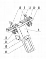
Among the figure: 1, lathe bed, 2, raising plate, 3, rolling clamp, 4, support, 5, the twin shaft device for screwing up, 6, press-loading apparatus, 7, suspension apparatus, 8, electric cabinet; 9, guide type shoe, 10, guide post, 11, expansion hinge, 12, bearing frame, 13, Spring balancer, 14, steel wire cable, 15, guide rail, 16, base plate; 17, rotor plate, 18, locating part A, 19, runing rest, 20, the plate of remodeling, 21, the mandrel cover plate, 22, bearing block, 23, scroll wheel, 24, mandrel; 25, guide bearing, 26, locating hole, 27, handle, 28, anti-collision block, 29, locating part B, 30, protective plate, 31, control cabinet; 32, bearing, 33, joystick, 34, the electric tightening axle, 35, telescopic head, 36, base plate, 37, turning cylinder, 38, top board; 39, slide plate, 40, pitch-changing mechanism, 41, servomotor, 42, connecting rod, 43, slide rail, 44, display screen, 45, control screen; 46, column, 47, rocking arm, 48, manual Pneumatic valve, 49, holder, 50, press-fit cylinder, 51, mount pad, 52, connecting plate; 53, rotating shaft, 54, fixed knob, 55, lock pad, 56, thrust ball bearing, 57, mandrel B, 58, end cap, 59, control handle.
The specific embodiment:
This automobile circulation ball steering box assembling control specific machine is made up of lathe bed 1, raising plate 2, rolling clamp 3, support 4, twin shaft device for screwing up 5, press-loading apparatus 6, suspension apparatus 7, electric cabinet 8.Be crosswise in the lathe bed 1 and be provided with jacking apparatus (not drawing among the figure), lathe bed work top middle part is equipped with support 4, and support 4 tops are installed with suspension apparatus 7.Suspension apparatus 7 is made up of guide type shoe 9, guide post 10, expansion hinge 11, bearing frame 12, Spring balancer 13; The upper surface two ends of guide type shoe 9 are equipped with bearing frame 12 through guide post 10 respectively; Be lifted with Spring balancer 13 on the bearing frame 12; Guide type shoe 9 lower surfaces of guide post 10 belows are provided with expansion hinge 11, and Spring balancer 13 is connected with expansion hinge 11 through steel wire cable 14.Locating part A18,
Through jacking apparatus raising plate 2 is installed on the lathe bed work top of support 4 peripheries, lathe bed 1 work top of raising plate 2 inside and outside both sides is provided with guide rail 15, and rolling clamp 3 is movably arranged on lathe bed 1 work top through guide rail 15.Rolling clamp 3 is made up of base plate 16, rotor plate 17, runing rest 19, the plate 20 of remodeling, mandrel cover plate 21, bearing block 22, scroll wheel 23, mandrel 24, guide bearing 25, locating hole 26, handle 27, anti-collision block 28; Through mandrel 24 and mandrel cover plate 21 rotor plate 17 is installed on the base plate 16; One end of base plate 16 is equipped with anti-collision block 28; Angle Thursday, limit of base plate 16 is respectively arranged with guide bearing 25, and the lower surface of base plate 16 is provided with scroll wheel 23 and locating hole 26, and the upper surface of rotor plate 17 is equipped with the plate 20 of remodeling by symmetrically arranged bearing block 22 through runing rest 19; Wherein the runing rest 19 in a bearing block 22 outsides is provided with locating part B29; Be used for fixing the plate 20 of remodeling and use, the runing rest 19 in another bearing block 22 outsides is provided with handle 27, uses with Rotation With Changing template 20.The marginal position of rotor plate 17 is provided with locating part A18, and locating part A18 inserts with locating hole 26 and is connected.Rotor plate 17 is that the axle center can be 360 degree rotations on base plate 16 with mandrel 24, and rolling clamp 3 can be done circumference along the lathe bed work top through guide rail 15 and rotate.
The both side surface in addition of electric cabinet 8 is separately installed with display screen 44 and controls screen 45, and display screen 44 is symmetrically installed with press-loading apparatus 6 with controlling on the support 4 that shields 45 belows respectively through column 46.Press-loading apparatus 6 by Rocker arm 47, manually Pneumatic valve 48, holder 49, press-fit cylinder 50, mount pad 51, connecting plate 52, rotating shaft 53, fixed knob 54, lock pad 55, thrust ball bearing 56, mandrel B57, end cap 58 and constitute; Rotating shaft 53 is installed in the holder 49; Rotating shaft 53 upper ends are equipped with mandrel B57 through fixed knob 54; Mandrel B57 goes up and is fixed with Rocker arm 47 through thrust ball bearing 56; Rocker arm 47 one ends are equipped with through mount pad 51 and press-fit cylinder 50 and manual Pneumatic valve 48, and the Rocker arm 47 of mount pad 51 1 sides is provided with controls handle 59.Mandrel B57 upper end port is provided with lock pad 55, and mandrel B57 lower end port is equipped with end cap 58 through bolt, in the rotating shaft 53 between holder 49 and the mandrel B57 connecting plate 52 is installed.Press-loading apparatus 6 is fixedly mounted on the column 46 of support 4 through connecting connecting plate 52.
Twin shaft device for screwing up 5 is corresponding with raising plate 2 respectively with press-loading apparatus 6, twin shaft device for screwing up 5, press-loading apparatus 6, display screen 44 and control screen 45 and be connected with electric cabinet 8 through lead respectively.
During work; At first with workpiece to be assembled (steering box housing) clamping to the plate 20 of remodeling of rolling clamp 3; Raising plate 2 startups clamp rolling clamp 3 jackings; Respectively that rotor plate 17 is fixing with the plate 20 of remodeling through locating part A18 and locating part B29, through press-loading apparatus 6 accessory (nut and valve assembly) is pressed into then and is assembled in the workpiece (steering box housing).Start raising plate 2 playback, rolling clamp 3 is rotated along the lathe bed work top through guide rail 15, enter into twin shaft device for screwing up 5 stations, accessory (valve body bolt and spring washer circle) is screwed in the workpiece (steering box housing) through twin shaft device for screwing up 5.
After accessory (valve body bolt and spring washer circle) is screwed into workpiece (steering box housing); Rolling clamp 3 rotates along the lathe bed work top through guide rail 15; Enter into side cover and arm axle assembly assembly station (being another press-loading apparatus 6); At first adopt protective sleeve that the spline of accessory arm axle assembly to be assembled is entangled, in the cross-drilled hole with its workpiece of packing into (steering box housing), take out protective sleeve then; Through handle 27 plate 20 of remodeling of rolling clamp 3 is turned to level, with press-loading apparatus 6 the accessory side cover is press-fited in the workpiece (steering box housing) again.
This automobile circulation ball steering box assembling control specific machine adopts advanced NC Programming System, through display screen 44, control screen 45 and electric cabinet 8 and can regulate, monitor, show and store the parameter of tightening of the screw of any product; And can control the spacing of tightening axle automatically, exactly, satisfy many kinds assembling demands; Adopt the circular table face, it is smooth and easy to guarantee that rolling clamp 3 circulates on work top, and location and clamping are accurately, reliably; Realize the assembly work that No. a time clamping can be accomplished all parts, reduced labour intensity, realized the moving of upper and lower, front, rear, left and right of twin shaft device for screwing up 5 through suspension apparatus 7, safe and convenient to use; Reduce floor space simultaneously, improved assembly quality.
Claims (5)
1. an automobile circulation ball steering box assembles control specific machine; It is made up of lathe bed (1), raising plate (2), rolling clamp (3), support (4), twin shaft device for screwing up (5), press-loading apparatus (6), suspension apparatus (7), electric cabinet (8); It is characterized in that: be crosswise in the lathe bed (1) and be provided with jacking apparatus; The work top middle part of lathe bed (1) is equipped with support (4); Suspension apparatus (7) is equipped with on support (4) top; Through jacking apparatus raising plate (2) is installed on the lathe bed work top of support (4) periphery, the lathe bed work top of the inside and outside both sides of raising plate (2) is provided with guide rail (15), and rolling clamp (3) is movably arranged on the lathe bed work top through guide rail (15); Described support (4) is a cuboid by four root posts (46) formation; Support (4) upper end is provided with electric cabinet (8); Wherein the both sides of electric cabinet (8) are lifted with twin shaft device for screwing up (5) respectively through suspension apparatus (7); The both side surface in addition of electric cabinet (8) is separately installed with display screen (44) and controls screen (45); Display screen (44) and the support (4) of controlling screen (45) below are gone up and are symmetrically installed with press-loading apparatus (6) respectively through column (46); Described twin shaft device for screwing up (5) and press-loading apparatus (6) are corresponding with raising plate (2) respectively, described twin shaft device for screwing up (5), press-loading apparatus (6), display screen (44) and control screen (45) and be connected with electric cabinet (8) through lead respectively.
2. automobile circulation ball steering box assembling control specific machine according to claim 1; It is characterized in that: described suspension apparatus (7) is made up of guide type shoe (9), guide post (10), expansion hinge (11), bearing frame (12), Spring balancer (13); The upper surface two ends of guide type shoe (9) are equipped with bearing frame (12) through guide post (10) respectively; Be lifted with Spring balancer (13) on the bearing frame (12); Guide type shoe (9) lower surface of guide post (10) below is provided with expansion hinge (11), and Spring balancer (13) is connected with expansion hinge (11) through steel wire cable (14).
3. automobile circulation ball steering box assembling control specific machine according to claim 1; It is characterized in that: described rolling clamp (3) is made up of base plate (16), rotor plate (17), runing rest (19), the plate of remodeling (20), mandrel cover plate (21), bearing block (22), scroll wheel (23), mandrel (24), guide bearing (25), locating hole (26), handle (27), anti-collision block (28); Base plate (16) is gone up and through mandrel (24) and mandrel cover plate (21) rotor plate (17) is installed; One end of base plate (16) is equipped with anti-collision block (28); Angle Thursday, limit of base plate (16) is respectively arranged with guide bearing (25); The lower surface of base plate (16) is provided with scroll wheel (23) and locating hole (26); The upper surface of rotor plate (17) is equipped with the plate of remodeling (20) by symmetrically arranged bearing block (22) through runing rest (19); Wherein the runing rest (19) in a bearing block (22) outside is provided with locating part B (29), and the runing rest (19) in another bearing block (22) outside is provided with handle (27).
4. automobile circulation ball steering box assembling control specific machine according to claim 1; It is characterized in that: described twin shaft device for screwing up (5) is made up of protective plate (30), control cabinet (31), bearing (32), joystick (33), electric tightening axle (34), telescopic head (35), base plate (36), turning cylinder (37), top board (38), slide plate (39), pitch-changing mechanism (40), servomotor (41); Base plate (36) top is provided with top board (38) through connecting rod (42); On the connecting rod (42) between base plate (36) and the top board (38) protective plate (30) is housed; Wherein the outer surface of a protective plate (30) is equipped with control cabinet (31); Top board (38) is gone up and through bearing (32) turning cylinder (37) is installed; The upper surface of base plate (36) is symmetrically installed with slide plate (39) through slide rail (43); Slide plate (39) is gone up and is separately installed with electric tightening axle (34) through pitch-changing mechanism (40), and the rear end of electric tightening axle (34) is provided with servomotor (41), and base plate (36) below is symmetrically arranged with telescopic head (35); Telescopic head (35) passes base plate (36) and is connected with electric tightening axle (34) respectively, is respectively arranged with joystick (33) on the protective plate (30) of described telescopic head (35) both sides.
5. automobile circulation ball steering box assembling control specific machine according to claim 1; It is characterized in that: described press-loading apparatus (6) by rocking arm (47), manually Pneumatic valve (48), holder (49), press-fit cylinder (50), mount pad (51), connecting plate (52), rotating shaft (53), fixed knob (54), lock pad (55), thrust ball bearing (56), mandrel B (57), end cap (58) and constitute; Rotating shaft (53) is installed in the holder (49); Rotating shaft (53) upper end is equipped with mandrel B (57) through fixed knob (54); Mandrel B (57) goes up and is fixed with rocking arm (47) through thrust ball bearing (56); rocking arm (47) one ends are equipped with through mount pad (51) and press-fit cylinder (50) and manual Pneumatic valve (48); the rocking arm (47) of mount pad (51) one sides is provided with controls handle (59); described mandrel B (57) upper end port is provided with lock pad (55), and mandrel B (57) lower end port is equipped with end cap (58) through bolt, in the rotating shaft (53) between described holder (49) and the mandrel B (57) connecting plate (52) is installed.
Priority Applications (1)
| Application Number | Priority Date | Filing Date | Title |
|---|---|---|---|
| CN2011203388862U CN202240382U (en) | 2011-09-10 | 2011-09-10 | Special numerical control machine tool for automobile recirculating ball steering engines |
Applications Claiming Priority (1)
| Application Number | Priority Date | Filing Date | Title |
|---|---|---|---|
| CN2011203388862U CN202240382U (en) | 2011-09-10 | 2011-09-10 | Special numerical control machine tool for automobile recirculating ball steering engines |
Publications (1)
| Publication Number | Publication Date |
|---|---|
| CN202240382U true CN202240382U (en) | 2012-05-30 |
Family
ID=46101683
Family Applications (1)
| Application Number | Title | Priority Date | Filing Date |
|---|---|---|---|
| CN2011203388862U Expired - Fee Related CN202240382U (en) | 2011-09-10 | 2011-09-10 | Special numerical control machine tool for automobile recirculating ball steering engines |
Country Status (1)
| Country | Link |
|---|---|
| CN (1) | CN202240382U (en) |
Cited By (3)
| Publication number | Priority date | Publication date | Assignee | Title |
|---|---|---|---|---|
| CN105397464A (en) * | 2015-11-30 | 2016-03-16 | 北京天宜上佳新材料有限公司 | Rapid assembling device for brake pads |
| CN105834930A (en) * | 2016-04-22 | 2016-08-10 | 黄斌 | Electric-rotation moving type clamping device |
| CN106670891A (en) * | 2017-01-20 | 2017-05-17 | 武汉恒精电热设备有限公司 | Movable swing arm type machine tool cooling spraying mechanism |
-
2011
- 2011-09-10 CN CN2011203388862U patent/CN202240382U/en not_active Expired - Fee Related
Cited By (4)
| Publication number | Priority date | Publication date | Assignee | Title |
|---|---|---|---|---|
| CN105397464A (en) * | 2015-11-30 | 2016-03-16 | 北京天宜上佳新材料有限公司 | Rapid assembling device for brake pads |
| CN105834930A (en) * | 2016-04-22 | 2016-08-10 | 黄斌 | Electric-rotation moving type clamping device |
| CN106670891A (en) * | 2017-01-20 | 2017-05-17 | 武汉恒精电热设备有限公司 | Movable swing arm type machine tool cooling spraying mechanism |
| CN106670891B (en) * | 2017-01-20 | 2019-02-05 | 武汉恒精电热设备有限公司 | Active pendulum arm-type lathe chilling spray mechanism |
Similar Documents
| Publication | Publication Date | Title |
|---|---|---|
| CN201900925U (en) | Multi-head stereoscopic numerical control engraver | |
| CN209793657U (en) | Aircraft engine assembly process rack | |
| CN202240382U (en) | Special numerical control machine tool for automobile recirculating ball steering engines | |
| CN205414825U (en) | Welding positioner | |
| CN202963872U (en) | Automatic positioning and welding tool device for axle chassis | |
| CN103659130B (en) | The automatic positioning welding tooling device of axle base plate | |
| CN206344070U (en) | A kind of horizontal automatic screw nailing device | |
| CN203635988U (en) | Angle-adjustable drilling machine | |
| CN219959209U (en) | Cover cap edge covering device | |
| CN210334441U (en) | Drilling machine for machining parts of wind driven generator | |
| CN111922949A (en) | Automobile part machining jig for multidirectional rotation and using method thereof | |
| CN217965840U (en) | Multi-degree-of-freedom side milling type planer type milling machine for titanium plate blank machining | |
| CN206605185U (en) | A kind of movement in a curve servo slide table | |
| CN108406453B (en) | Numerical control knife sharpener | |
| CN215280663U (en) | Adjustable support for automobile welding fixture | |
| CN212918374U (en) | Automatic screw twisting machine | |
| TW201433407A (en) | CNC horizontal type dual spindles double efficiency machine center | |
| CN109333339B (en) | Wheel hub numerical control polishing machine and working method thereof | |
| CN206105117U (en) | Four -axis welding robot | |
| CN215035163U (en) | Full-automatic servo bolt assembly electric control system | |
| CN220006333U (en) | Novel plasma cutting robot workstation | |
| CN216298917U (en) | Double-grinding-head grinding machine for graphite mold | |
| CN217690326U (en) | Multi-shaft machining training equipment for worker technology | |
| CN216030423U (en) | Be used for accurate part fast switch over clamping tool | |
| CN220480986U (en) | Handle processing positioning jig in car door |
Legal Events
| Date | Code | Title | Description |
|---|---|---|---|
| C14 | Grant of patent or utility model | ||
| GR01 | Patent grant | ||
| CF01 | Termination of patent right due to non-payment of annual fee |
Granted publication date: 20120530 Termination date: 20170910 |
|
| CF01 | Termination of patent right due to non-payment of annual fee |