CN202224886U - Positioning device for welding screw stud - Google Patents
Positioning device for welding screw stud Download PDFInfo
- Publication number
- CN202224886U CN202224886U CN2011203010628U CN201120301062U CN202224886U CN 202224886 U CN202224886 U CN 202224886U CN 2011203010628 U CN2011203010628 U CN 2011203010628U CN 201120301062 U CN201120301062 U CN 201120301062U CN 202224886 U CN202224886 U CN 202224886U
- Authority
- CN
- China
- Prior art keywords
- positioning
- hole
- welding
- template
- locating
- Prior art date
- Legal status (The legal status is an assumption and is not a legal conclusion. Google has not performed a legal analysis and makes no representation as to the accuracy of the status listed.)
- Expired - Fee Related
Links
Images


Landscapes
- Resistance Welding (AREA)
Abstract
The utility model aims at providing a positioning device for welding a screw stud for fundamentally solving the problems of great space deviation and low work efficiency in the welding of a traditional screw stud. The positioning device comprises a verticality support leg rod for supporting a welding gun and two positioning support leg rods with internal threads at the bottom. The positioning device is technically characterized in that the bottom of each positioning support leg rod is connected with one end of a positioning pin; the other end of the positioning pin is inserted into a positioning hole of a positioning template; positioning holes and magnetic ring holes which are correspondingly arrayed are formed on the positioning template; a perpendicular bisector of a central connecting line of every two positioning hole and a central line of one magnetic ring hole are positioned on the same straight line; two positioning holes and one magnetic ring hole form a welding group; and a screw stud to be welded is fixedly arranged in the magnetic ring hole of the positioning template. When the positioning device is used for welding, the positioning pin is inserted into the positioning hole of the positioning template so as to ensure that the space of the welded screw stud meets the requirement of positional tolerance. Therefore, the positioning device has the advantages of simple structure, convenience for operation, quickness and accuracy for positioning and remarkably-improved welding quality of the screw stud and work efficiency.
Description
Technical field
The utility model relates to a kind of aid that is used for stud welding equipment, and particularly a kind of spacing that can guarantee to weld a plurality of double-screw bolts in back meets the stud welding that position of related features requires and uses positioner, belongs to the welding field of machining.
Background technology
In the last few years, along with the continuous development of solder technology, stud welding equipment obtained wide model in every field and used.A plurality of generally speaking stud welding operations are because of mainly being leans on pure manual line to look for the point location double-screw bolt to operate, so production efficiency is very low.When the spacing after the stud welding was had the certain position tolerance, the weld job mode space deviations of this stud welding equipment was big, had satisfied not the position of related features requirement of double-screw bolt spacing, and welding quality is difficult to guarantee.
The utility model content
The purpose of the utility model provides a kind of stud welding and uses positioner; Fundamentally solve big, the ineffective problem of space deviations that existing stud welding exists, it is simple in structure, and is easy to operate; The location is quick, accurate, significantly improves stud welding quality and operating efficiency.
The technical scheme of the utility model is: this stud welding comprises that with positioner a perpendicularity that supports welding gun props up the tapped location of foot lever and two bottoms and prop up foot lever; Its technical essential is: the bottom that foot lever is propped up in each said location utilizes an end of the alignment pin that is threaded; The other end of alignment pin inserts in the locating hole of locating template; Locating template is provided with corresponding locating hole and magnet ring hole of arranging; The center line in the perpendicular bisector of per two locating hole lines of centres and a magnet ring hole is on same straight line, and two locating holes and a magnet ring hole constitute a soldering group, and double-screw bolt to be welded is fixed in the magnet ring hole of each soldering group of locating template.
Advantage of the utility model and positive technique effect are: because the locating template of the utility model constitutes a soldering group with two locating holes and a magnet ring hole; Two alignment pins prop up on the foot lever through the location that is threaded in welding gun; Double-screw bolt to be welded is fixed in the magnet ring hole of each soldering group of locating template; So in when welding, as long as two alignment pins are inserted respectively in two locating holes of template, can guarantee stud welding after spacing meet the position of related features requirement.Therefore, this positioning device structure is simple, and is easy to operate, only needs alignment pin is inserted in the locating hole of locating template the perpendicularity of another leg location welding gun of welding gun during operation.Because of locating template is directly controlled the spacing between the double-screw bolt of welding back through the precision of locating hole on it; So the location is quick, accurate; Significantly improve stud welding quality and operating efficiency, and then fundamentally solve big, the ineffective problem of space deviations that existing stud welding exists.
Description of drawings
In conjunction with accompanying drawing the utility model is described further:
Fig. 1 is a kind of structural representation of the utility model;
Fig. 2 is a kind of structural representation of locating template among Fig. 1;
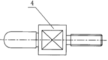
Fig. 3 is a kind of structural representation of alignment pin among Fig. 1;
Fig. 4 is the side view of Fig. 3.
Sequence number explanation among the figure: 1 welding gun, 2 a location foot lever, 3 magnet ring seats, 4 alignment pins, 5 locating templates, 6 perpendicularity are propped up foot lever, 7 locating holes, 8 magnet ring holes, 9 off-load holes.
The specific embodiment
Describe in detail according to Fig. 1 ~ 4 pair the utility model.This stud welding comprises that with positioner a perpendicularity that supports welding gun 1 props up the tapped location of foot lever 6 and two bottoms and prop up parts such as foot lever 2, alignment pin 4 and locating template 5.Wherein the bottom of each location foot lever 2 utilizes the alignment pin 4 threaded ends that are threaded, and the other end of alignment pin 4 inserts in the locating hole 7 of locating template 5.Locating template 5 is provided with corresponding locating hole of arranging 7 and magnet ring hole 8, and the center line in the perpendicular bisector of the line of centres of per two locating holes 7 and a magnet ring hole 8 is on same straight line.Two locating holes 7 and a magnet ring hole 8 constitute a soldering group.The quantity of soldering group should be confirmed according to the quantity of double-screw bolt to be welded.In order to alleviate the weight of locating template 5, be provided with some off-load holes 9 above that, the specification in off-load hole 9 and quantity should be provided with according to actual needs.During stud welding to be welded, it is fixed on through the magnet ring (not shown) in the magnet ring hole 8 of each soldering group of locating template 5.
This positioner inserts in two locating holes 5 of locating template 4 as long as will be connected two alignment pins 3 of foot lever 2 bottom, two location when weld job.
The operation of the processing of the utility model, making and operation is all very simple and convenient; Through the positional precision of the locating hole on the locating template 57 with magnet ring hole 8; The location is quick, accurate; After guaranteeing stud welding, satisfy the requirement of position of related features fully, thereby significantly improve stud welding quality and operating efficiency.
Claims (1)
1. positioner is used in a stud welding; Comprise that a perpendicularity that supports welding gun props up the tapped location of foot lever and two bottoms and prop up foot lever; It is characterized in that: the bottom that foot lever is propped up in each said location utilizes an end of the alignment pin that is threaded; The other end of alignment pin inserts in the locating hole of locating template, and locating template is provided with corresponding locating hole and magnet ring hole of arranging, and the center line in the perpendicular bisector of per two locating hole lines of centres and a magnet ring hole is on same straight line; Two locating holes and a magnet ring hole constitute a soldering group, and double-screw bolt to be welded is fixed in the magnet ring hole of each soldering group of locating template.
Priority Applications (1)
| Application Number | Priority Date | Filing Date | Title |
|---|---|---|---|
| CN2011203010628U CN202224886U (en) | 2011-08-18 | 2011-08-18 | Positioning device for welding screw stud |
Applications Claiming Priority (1)
| Application Number | Priority Date | Filing Date | Title |
|---|---|---|---|
| CN2011203010628U CN202224886U (en) | 2011-08-18 | 2011-08-18 | Positioning device for welding screw stud |
Publications (1)
| Publication Number | Publication Date |
|---|---|
| CN202224886U true CN202224886U (en) | 2012-05-23 |
Family
ID=46075493
Family Applications (1)
| Application Number | Title | Priority Date | Filing Date |
|---|---|---|---|
| CN2011203010628U Expired - Fee Related CN202224886U (en) | 2011-08-18 | 2011-08-18 | Positioning device for welding screw stud |
Country Status (1)
| Country | Link |
|---|---|
| CN (1) | CN202224886U (en) |
Cited By (7)
| Publication number | Priority date | Publication date | Assignee | Title |
|---|---|---|---|---|
| CN104889546A (en) * | 2015-06-05 | 2015-09-09 | 苏州梦之捷焊接技术有限公司 | Stud positioning device of stud welding and application of stud positioning device in short-cycle stud welding |
| CN105598565A (en) * | 2016-03-30 | 2016-05-25 | 胡长建 | Automatic stud welding device applicable to T-shape welding studs |
| CN105598564A (en) * | 2016-03-30 | 2016-05-25 | 胡长建 | Device for realizing full-automatic stud welding of T-type welding stud |
| CN107671393A (en) * | 2017-11-13 | 2018-02-09 | 中国冶集团有限公司 | Connector welder and welding method |
| CN111278594A (en) * | 2017-12-18 | 2020-06-12 | 喜利得股份公司 | Bolt welding gun |
| CN113695717A (en) * | 2021-09-30 | 2021-11-26 | 北京电子科技职业学院 | Manufacturing and optimizing of vehicle body stud welding template |
| CN114932298A (en) * | 2022-06-29 | 2022-08-23 | 中国航发动力股份有限公司 | Positioning fixture for stud welding of curved surface workpiece and use method thereof |
-
2011
- 2011-08-18 CN CN2011203010628U patent/CN202224886U/en not_active Expired - Fee Related
Cited By (9)
| Publication number | Priority date | Publication date | Assignee | Title |
|---|---|---|---|---|
| CN104889546A (en) * | 2015-06-05 | 2015-09-09 | 苏州梦之捷焊接技术有限公司 | Stud positioning device of stud welding and application of stud positioning device in short-cycle stud welding |
| CN105598565A (en) * | 2016-03-30 | 2016-05-25 | 胡长建 | Automatic stud welding device applicable to T-shape welding studs |
| CN105598564A (en) * | 2016-03-30 | 2016-05-25 | 胡长建 | Device for realizing full-automatic stud welding of T-type welding stud |
| CN107671393A (en) * | 2017-11-13 | 2018-02-09 | 中国冶集团有限公司 | Connector welder and welding method |
| CN111278594A (en) * | 2017-12-18 | 2020-06-12 | 喜利得股份公司 | Bolt welding gun |
| CN111278594B (en) * | 2017-12-18 | 2023-03-10 | 喜利得股份公司 | Bolt welding gun |
| CN113695717A (en) * | 2021-09-30 | 2021-11-26 | 北京电子科技职业学院 | Manufacturing and optimizing of vehicle body stud welding template |
| CN114932298A (en) * | 2022-06-29 | 2022-08-23 | 中国航发动力股份有限公司 | Positioning fixture for stud welding of curved surface workpiece and use method thereof |
| CN114932298B (en) * | 2022-06-29 | 2023-08-25 | 中国航发动力股份有限公司 | Positioning clamp for stud welding of curved-surface workpiece and application method of positioning clamp |
Similar Documents
| Publication | Publication Date | Title |
|---|---|---|
| CN202224886U (en) | Positioning device for welding screw stud | |
| CN205967913U (en) | Pipe flange welding position frock | |
| CN202846183U (en) | Machining tool for connecting rod protruding platform surface and bolt hole | |
| CN103100901B (en) | Thin-wall cambered-surface positioning tool for inclined hole punching | |
| CN205020874U (en) | But graduation bores mechanism in radial hole | |
| CN203622010U (en) | Quick clamping and positioning device for machining transmission connecting lever | |
| CN201997784U (en) | Processing clamp for steam turbine guide blade with eccentric cambered surfaces as end surfaces of blade shroud and blade base | |
| CN110666535A (en) | Clamping tool and method for batch processing of polyhedral products | |
| CN204471013U (en) | Novel side bearing base frock | |
| CN102785103B (en) | A kind of fixture for cable clip Milling Process | |
| CN203390580U (en) | Automatic middle-partitioning fixture for milling two side surfaces of coupler yoke | |
| CN204584791U (en) | Shaped piece drilling tool | |
| CN203804615U (en) | Device capable of improving accuracy in perpendicularity of cross-hole drilling | |
| CN205237240U (en) | Special fixture of processing large gear part | |
| CN201769066U (en) | Jaw holder for preparatory positioning | |
| CN201862813U (en) | Drilling fixture for tooth fork | |
| CN203556912U (en) | Combined drilling mold used for drilling and processing work piece | |
| CN206140135U (en) | Cleat positioner | |
| CN204686117U (en) | A kind of accurately spitting drill bushing installing plate | |
| CN104924117A (en) | Modularization tool used for machining L-shaped diesel engine body and use method thereof | |
| CN204800323U (en) | A modularization frock for processing L type diesel engine organism | |
| CN202964169U (en) | Positioning tooling for drilling inclined holes in thin-wall arc surface | |
| CN204621436U (en) | Adopt fixture by the fixed structure of longitudinal wall plate peculiar to vessel and band steel positioning welding | |
| CN203437977U (en) | Locating tool for shifting fork hole boring | |
| CN203031590U (en) | Bench work scribing device for heavy castings |
Legal Events
| Date | Code | Title | Description |
|---|---|---|---|
| C14 | Grant of patent or utility model | ||
| GR01 | Patent grant | ||
| CF01 | Termination of patent right due to non-payment of annual fee |
Granted publication date: 20120523 Termination date: 20160818 |
|
| CF01 | Termination of patent right due to non-payment of annual fee |