The utility model content
In view of this, the utility model provides a kind of LED lamp, the radiating efficiency of the raising radiator of this LED lamp.
For realizing above-mentioned purpose, the utility model provides following technical scheme: a kind of LED lamp comprises: the lamp holder, insulator foot and the radiator that link to each other successively; The LED light-emitting component that is arranged on the said radiator and links to each other with said lamp holder through driver; And be set in the diffuser on said LED light-emitting component and the said radiator, and said radiator is provided with through channel, and said radiator inside is provided with the cavity of placing said driver.
Preferably, the sidewall of said radiator is provided with through channel radially.
Preferably, the top of said radiator is provided with the through channel in the cavity that extends through said radiator.
Preferably, when said radiator sidewall is provided with a plurality of radially through channel, be interconnected between each through channel radially.
Preferably, said through channel and said radially extends through between the through channel in the cavity of said radiator and is interconnected.
Preferably, said LED light-emitting component is provided with on the light-emitting substrate, and said light-emitting substrate is arranged on the sidewall of said radiator and/or the top of said radiator.
Preferably, said radiator comprises first thermal component and second thermal component, and the inside of said first thermal component is provided with the cavity that said driver is set;
One end of said first thermal component links to each other with said insulator foot, and the other end links to each other with said second thermal component;
The sidewall of said second thermal component and/or top are provided with said through channel.
Preferably, the sidewall of said second thermal component and/or top are provided with the light-emitting substrate that the LED light-emitting component is installed.
Preferably, also comprise reflection shield, said reflection shield is set on said second thermal component.
Preferably, the sidewall of said radiator is provided with radiating fin.
Preferably, the top of said diffuser is provided with ventilating duct, and is connected with through channel in the said cavity of extending through of radiator top;
And/or the sidewall of said diffuser is provided with air vent.
Can find out that from above-mentioned technical scheme the utility model embodiment provides a kind of LED lamp, the heat that produces in the LED lamp course of work can be transmitted in the air through radiator heat; Because radiator is provided with through channel; When increasing cooling surface area, reduced the weight and the cost of radiator, realized the convection current of air in radiator inside; Quicken the inner air of radiator and flowed, improved the radiating efficiency of radiator.
Simultaneously, be provided with the cavity of placing driver in radiator inside, the heat that driver produces in the LED lamp course of work so also can distribute preferably, thereby has improved the radiating effect of LED light fixture.
The specific embodiment
To combine the accompanying drawing among the utility model embodiment below, the technical scheme among the utility model embodiment is carried out clear, intactly description, obviously, described embodiment only is the utility model part embodiment, rather than whole embodiment.Based on the embodiment in the utility model, those of ordinary skills are not making the every other embodiment that is obtained under the creative work prerequisite, all belong to the scope of the utility model protection.
In order on the basis that does not increase cost, to improve the radiating efficiency of the radiator of LED lamp, the utility model embodiment discloses a kind of LED lamp, comprising:
The lamp holder, insulator foot and the radiator that link to each other successively; The driver that links to each other with lamp holder, the LED light-emitting component that is arranged on the radiator and links to each other with lamp holder through driver, particularly, lamp holder can directly connect civil power, and the input of driver connects lamp holder, output end of driver connection LED light-emitting component; And be set in the diffuser on LED light-emitting component and the radiator; This radiator is provided with through channel, and this radiator set inside has the cavity of placing driver.
The through channel of this radiator can play the effect of ventilation and heat; Quickening spreader surface flows with inner air; And driver is arranged in the inner cavity of radiator; After the heat that in the LED lamp course of work, is produced by LED light-emitting component and driver was transmitted on the radiator, can be very fast flow with air distributed, and improved the radiating efficiency of radiator.Simultaneously, need not save production cost through increasing the surface area that the radiator volume increases radiator.
Wherein, the mode that through channel is set on the radiator can have multiple, flows as long as can quicken the air of spreader surface, and the radiating efficiency that improves radiator gets final product, and sidewall that can radiator is provided with through channel radially.That is to say that when the LED lamp was vertically placed, the through channel on the radiator can be regarded as the horizontal through channel that on the sidewall of radiator, is provided with.
Certainly, also can be provided with the through channel in the cavity that extends through radiator on the top of radiator.
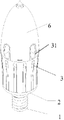
In order clearly to describe the LED lamp of the utility model, referring to Fig. 1, be the structural representation of the embodiment one of a kind of LED lamp of the utility model, this LED lamp comprises:
The lamp holder 1, insulator foot 2 and the radiator 3 that link to each other successively wherein can be through getting ready or engage thread links to each other between lamp holder and the insulator foot, and radiator can link to each other through buckle or engage thread with insulator foot, and other connected mode can certainly be arranged; The driver that links to each other with lamp holder; The LED light-emitting component that is arranged on the radiator 3 and links to each other with lamp holder 1 through driver, particularly, lamp holder can directly connect civil power, and the input of driver connects lamp holder, output end of driver connection LED light-emitting component; This radiator 3 is provided with through channel; Air draught can circulate in this through channel; The cavity (driver does not draw) of placing driver is arranged in the radiator set inside; Like this, the heat that is produced by driver in the LED lamp course of work also can be directly conducted on the radiator, thereby has further reduced the temperature of LED light fixture.
What through channel was concrete can be the through channel radially 31 that on the sidewall of radiator, is provided with.To know and can the heat dissipation channel radially that be provided with on the radiator sidewall be called first through channel 31 in order to describe; When the LED lamp is vertically placed; First through channel 31 can be thought horizontal heat dissipation channel, and the quantity of first through channel can be set (quantity of heat dissipation channel is two in Fig. 1) as required.When a plurality of radially heat dissipation channel is arranged on the radiator sidewall, be interconnected between each heat dissipation channel radially.That is to say that each first through channel communicates in radiator inside.Air draught can flow into from an end of first through channel, and the other end outflow from first through channel forms the passage that ventilates, and air draught also can circulation each other between each first heat dissipation channel.
The outer wall of radiator is provided with the LED light-emitting component; Like the LED light emitting diode; The heat that in the LED lamp work course of work, produces can be transmitted on the radiator; And air draught can flow through first through channel of radiator, thereby the air that has quickened spreader surface flows, and radiator distributes the speeding up of conduction heat in air, radiating efficiency improves.
Wherein, LED light-emitting component on this LED lamp can be arranged on the optional position on the radiator outer wall, in order to improve the LED luminosity, and simplifies installation process; Can the LED light-emitting component be arranged on the light-emitting substrate 4; After radiator assembles, can this light-emitting substrate that LED light-emitting component is installed be assembled on the outer wall of radiator, just this light-emitting substrate is installed on the outer surface of radiator.
Concrete, can this light-emitting substrate 4 that LED light-emitting component is installed be arranged on the sidewall of radiator, what center on radiator can be provided with several such light-emitting substrates 4 in one week of sidewall, and all angles all have light source like this, and lighting angle increases brightness and strengthens.In order further to increase the luminous light source face, can this light-emitting substrate be arranged to the inclined-plane simultaneously, promptly the sidewall of light-emitting substrate and radiator has certain angle.As, can light-emitting substrate be set (that is, not offering the place of through channel on the radiator sidewall) between each first through channel on each sidewall, and each light-emitting substrate 4 to deviate from the radiator sidewall outward-dipping, angled with this sidewall.The quantity of light-emitting substrate can be set as required.
Consider that the LED lamp when mounted may the vertical direction setting; Also horizontally set in the horizontal direction; In order to make LED lamp under the various mounting means all can satisfy the luminosity of all directions; Can light-emitting substrate 4 be installed on the top of radiator, as being provided with the light-emitting substrate 4 that the LED light-emitting component is installed on the top of radiator among Fig. 1, the light-emitting substrate 4 and the radiator top on this radiator top laterally arrange.Can certainly on the radiator sidewall, this light-emitting substrate all be installed with the top.
Referring to Fig. 2 is the structural representation of the embodiment two of a kind of LED lamp of the utility model, and the LED lamp of this embodiment and the difference of embodiment one are that the top at radiator of this LED lamp is provided with the through channel in the cavity that extends through radiator.This through channel extends in the radiator internal cavities along the radiator top always, and air can flow in the radiator internal cavities, and the inner heat of radiator can be dispersed in the middle of the air through the heat dissipation channel on top.
This through channel that is arranged on the radiator top can be called second through channel, and this second through channel 32 extends in the cavity in the radiator along the passway on radiator top always in Fig. 2.In the LED lamp course of work; Driver in the radiator internal cavities also can produce great amount of heat; And the heat that driver produces can the heat conduction be given radiator; Also can directly be dispersed in the air, thereby the heat that has dissipated and produced in the drive operation has solved the heat dissipation problem of driver by second through channel.
Further, can when the radiator top is provided with second heat dissipation channel 32, through channel radially be set also on the sidewall of radiator; I.e. first through channel 31; Through channel radially and extending through from the radiator top between the through channel in the cavity of radiator is interconnected, and that is to say that first through channel and second through channel can communicate in radiator inside; Promptly first heat dissipation channel and second heat dissipation channel intersect to connect, and make the radiator heat-dissipation better effects if.
Because the set inside of radiator has the cavity of placing driver; In order to make the attractive in appearance and safety of producing of LED lamp; Can be arranged on the end of radiator along radiator sidewall through channel radially, through channel radially just is set along the side in the upper end of the cavity that is provided with radiator away from lamp holder.
For the inner cavity of radiator better is set; And the through channel on the radiator rationally is set, and referring to Fig. 3, the structural representation of a kind of LED lamp of the utility model embodiment three; Be with the difference of embodiment one: this radiator 3 can be made up of first thermal component 33 and second thermal component 34; One end of first thermal component 33 links to each other with insulator foot 2, and connected mode can adopt buckle or engage thread to link to each other, and the other end of first thermal component 33 links to each other with second thermal component 34; Offer the cavity 331 of placing driver in first thermal component, 33 inside; On second thermal component 34, through channel can be set, can on the sidewall of second thermal component, through channel be set, also can through channel be set on the top of second thermal component 34.In other words, the sidewall of second thermal component is provided with first through channel 31 radially, certainly, also can be provided with on the top of second thermal component and penetrate into second through channel 32 in the cavity 331.Further, the light-emitting substrate 4 that is equiped with the LED light-emitting component can be arranged on the sidewall of second thermal component.
In order to increase intensity of illumination, with reference to Fig. 4, radiator can be provided with a reflection shield 5, and this reflection shield 5 is set in radiator top, as, when radiator was made up of first thermal component and second thermal component, reflection shield can be arranged on second thermal component.Can the LED light-emitting component on the light-emitting substrate on the radiator sidewall 4 be exposed in some application scenarios, reflection shield 5 is used for the light that the LED light-emitting component sends is reflexed to all directions, has increased the shadow surface of LED lamp.Consider the situation that is provided with second through channel when the radiator top; This reflection shield top can be provided with an air-vent 51; So that air-flow can flow into second through channel through this air-vent, and the heat that second through channel is distributed through this air-vent 51 is dispersed in the air.
Certainly; Also can the light-emitting substrate 4 that the LED light-emitting component is installed be set on the top of radiator; In this case reflection shield 5 can be set; So that being arranged on the light that the LED light-emitting component on the light-emitting substrate 4 on radiator top sends is blocked by reflection shield 5; Also can take all factors into consideration luminous intensity and determine whether to be provided with reflection shield 5, the reflection shield 5 with big air-vent 51 perhaps is set, shine the outside so that the light that the LED light-emitting component on second thermal component, 34 tops sends also can see through this air-vent 51.
Better for the radiating effect of the radiator that can make, can on the sidewall of radiator, radiating fin be set, through increasing the surface area of radiator, increase the radiating effect of radiator.Can certainly radiating fin be set in through channel, the particular location that radiating fin is set can be set as required.
For the LED lamp that designs is more attractive in appearance, on the LED lamp, being provided with can diffuser 6, as shown in Figure 5; This diffuser 6 is set on LED light-emitting component and the radiator, in order not influence the radiating effect of radiator, can ventilating duct be set on the top of diffuser 6; This ventilating duct is connected with the interior through channel of the said cavity of extending through of radiator top, and the penetrating via on radiator top is communicated with the external world, but does not communicate with the space that radiator and diffuser form; Like this; The interior air of through channel that had both helped the top flows, and can the heat of radiator be dispersed in the air, makes diffuser have the dustproof effect again.The profile of diffuser can also be other shapes for circular, mushroom-shaped etc., does not enumerate one by one at this.
Further, also can be provided with air vent on the sidewall of this diffuser, in guaranteeing that air draught can first through channel on the sidewall of this access opening inflow radiator, the shape of this access opening also can be set as required.
Each embodiment adopts the mode of going forward one by one to describe in this specification, and what each embodiment stressed all is and the difference of other embodiment that identical similar part is mutually referring to getting final product between each embodiment.
To the above-mentioned explanation of the disclosed embodiments, make this area professional and technical personnel can realize or use the utility model.Multiple modification to these embodiment will be conspicuous concerning those skilled in the art, and defined General Principle can realize under the situation of spirit that does not break away from the utility model or scope in other embodiments among this paper.Therefore, the utility model will can not be restricted to these embodiment shown in this paper, but will meet and principle disclosed herein and features of novelty the wideest corresponding to scope.