CN202116025U - Angle turning machine and connecting device constituted by angle turning machine - Google Patents
Angle turning machine and connecting device constituted by angle turning machine Download PDFInfo
- Publication number
- CN202116025U CN202116025U CN 201120133185 CN201120133185U CN202116025U CN 202116025 U CN202116025 U CN 202116025U CN 201120133185 CN201120133185 CN 201120133185 CN 201120133185 U CN201120133185 U CN 201120133185U CN 202116025 U CN202116025 U CN 202116025U
- Authority
- CN
- China
- Prior art keywords
- machine
- corner
- discharge end
- supporting plate
- lower supporting
- Prior art date
- Legal status (The legal status is an assumption and is not a legal conclusion. Google has not performed a legal analysis and makes no representation as to the accuracy of the status listed.)
- Expired - Lifetime
Links
Images


Abstract
The utility model discloses an angle turning machine comprising a machine base, a bottom plate connected with the machine base, a lower supporting plate connected with the bottom plate in a rotary manner, and an upper carriage connected with the lower supporting plate in a rotary manner. The upper carriage is provided with a transmission mechanism, and the bottom plate is fixedly provided with a rotary mechanism used for driving the rotation of the lower supporting plate. The transmission direction of the transmission mechanism is the same as the sliding direction of the upper carriage. In the angle turning machine provided in the utility model, the seamless connection with changable angles between different transmission mechanisms by using the sliding of the upper carriage can be realized. By using the angle turning connecting device provided in the utility model, one charging end corresponding to a plurality of discharging ends can be realized. Thereby when the angle turning machine is used in the SMT production line, discharging ends of 2 to 5 plaster machines can be connected with one charging end of a reflow welding machine. The angle turning machine has advantages of energy saving, labor costs saving, stable function, high working efficiency, and ability of improving production quality of products. The angle turning machine also can be used for the connection of production lines of various products, for example, usually the angle turning machine and the angle turning connecting device can be used for the production lines of various precision components.
Description
Technical field
The utility model relates to a kind ofly changes the structure of connection to the workpiece in producing, more particularly be meant a kind of can be with on the transmission equipment of different directions, the plug into device of conversion of workpiece.
Background technology
A common basic SMT manufacturing line comprises: (putting by the actual) feeder → printer → platform → chip mounter of the plugging into → platform → reflow machine of plugging into → check implement (AOI) → blanking machine.Along with the competition and the high speed development of SMT industry, many SMT company is all constantly enlarging the manufacturing line of oneself, and a SMT manufacturing line only uses a single track reflow machine to cause productive costs too high, and energy resource consumption is also bigger; My company develops a kind of double track reflow machine for this reason, and has obtained being widely used, and energy-conservation and labour cost also decreases.Originally the connecting device that was used on the SMT manufacturing line is generally the transfer machine; Shown in Fig. 6 A and Fig. 6 B; Its keystone configuration is: line slideway is housed on the frame; The travelling car that support plate is arranged on the line slideway again, travelling car are received plate at every turn and are moved to the reflow machine entrance along line slideway more later on and send plate at chip mounter ejecting plate place; Original transfer machine structure is difficult to be adapted to the charging of double track reflow machine and plugs into, and simultaneously, also there is following shortcoming in the transfer machine:
1. if the spacing between two SMT lines is too big; Transfer machine support plate shifting time each time can be oversize; Be difficult to catch up with the pasting board speed of chip mounter, efficient is also lower, occurs jitter phenomenon in the moving process if the increasing moving velocity makes easily; The easy off normal of components and parts on the shifting board pcb board, thus cause the pcb board quality bad;
2. the travelling car of transfer machine can only carry a pcb board at every turn; Yet under the situation that long-time high-speed support plate moves; The line slideway of travelling car below also can wear and tear and cause to damage, and also can cause the guide rail of travelling car to dock skew with the guide rail of reflow machine, the clamp phenomenon occurs.
The utility model content
The purpose of the utility model is to overcoming the defective of prior art, and a kind of corner machine is provided and by its connecting device that constitutes.Be provided with the problem of plugging into of pcb board of the SMT manufacturing line of chip mounter and a reflow machine more than two with solution; Also can be used for solving the problem of plugging into of the manufacturing line of other products, such as the manufacturing line of electronic product, automatic mounting production line of accurate hardware or the like.
For realizing above-mentioned purpose, the utility model adopts following technical scheme:
A kind of corner machine is provided with support, also comprise the base plate that connects with support, with the rotary lower supporting plate that connects of base plate, the last balladeur train that connects with the lower supporting plate sliding type, the described balladeur train of going up is provided with transport sector; Also be installed with the rotating mechanism that is used to drive the lower supporting plate rotation on the described base plate; The transmission direction of said transport sector is identical with the direction of slip of last balladeur train.
Its further technical scheme is: said lower supporting plate is connected with to the live spindle that extends below, and described live spindle is rotary the connection with base plate; The upper end of said live spindle connects with lower supporting plate, lower end and rotating mechanism driving coupling; Described rotating mechanism comprises the rotating machine that is fixedly arranged on the base plate, the synchronous pulley that is fixedly arranged on the live spindle lower end and is with synchronously; Described transport sector comprise the transport tape of being located at balladeur train, with the power wheel of transport tape driving coupling and with the transmission motor of power wheel driving coupling; Described going up between balladeur train and the lower supporting plate is provided with travel mechanism.
Its further technical scheme is: described travel mechanism is ball wire bar pair mechanism or cylinder power part; Described ball wire bar pair mechanism comprises the nut assembly that is fixedly arranged on balladeur train, is fixedly arranged on the ball screw on the lower supporting plate; And with the mobile motor of ball screw driving coupling, described mobile motor is fixedly arranged on lower supporting plate.
Its further technical scheme is: it is linear guides pair or guide pillar guide pin bushing structure that described upward balladeur train connects with the sliding type of lower supporting plate; The slide unit that described linear guides pair comprises the guide rail that is fixedly connected with lower supporting plate, is fixedly connected with last balladeur train.
Its further technical scheme is: described base plate is provided with rotation position detector switch, and described lower supporting plate is provided with the detection piece that is used to produce detection signal; Described support is the frame of shaped as frame.
A kind of corner connecting device; Be located between a feed end and at least two discharge ends; The position of first discharge end wherein comprises the corner machine corresponding to feed end, and described corner machine is at least two; Comprise first corner machine of being located between first discharge end and the feed end and the second corner machine of being located at second discharge end, the platform of plugging in the middle of being provided with between the described first corner machine and the second corner machine.
Its further technical scheme is: be provided with the charging platform of plugging between described first corner machine and the feed end; The described charging platform of plugging into is single track platform or the double track platform of plugging into of plugging into; The described first corner machine is the double track corner machine that is provided with the single track corner machine of single transport band or is provided with two transport tapes, and the frame of said double track corner machine is provided with second transport sector.
Its further technical scheme is: described discharge end is three, and second discharge end and the 3rd discharge end are opposed, and the second corner machine is located between second discharge end and the 3rd discharge end.
Its further technical scheme is: described discharge end is three, and described corner machine is three, and first discharge end, second discharge end and the 3rd discharge end are set up in parallel, and the second corner machine is located at second discharge end, and method of three turning angles machine is located at the 3rd discharge end.
Its further technical scheme is: described discharge end is the discharge end of chip mounter, and described feed end is the feed end of reflow machine, and described reflow machine is double track reflow machine or single track reflow machine; Described charging platform, the centre platform of plugging into of plugging into comprises frame and is located at the transport sector of frame, described transport sector comprise the transport tape be located on the frame and with the transmission motor of transport tape driving coupling.
The utility model beneficial effect compared with prior art is: in the utilization of the utility model corner machine the slip of balladeur train realize between the different transport sectors can angled seamless plugging into.Plug in the centre that the platform structure accomplishes long distance between two corner machines of plugging into, the centre that the utilization of the utility model corner connecting device is provided with transport tape, the platform of plugging into of centre wherein can be parked several workpiece, helps adjusting the process velocity of manufacturing line; Can realize a plurality of discharge ends to a feed end, when being used for the SMT manufacturing line, the discharging of chip mounter that can 2-5 is individual butts up against the charging of a reflow machine; Have energy savings, save labour cost, stable performance; The characteristics of high efficiency help promoting the production quality of product, can adapt to the plugging into of manufacturing line of multiple product; Such as the manufacturing line of various precision components, also can use this corner machine and corner connecting device usually.
Below in conjunction with accompanying drawing and specific embodiment the utility model is further described.
Description of drawings
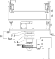
Fig. 1 is the agent structure block diagram (not containing frame, up direction) of the utility model corner facility body embodiment;
Figure 1A is the lateral plan of Fig. 1;
Figure 1B is the other direction block diagram (towards lower direction) of Fig. 1;
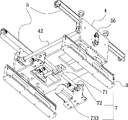
Fig. 2 goes and finds out what's going on for the block diagram that Fig. 1 does not contain base plate;
Fig. 2 A is the lateral plan of Fig. 2;
Fig. 3 is the structural perspective (not containing frame, base plate, lower supporting plate, up direction) of another angle embodiment illustrated in fig. 1;
Fig. 3 A is a corner machine profile block diagram embodiment illustrated in fig. 1;
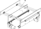
Fig. 4 is the three-dimensional structure diagram (double track structure) of the another embodiment of the utility model corner machine;
Fig. 4 A is the constructional drawing of the straight-through part among Fig. 4 embodiment;
Fig. 4 B is a corner machine profile block diagram embodiment illustrated in fig. 4;
Fig. 5 A is the utility model corner connecting device plan sketch of being used for the specific embodiment one of SMT manufacturing line (being located between two chip mounters and the double track reflow machine);
Fig. 5 B is that the utility model corner connecting device is used for the really plan sketch of the good specific embodiment two (being located between two chip mounters and the single track reflow machine) of SMT manufacturing line;
Fig. 5 C is the utility model corner connecting device plan sketch of being used for the specific embodiment three of SMT manufacturing line (is located between three chip mounters and the double track reflow machine, wherein have the discharging direction of two chip mounters opposed);
Fig. 5 D is the utility model corner connecting device plan sketch of being used for the specific embodiment four of SMT manufacturing line (being located between three chip mounters and the single track reflow machine three same side by side direction dischargings of chip mounter);
Fig. 5 E is the utility model corner connecting device plan sketch of being used for the specific embodiment five of SMT manufacturing line (being located between three chip mounters and the double track reflow machine three same side by side direction dischargings of chip mounter);
Fig. 6 A is the structural representation of plugging into (being used for the double track reflow machine) of SMT manufacturing line of the prior art;
Fig. 6 B is the structural representation of plugging into (being used for the single track reflow machine) of SMT manufacturing line of the prior art.
Description of drawings
1 support, 11 alarm lamps
12 panels, 13 control buttons
2 base plates, 21 rotation position detector switches
22 detector switch adapter plates, 3 lower supporting plates
30 guide rails, 31 live spindles
311 upper fixed seats, 312 shafts
313 carousel supports seats, 314 positioning seats
315 back-up rings 32 detect piece
4 balladeur trains, 41 slide units
42 stirrups, 5 transport sectors
52 power wheels, 53 transmission motors
54 supporting bracket bars, 55 drive spindles
56 chain wheel set, 6 rotating mechanisms
61 rotating machines, 62 synchronous pulleys
63 are with 7 travel mechanisms synchronously
71 nut assemblies, 72 ball screws
73 mobile motor A feed ends
The B1 first discharge end B2 second discharge end
B3 the 3rd discharge end Q1, the Q2 discharging platform of plugging into
The R charging platform S0 corner machine main body of plugging into
The S1 first corner machine S2 second corner machine
The middle platform of plugging into of S3 method of three turning angles machine T
The specific embodiment
In order more to make much of the technology contents of the utility model, below in conjunction with specific embodiment the technical scheme of the utility model is further introduced and explanation, but be not limited to this.
Like Fig. 1 to Fig. 3 A is the specific embodiment accompanying drawing of the monorail structure of the utility model corner machine.A kind of corner machine of the utility model is provided with support 1, also comprise the base plate 2 that connects with support 1, with the rotary lower supporting plate that connects of base plate 23, with the last balladeur train 4 that lower supporting plate 3 sliding types connect, last balladeur train 4 is provided with transport sector 5; Also be installed with the rotating mechanism 6 that is used to drive lower supporting plate 3 rotations on the base plate 2; The transmission direction of transport sector 5 is identical with the direction of slip of last balladeur train 4.Lower supporting plate 3 is connected with to the live spindle that extends below 31, and live spindle 31 is rotary the connection with base plate 2; The upper end of live spindle 31 and lower supporting plate 3 are fixedly connected lower end and rotating mechanism 6 driving coupling through modes such as screws; Rotating mechanism 6 comprises the rotating machine 61 that is fixedly arranged on the base plate 2, be fixedly arranged on the synchronous pulley 62 of live spindle 31 lower ends and connect them and be with 63 synchronously between the two; Transport sector 5 comprises that the transport tape 51 of being located at balladeur train 4 (is provided with two; Be located at the both sides of balladeur train respectively), with the power wheel 52 of transport tape 51 driving coupling (in the practical structures; Constitute by several wheels) and with the transmission motor 53 of power wheel 52 driving coupling (the transmission motor drives two transport tapes simultaneously through drive spindle 55; The other end of drive spindle 55 removes to drive another transport tape through chain wheel set 56); Utilize workpiece such as pcb board can drive moving of another one transport tape simultaneously), below the transport tape 51 of support level, be provided with supporting bracket bar 54.Be provided with travel mechanism 7 between last balladeur train 4 and the lower supporting plate 3.Travel mechanism 7 is ball wire bar pair mechanism (in other embodiment, also can adopt the cylinder power part) in the present embodiment; Ball wire bar pair mechanism comprises the nut assembly 71 that is fixedly arranged on balladeur train 4, is fixedly arranged on the ball screw 72 on the lower supporting plate 3; And with the mobile motor 73 of ball screw 72 driving coupling, mobile motor 73 is fixedly arranged on lower supporting plate 3.Last balladeur train 4 connects with sliding type between the lower supporting plate 3 be linear guides secondary (also can be guide pillar guide pin bushing structure) in the present embodiment in other embodiment; The slide unit 41 (two slide units are arranged on each guide rail) that the linear guides pair comprises the guide rail 30 (two guide rails are arranged) that is fixedly connected with lower supporting plate 3, is fixedly connected with last balladeur train 4.Base plate 2 is provided with rotation position detector switch 21, and lower supporting plate 3 is provided with the detection piece 32 that is used to produce detection signal; Support 1 is the frame of shaped as frame.
Last balladeur train 4 wherein (is the enhancing structural rigidity for the shaped as frame support body that both sides are provided with transport sector 5; Have additional two stirrups 42 in the centre of shaped as frame support body); The lower end of shaped as frame support body and four slide units 41 are fixedly connected; Balladeur train 4 straight line on lower supporting plate 3 is moved, and the moving velocity of last balladeur train 4 and distance are controlled by travel mechanism 7, and the mobile motor 73 in the travel mechanism 7 is stepping motor or servomotor.Lower supporting plate 3 is provided with the shaped as frame plate body of guide rail for both sides.Live spindle 31 wherein is an integral body that is connected into by upper fixed seat 311 and shaft 312; Also be provided with carousel supports seat 313, positioning seat 314 and back-up ring 315, the effect of carousel supports seat 313 is to be connected with base plate through in-to-in thrust baring or conical bearing.Positioning seat 314 passes the bottom that live spindle is connected base plate 2, and plain bearing is equipped with in the inside of positioning seat 314, the phenomenon that makes live spindle 31 off normal can not occur or rock when rotated.Back-up ring 315 passes shaft 312 and is installed in the positioning seat below, withstands positioning seat 315 in-to-in bearings, prevents that bearing from coming off.
Fig. 4 to Fig. 4 B wherein is the corner machine of double rail type structure, and it is on the basis of monorail structure, has increased a straight-though transport sector 5A (i.e. second transport sector).For attractive in appearance, can around the shaped as frame frame of corner machine, add top panel 12, and on panel 12, have additional control button 13.
Shown in Fig. 5 A to Fig. 5 E, be used for the specific embodiment of SMT manufacturing line for a kind of corner connecting device of the utility model.In Fig. 5 B; The corner connecting device is located between a feed end A and two discharge ends (i.e. the second discharge end B1, the second discharge end B2); The position of the first discharge end B1 wherein comprises two corner machines corresponding to feed end A, is respectively the first corner machine S1 and the second corner machine S2; Comprise first corner machine S1 that is located between the first discharge end B1 and the feed end A and the second corner machine S2 that is located at the second discharge end B2, platform T plugs in the middle of being provided with between the first corner machine S1 and the second corner machine S2.Between the first corner machine S1 and feed end A, be provided with the charging platform R that plugs into; Because feed end A is the single track reflow machine, so the charging platform R that plugs into also is the single track platform of plugging into, the first corner machine S1 is the single track corner machine that is provided with the single transport band.
And in Fig. 5 A, the charging platform R that plugs into is the double track platform of plugging into; The first corner machine S1 is the double track corner machine that is provided with two transport tapes, and the frame of double track corner machine is provided with second transport sector, and concrete structure is shown in Fig. 4 to Fig. 4 A.
In Fig. 5 C; Discharge end is three; Comprise the first discharge end B1, the second discharge end B2 and the 3rd discharge end B3, second discharge end B2 wherein and the discharging direction of the 3rd discharge end B3 are opposed, and the second corner machine S2 is located between the second discharge end B2 and the 3rd discharge end B3; The second corner machine S2 is a beidirectional single track corner machine, can plug into to a direction corner from two opposed discharge ends.Between two opposed second discharge end B2, the 3rd discharge end B3 and the second corner machine S2, be respectively equipped with discharging plug into platform Q1, Q2.
In the embodiment of Fig. 5 D and Fig. 5 E, discharge end is three, comprises the first discharge end B1, the second discharge end B2 and the 3rd discharge end B3 that are set up in parallel; The corner machine is three; Be located at the first discharge end B1 the first corner machine S1, be located at the second corner machine S2 of the second discharge end B2, be located at the method for three turning angles machine S3 of the 3rd discharge end B3, wherein the feed end A of Fig. 5 D is the single track reflow machine; In the middle of the first discharge end B1 was located at, the first corner machine S1 was a beidirectional single track corner machine.And in Fig. 5 E, feed end A is the double track reflow machine, and the first discharge end B1 is located at side, and the first corner machine S1 is a double track corner machine.
Among each embodiment of above-mentioned corner connecting device, discharge end is the discharge end of chip mounter, and feed end is the feed end of reflow machine, and reflow machine is double track reflow machine or single track reflow machine; Charging platform, the centre platform of plugging into of plugging into comprises frame and is located at the transport sector of frame, transport sector comprise the transport tape be located on the frame and with the transmission motor of transport tape driving coupling, wherein second transport sector of similar in double track corner machine.
In sum, in the utilization of the utility model corner machine the slip of balladeur train realize between the different transport sectors can angled seamless plugging into.Plug in the centre that the platform structure accomplishes long distance between two corner machines of plugging into, the centre that the utilization of the utility model corner connecting device is provided with transport tape, the platform of plugging into of centre wherein can be parked several workpiece, helps adjusting the process velocity of manufacturing line; Can realize a plurality of discharge ends to a feed end, when being used for the SMT manufacturing line, the discharging of chip mounter that can 2-5 is individual butts up against the charging of a reflow machine; Have energy savings, save labour cost, stable performance; The characteristics of high efficiency help promoting the production quality of product, can adapt to the plugging into of manufacturing line of multiple product; Such as the manufacturing line of various precision components, also can use this corner machine and corner connecting device usually.
The above only further specifies the technology contents of the utility model with embodiment; So that the reader is more readily understood; But do not represent the embodiment of the utility model to only limit to this, any technology of doing according to the utility model is extended or recreation, all receives the protection of the utility model.The protection domain of the utility model is as the criterion with claims.
Claims (10)
1. a corner machine is provided with support, it is characterized in that also comprising the base plate that connects with support, with the rotary lower supporting plate that connects of base plate, the last balladeur train that connects with the lower supporting plate sliding type, the described balladeur train of going up is provided with transport sector; Also be installed with the rotating mechanism that is used to drive the lower supporting plate rotation on the described base plate; The transmission direction of said transport sector is identical with the direction of slip of last balladeur train.
2. corner machine according to claim 1 is characterized in that said lower supporting plate is connected with to the live spindle that extends below, and described live spindle is rotary the connection with base plate; The upper end of said live spindle connects with lower supporting plate, lower end and rotating mechanism driving coupling; Described rotating mechanism comprises the rotating machine that is fixedly arranged on the base plate, the synchronous pulley that is fixedly arranged on the live spindle lower end and is with synchronously; Described transport sector comprise the transport tape of being located at balladeur train, with the power wheel of transport tape driving coupling and with the transmission motor of power wheel driving coupling; Described going up between balladeur train and the lower supporting plate is provided with travel mechanism.
3. corner machine according to claim 2; It is characterized in that described travel mechanism is ball wire bar pair mechanism or cylinder power part; Described ball wire bar pair mechanism comprises the nut assembly that is fixedly arranged on balladeur train, is fixedly arranged on the ball screw on the lower supporting plate; And with the mobile motor of ball screw driving coupling, described mobile motor is fixedly arranged on lower supporting plate.
4. corner machine according to claim 3 is characterized in that it is linear guides pair or guide pillar guide pin bushing structure that described upward balladeur train connects with the sliding type of lower supporting plate; The slide unit that described linear guides pair comprises the guide rail that is fixedly connected with lower supporting plate, is fixedly connected with last balladeur train.
5. corner machine according to claim 4 is characterized in that described base plate is provided with rotation position detector switch, and described lower supporting plate is provided with the detection piece that is used to produce detection signal; Described support is the frame of shaped as frame.
6. corner connecting device; Be located between a feed end and at least two discharge ends; The position of first discharge end wherein is characterized in that comprising each described corner machine of claim 1 to 5 corresponding to feed end, and described corner machine is at least two; Comprise first corner machine of being located between first discharge end and the feed end and the second corner machine of being located at second discharge end, the platform of plugging in the middle of being provided with between the described first corner machine and the second corner machine.
7. corner connecting device according to claim 6 is characterized in that being provided with between described first corner machine and the feed end charging platform of plugging into; The described charging platform of plugging into is single track platform or the double track platform of plugging into of plugging into; The described first corner machine is the double track corner machine that is provided with the single track corner machine of single transport band or is provided with two transport tapes, and the frame of said double track corner machine is provided with second transport sector.
8. corner connecting device according to claim 7 is characterized in that described discharge end is three, and second discharge end and the 3rd discharge end are opposed, and the second corner machine is located between second discharge end and the 3rd discharge end.
9. corner connecting device according to claim 7; It is characterized in that described discharge end is three, described corner machine is three, and first discharge end, second discharge end and the 3rd discharge end are set up in parallel; The second corner machine is located at second discharge end, and method of three turning angles machine is located at the 3rd discharge end.
10. corner connecting device according to claim 9 is characterized in that described discharge end is the discharge end of chip mounter, and described feed end is the feed end of reflow machine, and described reflow machine is double track reflow machine or single track reflow machine; Described charging platform, the centre platform of plugging into of plugging into comprises frame and is located at the transport sector of frame, described transport sector comprise the transport tape be located on the frame and with the transmission motor of transport tape driving coupling.
Priority Applications (1)
| Application Number | Priority Date | Filing Date | Title |
|---|---|---|---|
| CN 201120133185 CN202116025U (en) | 2011-04-29 | 2011-04-29 | Angle turning machine and connecting device constituted by angle turning machine |
Applications Claiming Priority (1)
| Application Number | Priority Date | Filing Date | Title |
|---|---|---|---|
| CN 201120133185 CN202116025U (en) | 2011-04-29 | 2011-04-29 | Angle turning machine and connecting device constituted by angle turning machine |
Publications (1)
| Publication Number | Publication Date |
|---|---|
| CN202116025U true CN202116025U (en) | 2012-01-18 |
Family
ID=45457109
Family Applications (1)
| Application Number | Title | Priority Date | Filing Date |
|---|---|---|---|
| CN 201120133185 Expired - Lifetime CN202116025U (en) | 2011-04-29 | 2011-04-29 | Angle turning machine and connecting device constituted by angle turning machine |
Country Status (1)
| Country | Link |
|---|---|
| CN (1) | CN202116025U (en) |
Cited By (11)
| Publication number | Priority date | Publication date | Assignee | Title |
|---|---|---|---|---|
| CN104495319A (en) * | 2014-12-22 | 2015-04-08 | 苏州博众精工科技有限公司 | Assembly line mechanism capable of changing between left and right directions |
| WO2015070432A1 (en) * | 2013-11-15 | 2015-05-21 | 王健 | Automatic board-receiving apparatus |
| WO2015070433A1 (en) * | 2013-11-15 | 2015-05-21 | 王健 | Pcb buffer apparatus |
| CN104649064A (en) * | 2014-12-31 | 2015-05-27 | 东莞市科立电子设备有限公司 | Whole-line online double-spindle plate separator |
| CN104960892A (en) * | 2015-07-01 | 2015-10-07 | 吴中区横泾博尔机械厂 | Loading mechanism for automatic electric material press-mounting machine |
| CN105314384A (en) * | 2015-11-30 | 2016-02-10 | 苏州康贝尔电子设备有限公司 | Turning machine |
| CN105398799A (en) * | 2015-12-30 | 2016-03-16 | 苏州博众精工科技有限公司 | Transport assembly |
| CN106335758A (en) * | 2016-08-27 | 2017-01-18 | 深圳市尚宏自动化设备有限公司 | Multi-wire-in-one translation machine |
| CN109018830A (en) * | 2018-08-14 | 2018-12-18 | 珠海锐翔智能科技有限公司 | A kind of plug into discharging device and its working method of lifting reflux |
| CN112320216A (en) * | 2020-10-13 | 2021-02-05 | 苏州象平自动化科技有限公司 | Full-automatic two-in-one board separator |
| CN112490160A (en) * | 2020-12-23 | 2021-03-12 | 深圳新益昌科技股份有限公司 | Semiconductor packaging all-in-one machine |
-
2011
- 2011-04-29 CN CN 201120133185 patent/CN202116025U/en not_active Expired - Lifetime
Cited By (15)
| Publication number | Priority date | Publication date | Assignee | Title |
|---|---|---|---|---|
| WO2015070432A1 (en) * | 2013-11-15 | 2015-05-21 | 王健 | Automatic board-receiving apparatus |
| WO2015070433A1 (en) * | 2013-11-15 | 2015-05-21 | 王健 | Pcb buffer apparatus |
| CN104495319B (en) * | 2014-12-22 | 2016-07-20 | 苏州博众精工科技有限公司 | One left and right reversed flow waterline mechanism |
| CN104495319A (en) * | 2014-12-22 | 2015-04-08 | 苏州博众精工科技有限公司 | Assembly line mechanism capable of changing between left and right directions |
| CN104649064B (en) * | 2014-12-31 | 2018-02-23 | 东莞市科立电子设备有限公司 | A kind of online double main shaft board separators of whole line |
| CN104649064A (en) * | 2014-12-31 | 2015-05-27 | 东莞市科立电子设备有限公司 | Whole-line online double-spindle plate separator |
| CN104960892A (en) * | 2015-07-01 | 2015-10-07 | 吴中区横泾博尔机械厂 | Loading mechanism for automatic electric material press-mounting machine |
| CN105314384A (en) * | 2015-11-30 | 2016-02-10 | 苏州康贝尔电子设备有限公司 | Turning machine |
| CN105398799A (en) * | 2015-12-30 | 2016-03-16 | 苏州博众精工科技有限公司 | Transport assembly |
| CN106335758A (en) * | 2016-08-27 | 2017-01-18 | 深圳市尚宏自动化设备有限公司 | Multi-wire-in-one translation machine |
| CN109018830A (en) * | 2018-08-14 | 2018-12-18 | 珠海锐翔智能科技有限公司 | A kind of plug into discharging device and its working method of lifting reflux |
| CN109018830B (en) * | 2018-08-14 | 2023-10-03 | 珠海锐翔智能科技有限公司 | Lifting reflux connection discharging device and working method thereof |
| CN112320216A (en) * | 2020-10-13 | 2021-02-05 | 苏州象平自动化科技有限公司 | Full-automatic two-in-one board separator |
| CN112490160A (en) * | 2020-12-23 | 2021-03-12 | 深圳新益昌科技股份有限公司 | Semiconductor packaging all-in-one machine |
| CN112490160B (en) * | 2020-12-23 | 2021-08-03 | 深圳新益昌科技股份有限公司 | Semiconductor packaging all-in-one machine |
Similar Documents
| Publication | Publication Date | Title |
|---|---|---|
| CN202116025U (en) | Angle turning machine and connecting device constituted by angle turning machine | |
| CN207606800U (en) | A kind of vertical machine of novel H profile steel group | |
| CN108907745A (en) | A kind of copper bus-bar process units with Combined production line | |
| CN203343671U (en) | Automobile welding production device with cross-shaped sliding table | |
| CN208773562U (en) | Seven axis efficient electric slide units | |
| CN202573243U (en) | Automatic turnover platform component and bedplate printing equipment | |
| CN110921204B (en) | Be used for TBM to connect belt feeder slag output system bracket device | |
| CN203222307U (en) | Device for guiding and positioning conveying and carrying jig | |
| CN204777464U (en) | A novelly thoughtlessly go out arrange anode machine for photovoltaic cell assembly line | |
| CN111747088A (en) | Double-layer electric plate turnover device | |
| CN202207838U (en) | Novel feeding device for sawing machine | |
| CN202815591U (en) | Profiling traveling device | |
| CN205896074U (en) | Ball screw transmission mechanism suitable for portable contact net transmission system | |
| CN209905845U (en) | Double-layer electric plate turnover device | |
| CN211254043U (en) | Long-distance suspension type annular chain mechanism | |
| CN208759005U (en) | A kind of copper bus-bar process units with Combined production line | |
| CN211250520U (en) | Guide rail device of double-end edge bonding machine | |
| CN210762965U (en) | High-stability corner machine | |
| CN203473890U (en) | Slab rubber turning device | |
| CN203247403U (en) | Motion structure of machine table | |
| CN206493512U (en) | A kind of clipping type frothing clamp transmission device | |
| CN106586429B (en) | Novel full-automatic assembly line of multistation | |
| CN220264059U (en) | Circulation line of double-sided track of single bottom plate | |
| CN217147463U (en) | Double-track intelligent annular motion platform | |
| CN216218568U (en) | Multimedia sound circuit board mounting device |
Legal Events
| Date | Code | Title | Description |
|---|---|---|---|
| C14 | Grant of patent or utility model | ||
| GR01 | Patent grant | ||
| CX01 | Expiry of patent term |
Granted publication date: 20120118 |
|
| CX01 | Expiry of patent term |