CN202090465U - Wall body structure - Google Patents
Wall body structure Download PDFInfo
- Publication number
- CN202090465U CN202090465U CN201020175870XU CN201020175870U CN202090465U CN 202090465 U CN202090465 U CN 202090465U CN 201020175870X U CN201020175870X U CN 201020175870XU CN 201020175870 U CN201020175870 U CN 201020175870U CN 202090465 U CN202090465 U CN 202090465U
- Authority
- CN
- China
- Prior art keywords
- link plate
- wall body
- load
- body structure
- connector
- Prior art date
- Legal status (The legal status is an assumption and is not a legal conclusion. Google has not performed a legal analysis and makes no representation as to the accuracy of the status listed.)
- Expired - Lifetime
Links
Images


Abstract
A wall body structure comprises at least two load-bearing columns, an inner-side hanging board, an outer-side hanging board and a heat-insulating material, wherein the load-bearing columns are vertically arranged on the ground at intervals; the inner-side hanging board is positioned on the inner sides of the load-bearing columns; the outer-side hanging board is positioned on the outer sides of the load-bearing columns; and the heat-insulating material is filled in space formed among the load-bearing columns, the inner-side hanging board and the outer-side hanging board. The wall body structure provided by the utility model is relatively simple, the building process is simple and convenient, and the better heat-insulating effect can be obtained.
Description
Technical field
The utility model relates to the engineering construction field, more particularly, relates to a kind of wall body structure with heat insulation function.
Background technology
Along with the raising of people to the building energy-saving environmental requirement, increasing building need make up insulated wall.
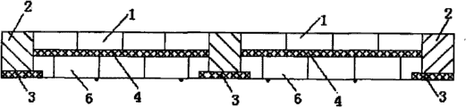
China utility model patent CN 201268902 Y disclose a kind of laminated heat-preserving wall body structure, as shown in Figure 1 to Figure 3, the technical scheme of described laminated heat-preserving wall body structure is: be provided with warming plate 4 between beam 7, the post 2, be respectively arranged with building block 1 and building block 6 in the inside and outside both sides of this warming plate 4, warming plate 3 is sticked in the outside at beam 7 and post 2, and cable wire 5 is fixedly hung in the building block outside between beam 7 and post 2.
Yet the defective of above-mentioned laminated heat-preserving wall body structure is owing to piling up in the inside and outside both sides of warming plate 4 building block 1 and 6 are arranged, thereby above-mentioned wall body structure need carry out a large amount of work of piling up at the scene when making up, and the consumption worker is consuming time.And on the width of above-mentioned wall body structure, warming plate 4 is extremely thin with respect to building block 1 and 6 thickness, thereby the heat insulation effect of this laminated heat-preserving wall body structure is comparatively limited.
The utility model content
The purpose of this utility model is to overcome the defective that structure efficient is lower and heat insulation effect is limited of above-mentioned traditional laminated heat-preserving wall body structure, and provides a kind of efficient that makes up higher and have a wall body structure of heat insulation effect preferably.
According to an aspect of the present utility model, a kind of wall body structure is provided, this wall body structure comprises: at least two load-bearing pillars, these at least two load-bearing pillars are vertically set up on the ground at each interval; Inboard link plate, this inboard link plate is positioned at the inboard of described load-bearing pillar; Outside link plate, this outside link plate is positioned at the outside of described load-bearing pillar, and described inboard link plate all is connected with described load-bearing pillar with outside link plate; And heat insulating material, in the space of described filled thermal insulation materials between described load-bearing pillar, inboard link plate and outside link plate.
According to above-mentioned wall body structure provided by the utility model, can in advance inboard link plate and outside link plate manufacturing be finished, inboard link plate and outside link plate after then manufacturing being finished are transported to the job site.Then, simply inboard link plate and outside link plate are connected respectively on the described load-bearing pillar, thereby the structure of formation hollow arrives filled thermal insulation materials in the space between inboard link plate, outside link plate and the load-bearing pillar then.
By above description as can be known, wall body structure provided by the utility model is simple relatively, can finish the structure to wall body structure at the construction field (site) within a short period of time, and it is higher to make up efficient.And the thickness of inboard link plate and outside link plate is compared relative thinner with the thickness of heat insulating material, thereby can obtain thicker heat insulating material, and then can obtain heat insulation effect preferably.
Description of drawings
Fig. 1 to Fig. 3 is the schematic diagram of the disclosed laminated heat-preserving wall body structure of CN 201268902 Y;
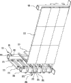
Fig. 4 is the stereogram according to the wall body structure of a kind of preferred implementation of the utility model;
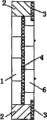
Fig. 5 is the elevation of wall body structure shown in Fig. 4;
Fig. 6 is the vertical view of wall body structure shown in Fig. 4;
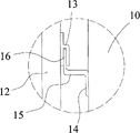
The circle zoomed-in view partly that Fig. 7 represents for dotted line among Fig. 4;
Fig. 8 is the zoomed-in view of the wall body structure of another embodiment of the utility model in described circle part.
The specific embodiment
Below with reference to accompanying drawing the specific embodiment of the present utility model is described in detail.
, comprise to shown in Figure 6 as Fig. 4 according to wall body structure of the present utility model:
At least two load-bearing pillars 10, these many load-bearing pillars 10 are vertically set up on the ground at each interval;
Outside link plate 12, this outside link plate 12 is positioned at the outside of described load-bearing pillar 10, described inboard link plate 11 all is connected with described load-bearing pillar 10 with outside link plate 12, thereby makes inboard link plate 11 constitute the medial surface of described wall body structure, and outside link plate 12 constitutes the lateral surface of described wall body structure; And
The heat insulating material (not shown) is in the space of described filled thermal insulation materials between described load-bearing pillar 10, inboard link plate 11 and outside link plate 12.
Load-bearing pillar 10 is vertically set up on the ground, here the explanation of relative broad range should be done in so-called ground, promptly this ground not only comprises the earth (the big ground that load-bearing pillar 10 can directly be set up), also comprises any building foundation, as the ground of any one deck in the highrise building building.Load-bearing pillar 10 can be set up on the ground in several ways, as burying underground in advance, piles up on the ground and forms etc., can also be on the ground direct welded steel pipe and form load-bearing pillar 10.The main effect of load-bearing pillar 10 is to support and the carrying gravitational load, thereby load-bearing pillar 10 has higher structural strength usually.
Though the load-bearing pillar 10 shown in Fig. 4 has 3, also can there be 4 or more a plurality of.Load-bearing pillar 10 can be various forms of load-bearing pillars, as encased structures or steel work.The cross sectional shape of load-bearing pillar 10 can be for the shape of any appropriate, as polygon.For the ease of being connected with inboard link plate 11 and outside link plate 12 (directly or indirectly), the cross sectional shape of load-bearing pillar 10 is a rectangle, as shown in Figure 4 but preferably.
The application scenario of the wall body structure that the utility model is related includes but not limited to: thus utilize at least two load-bearing pillars 10 and inboard link plate and outside link plate to form wall body structure, so that the inner space of building is separated.
And, be connected inboard link plate 11 and outside link plate 12 on the load-bearing pillar 10 after, promptly form the space that holds insulation layer, filled thermal insulation materials can be made described wall body structure to this space.Thereby this building process technology is simple, easy to operate, can improve the structure efficient that makes up body of wall too.
The bottom in the space that forms between inboard link plate 11, outside link plate 12 and two load-bearing pillars 10 can be ground, perhaps the lower seals (not shown) can also be set in addition, leak from the bottom of inboard link plate 11 and outside link plate 12 to prevent heat insulating material.And the top in described space can also can preferably be provided with the top cover (not shown), so that described space sealing is got up for what open.These can be selected according to concrete application scenario.
But in order more reliably and securely described link plate (comprising inboard link plate 11 and outside link plate 12) to be connected on the load-bearing pillar 10, preferably, described wall body structure also comprises connector, and inboard link plate 11 and outside link plate 12 are fixed on the load-bearing pillar 10 by described connector.
For example, connector can be securing member (as bolt, screw or rivet), by the securing member as connector inboard link plate 11 and outside link plate 12 is connected on the load-bearing pillar 10; Described connector can also be for being arranged on a plurality of projectioies on the described link plate, and load-bearing pillar 10 is provided with a plurality of corresponding concave part simultaneously, will insert in the load-bearing pillar 10 as the projection of connector then, is connected with the assembling of load-bearing pillar to realize described link plate.
For the ease of realizing the assembling of described link plate and load-bearing pillar 10, preferably, described connector comprises a plurality of first connectors that are fixedly installed on inboard link plate 11 and the outside link plate 12, and being arranged on a plurality of second connectors on the load-bearing pillar 10, described first connector can cooperatively interact with described second connector.By first connector and second connector that cooperatively interacts, realize reliable connection the between described link plate and the load-bearing pillar.
Described first connector is arranged on inboard link plate 11 and the outside link plate 12, be specially be arranged on inboard link plate 11 and outside link plate 12 after being assemblied in load-bearing pillar on the surface of wall body structure inside.And second connector is arranged on the load-bearing pillar 10, cooperatively interacts by making first connector and second connector, thereby described link plate can be installed on the load-bearing pillar 10.
Described first connector and second connector can have various ways, as long as be convenient to realize the matching relationship of first connector and second connector.
For example, extremely shown in Figure 8 as Fig. 4, preferably by Fig. 7 and shown in Figure 8, described first connector is a h shape part 13, this h shape part 13 be arranged on inboard link plate 11 and the outside link plate 12 and the opening of this h shape part 13 down, at least a portion of described second connector is inserted the opening of described h shape part from the below, thereby utilizes the opening of h shape part 13 that described link plate is hung on described second connector.
Though first connector is a h shape part in the accompanying drawings, the utility model is not limited to this kind concrete form.For example, first connector can be for having the parts of blind hole, and this blind hole is inserted in this blind hole by the bar that makes second connector down, can realize the matching relationship between first connector and second connector equally.
As mentioned above, first connector is a plurality of, and these a plurality of first connectors are arranged on inboard link plate 11 and the outside link plate 12.Since first connector need with load-bearing pillar 10 is set on corresponding second connector match, thereby first connector and second connector also need to have locational corresponding relation, guaranteeing that each first connector all matches with corresponding second connector, thereby make the reliable and firm matching relationship of realization between described suspension member and the load-bearing pillar.
Second connector is arranged on the load-bearing pillar 10, this second connector has various ways equally, and for example, described second connector comprises: the first angle bar spare 17, this first angle bar spare 17 comprises fixed edge 18 and support edge 19, and described fixed edge 18 (fixing) is fitted on the load-bearing pillar 10; The second angle bar spare 20, this second angle bar spare 20 comprises fillet 21 and outstanding limit 22, described fillet 21 is fixedlyed connected with support edge 19, the fixed edge 18 parallel to each other and spaces of described outstanding limit 22 and the described first angle bar spare 17, should project upwards and insert in the opening of described h shape part 13, in outstanding limit 22 as Fig. 4 and shown in Figure 7.
For first connector with h shape part 13 cooperates, second connector comprises the first angle bar spare 17 that is arranged on each load-bearing pillar 10, and this first angle bar spare is a plurality of (as shown in Figure 4), and the first angle bar spare 17 is for being horizontally disposed with.The fixed edge 18 of the first angle bar spare 17 fixedly is fitted on the load-bearing pillar 10, and support edge 19 then stretches out perpendicular to the side of load-bearing pillar 10, is used to provide support the surface.
The second angle bar spare 20 comprises fillet 21 and outstanding limit 22, and this fillet 21 is fixedly connected on the support edge 19 of the described first angle bar spare 17.Specifically, one end of one second angle bar spare 20 is connected on the support edge 19 of one the first angle bar spare 17 that is positioned at a load-bearing pillar 10, and the other end of this second angle bar spare 20 is connected on the support edge 19 of the first angle bar spare 17 of a correspondence that is positioned at another load-bearing pillar 10.
Simultaneously, the outstanding limit 22 of the second angle bar spare 20 projects upwards from fillet 21, so that insert in the opening of h shape part 13, thereby realizes being connected between first connector and second connector.
Though in manual, be described as " angle bar spare ", but it is iron that the angle bar spare here is not limited to material, and the material of described angle bar spare can be various metal material (as aluminium, steel, copper etc.) and/or the nonmetals (as various engineering plastics etc.) that are suitable for being applied to technical solutions of the utility model.
As the selectable mode of another kind, described connector can comprise the basal part 14 that is fitted on the load-bearing pillar 10, from the support portion 15 that this basal part 14 extends perpendicular to basal part 14, and from the support portion 15 perpendicular to these support portion 15 upwardly extending lug bosses 16, this lug boss 16 inserts in the opening of h shape part 13, as shown in Figure 7.
In fact, from cross sectional shape, the assembly of the first angle bar spare 17 shown in second connector shown in Fig. 8 and Fig. 7 and the second angle bar spare 20 is comparatively similar, no longer second connector shown in Fig. 8 is done describing in detail here.
In addition, described second connector can also be H shaped steel, and a side of this H shaped steel can be inserted among the opening as the h shape part 13 of first connector.
In above-mentioned connected mode, so-called fixedly connected both can be dismountable fixedly connected (for example) by bolt connection etc., also can be non-removable fixedly connected (as welding, bonding or riveted joint etc.).Selected according to concrete application scenario.But preferably, said fixing connects (as fixedlying connected between the first angle bar spare 17 and the second angle bar spare 20, fixedlying connected etc. between the first angle bar spare 17 and the load-bearing pillar 10) for dismountable fixedly connected, thereby convenient to wall body structure dismantle, I﹠ M, can also be convenient to the heat insulating material in the wall body structure is replenished.
And, the described wall body structure that utilizes above-mentioned mechanical connection manner to form, structural strength is higher, has higher shock resistance.
According to a kind of embodiment of the present utility model, described wall body structure forms stalk, and adjacent described inboard link plate 11 is adjacent to each other, and adjacent described outside link plate 12 is adjacent to each other.
That is to say that a plurality of load-bearing pillars 10 that form this stalk are arranged as straight line, a plurality of load-bearing pillars 10 according to being arranged as straight line can form stalk.And described inboard link plate 11 and outside link plate 12 be adjacency successively all, thereby constitutes the medial surface and the lateral surface of this stalk.
In this embodiment, second connector that is arranged on each load-bearing pillar 10 has multiple set-up mode.For example, for each second connector (H shaped steel, the first angle bar spare and the second angle bar spare as described), each second connector only can be arranged on the corresponding load-bearing pillar 10, promptly company's part does not stride across two different load-bearing pillars 10.Thereby, for this form, described link plate can only with load-bearing pillar 10 equitant parts on cooperatively interact by h shape part 13 and second connector that is arranged on the load-bearing pillar 10.
For another example, for each second connector, second connector can stride across two different load-bearing pillars 10 and horizontal-extending is connected on a plurality of load-bearing pillars 10.Thereby, for this form, except with load-bearing pillar 10 equitant parts on, described link plate can also cooperatively interact by the h shape part 13 and second connector on the part between the adjacent load-bearing pillar 10, thereby obtains more reliable and firm support.
According to another kind of embodiment of the present utility model, as Fig. 4 and shown in Figure 6, described wall body structure comprises two stalks that form the turning each other at least, on each stalk, each second connector all is a horizontal-extending and on a plurality of load-bearing pillars 10 of being connected to, adjacent described inboard link plate 11 is adjacent to each other, adjacent described outside link plate 12 is adjacent to each other, and around the corner, adjacent described inboard link plate 11 is (directly or indirectly) adjacency each other, and adjacent outside link plate 12 also is (directly or indirectly) adjacency each other.
The difference part of the wall body structure of described wall body structure with turning and stalk mainly is the structure of corner.Specifically, around the corner, the inboard link plate 11 that belongs to two stalks respectively can not cover on the load-bearing pillar 10 that is positioned at corner simultaneously, otherwise will occur interfering.
For this reason, on each stalk, each second connector all is a horizontal-extending and on a plurality of load-bearing pillars 10 of being connected to.Therefore, described link plate (especially inboard link plate 11) can also cooperatively interact by the h shape part 13 and second connector on the part between the adjacent load-bearing pillar 10, thereby obtains more reliable and firm support.
Similarly, for each stalk, described inboard link plate 11 and outside link plate 12 be adjacency successively all, thereby constitutes the medial surface and the lateral surface of this stalk.And around the corner, adjacent described inboard link plate 11 is adjacent to each other, and adjacent outside link plate 12 also is adjacent to each other, and leaks by the slit between the link plate to prevent inner heat insulating material.
Around the corner, adjacent (belong to respectively different two sections stalks) inboard link plate 11 is adjacency directly, perhaps can also connect indirectly by being fixed on the turning shape plate on the described load-bearing pillar.For the outside link plate 12 that is positioned at the turning also is so, both can directly connect, and also can connect indirectly by turning shape plate, as long as prevent to form the slit between adjacent link plate.
Described turning can be selected according to concrete structural parameters, and to 150 degree, preferably, described turning is the right angle as 60 degree, i.e. 90 degree.
After the assembling of finishing described wall body structure, described inboard link plate 11 and outside link plate 12 form the both sides of described wall body structure.If do not need wall body structure is fitted up, then inboard link plate 11 and outside link plate 12 can be tabula rasa.
Yet for requiring wall body structure to have in the higher ornamental occasion, preferably, the surface of inboard link plate 11 and/or outside link plate 12 is provided with decorative pattern.Thereby, finish after the assembling of described wall body structure, do not need again described link plate to be carried out any decoration, and directly form the wall body structure that meets ornamental requirement.
Consider the fire protection requirement of building, preferably, described inboard link plate 11 and/or outside link plate 12 are made by refractory material, for example can also be the compound link plate of these materials and light material for stone material, concrete, pottery or glass etc.
Owing between described link plate, be provided with heat insulating material, in order to prevent that as much as possible extraneous moisture or aqueous vapor from entering in the heat insulating material, and the heat insulation effect of heat insulating material is descended, preferably, inboard link plate 11 and/or outside link plate 12 comprise stacked pervious layer and impervious layer, and this impervious layer directly contacts with described heat insulating material.
Specifically, as the water conservation layer, promptly this pervious layer can absorb certain moisture to pervious layer, thereby makes the space that is limited by above-mentioned wall body structure have the effect of preserving moisture in fact, and especially the link plate as the wall body structure inboard preferably is provided with pervious layer.And impervious layer can guarantee that the inside of wall body structure keeps dry, to prevent the heat insulation effect generation harmful effect to the heat insulating material of wall body structure inside.Link plate as the wall body structure outside is provided with pervious layer, thereby can keep or absorb certain moisture, so that the temperature in the space that whole wall body structure limited can be very not high, in weather in summer season of heat, this cooling-down effect is particularly evident.
Described inboard link plate 11 and/or outside link plate 12 can be spliced for monolithic or polylith, and as shown in Figure 5, outside link plate 12 comprises a plurality of link plates unit 12 ' of a plurality of mutual splicings.This can be according to the size of link plate and application scenario thereof and is selected.
The heat insulating material in the space between described load-bearing pillar 10, inboard link plate 11 and outside link plate 12 can be various heat insulating materials commonly used, as asbestos etc.
But preferably, described heat insulating material is one or more inorganic lightweight material and/or the inorganic-organic composite light material that comprises in foam cement, granular polystyrene, mineral wool, haydite concrete, perlite, the expanded vermiculite concrete.These materials have relatively long application life, thereby this heat insulating material has and integral wall structure much the same substantially application life, thereby can continue to maintain good heat insulation effect in the use of wall body structure.
And described heat insulating material is preferably refractory material and makes, thereby improves the fire resistance rating of wall body structure.
Preferably, in order to reduce the overall weight of wall body structure, described wall body structure also comprises a plurality of hollow tubes, and these a plurality of hollow tubes are fixed in the space between described load-bearing pillar 10, inboard link plate 11 and the outside link plate 12, and is surrounded by described heat insulating material.
Described hollow tube can be various pipe fittings, as the steel pipe of hollow, and perhaps mao bamboon etc.Described a plurality of hollow tube can be arranged in the space between described load-bearing pillar 10, inboard link plate 11 and the outside link plate 12 abreast, and is fixedly connected on described load-bearing pillar and/or described link plate.
By hollow tube is set, the overall weight of wall body structure is reduced, can reduce the consumption of heat insulating material, and hollow tube also helps the insulation and the heat-blocking action of wall body structure.
Wall body structure provided by the utility model combines described link plate and the heat insulating material between link plate, realizes the effect of insulation, heat insulation, sound-absorbing on the whole.And, can also be at the enterprising luggage of link plate decorations, thus can realize the decorative effect of wall body structure simultaneously.
More than the critical piece and the annexation thereof of wall body structure provided by the utility model described in detail.Be described below in conjunction with the building process of accompanying drawing this wall body structure.
The building process of described wall body structure can comprise the steps:
(1) vertically sets up at least two load-bearing pillars 10 of each interval on the ground;
(2) inboard link plate 11 and outside link plate 12 are connected in described load-bearing pillar 10, described inboard link plate 11 is positioned at the inboard of described load-bearing pillar 10, and described outside link plate 12 is positioned at the outside of described load-bearing pillar 10; And
(3) with in the space of filled thermal insulation materials between described load-bearing pillar 10, inboard link plate 11 and outside link plate 12.
As mentioned above, when making up wall body structure provided by the utility model, at first set up at least two load-bearing pillars 10, for example set up described load-bearing pillar 10 by piling up, weld methods such as steel column in predetermined place.
Above-mentioned construction process is fairly simple, after being connected respectively to inboard link plate 11 and outside link plate 12 on the load-bearing pillar 10, make inboard link plate 11 constitute the medial surface of wall body structure, and outside link plate 12 constitutes the lateral surface of wall body structure, will get final product in the space of filled thermal insulation materials between described load-bearing pillar 10, inboard link plate 11 and outside link plate 12 then.
Owing to need not pile up operation, but realize wall body structure, thereby it is higher to make up efficient by simple assembling process in the heat insulating material both sides.In addition, the thickness of inboard link plate 11 and outside link plate 12 is relative thinner, thereby can make that the thickness of heat insulating material is thicker, thereby obtains heat insulation effect preferably.And, utilize load-bearing pillar 10 to realize the load capacity of whole wall body structure, also make wall body structure have higher structural strength and stability.
As mentioned above, described link plate can be realized and being connected of load-bearing pillar 10 in several ways, as bonding, joggle etc.In step (2), on described inboard link plate 11 and outside link plate 12, first connector is set, on described load-bearing pillar 10, second connector is set, by described first connector and described second connector being cooperatively interacted and inboard link plate 11 and outside link plate 12 being connected in described load-bearing pillar 10.
Utilize the assembly relation of this first connector and second connector, can realize between described link plate and the load-bearing pillar fast and assembling reliably be connected.Described connector can be various securing members (as bolt, screw or rivet).Described first connector and second connector can have various ways, as long as be convenient to realize the matching relationship of first connector and second connector.
In addition, in step (1), described load-bearing pillar 10 is arranged on the same straight line, thereby makes described wall body structure form stalk; In step (2), adjacent described inboard link plate 11 is adjacent to each other and adjacent described outside link plate 12 is adjacent to each other.
That is to say that when setting up described a plurality of load-bearing pillar 10 in the job location, the line of the position that each load-bearing pillar 10 is set up is a straight line, thereby the wall body structure that makes up according to these a plurality of load-bearing pillars 10 is the stalk structure naturally.The stalk structure is generally used for a space is divided into predetermined two parts, i.e. the inside part of wall body structure and Outboard Sections.
For the stalk structure, in the step that second connector is set, second connector can have different set-up modes.For example, on described load-bearing pillar 10, be provided with in the step of second connector, each second connector only be arranged on the load-bearing pillar 10 of a correspondence.If each second connector only is arranged on the load-bearing pillar 10 of a correspondence, then described link plate can only with load-bearing pillar 10 equitant parts on cooperatively interact by h shape part 13 and second connector that is arranged on the load-bearing pillar 10.
In addition, can also make each second connector horizontal-extending and be connected on a plurality of load-bearing pillars 10.Then for this form, except with load-bearing pillar 10 equitant parts on, described link plate can also cooperatively interact by the h shape part 13 and second connector on the part between the adjacent load-bearing pillar 10, thereby obtains more reliable and firm support.
In addition, in step (1), described load-bearing pillar 10 can not be arranged on the same straight line, thereby described wall body structure is comprised at least form each other two stalks at turning, for each stalk, be provided with in the step of second connector on described load-bearing pillar 10, making each second connector all is horizontal-extending and on a plurality of load-bearing pillars 10 of being connected to; In step (2), adjacent described inboard link plate 11 is adjacent to each other and adjacent described outside link plate 12 is adjacent to each other, and around the corner, adjacent described inboard link plate 11 and outside link plate 12 also is adjacent to each other.
For this kind situation, on each stalk, each second connector all is a horizontal-extending and on a plurality of load-bearing pillars 10 of being connected to.Therefore, described link plate (especially inboard link plate 11) can also cooperatively interact by the h shape part 13 and second connector on the part between the adjacent load-bearing pillar 10, the defective that will occur interfering, and obtain more reliable and firm support thereby if the inboard link plate 11 of avoiding belonging to respectively two stalks covers on the load-bearing pillar 10 that is positioned at corner around the corner simultaneously.
In order to make the described link plate of described wall body structure one fit on just can have the effect of decoration, preferably, also be included in described inboard link plate 11 and outside link plate 12 are connected in before the described load-bearing pillar 10, described inboard link plate 11 and outside link plate 12 are decorated.
Therefore, inboard link plate 11 and outside link plate 12 that assembling is connected on the described load-bearing pillar 10 all are to have finished fitting-up, need not again the wall body structure of finishing assembling to be carried out extra fitment operation, thereby both improved the aesthetic property of wall body structure, also improved the structure efficient of wall body structure.
And, in step (3) before, a plurality of hollow tubes can also be arranged in the space between described load-bearing pillar 10, inboard link plate 11 and the outside link plate 12.
For example, a plurality of hollow tubes erectly can be fixedly installed on the ground, also a plurality of hollow tubes laterally can be arranged between two adjacent load-bearing pillars 10.Because hollow tube has occupied the space of waiting to hold heat insulating material, thereby can reduce the consumption of heat insulating material, and hollow tube also helps the insulation and the heat-blocking action of wall body structure.Described hollow tube can be various pipe fittings, as the steel pipe of hollow, and perhaps mao bamboon etc.
The building process of wall body structure provided by the utility model and wall body structure has above been described in conjunction with embodiment of the present utility model, and, the feature of above-mentioned wall body structure can make up each other in any suitable manner, arrange in pairs or groups, thus other embodiments that acquisition is not described in this manual.In addition, this manual should be considered as descriptive or indicative, rather than to the restriction of the application's protection domain.And disclosed each feature is not limited to the adduction relationship of each claim in claims in this manual, but can combine separately and/or in combination in any suitable manner, thereby can make various modifications, replacement and variation.
Claims (14)
1. a wall body structure is characterized in that, this wall body structure comprises:
At least two load-bearing pillars (10), these at least two load-bearing pillars (10) are vertically set up on the ground at each interval;
Inboard link plate (11), this inboard link plate (11) is positioned at the inboard of described load-bearing pillar (10);
Outside link plate (12), this outside link plate (12) is positioned at the outside of described load-bearing pillar (10), and described inboard link plate (11) all is connected with described load-bearing pillar (10) with outside link plate (12); And
Heat insulating material is in the space of described filled thermal insulation materials between described load-bearing pillar (10), inboard link plate (11) and outside link plate (12).
2. wall body structure according to claim 1 is characterized in that this wall body structure also comprises connector, and described inboard link plate (11) and outside link plate (12) are connected on the described load-bearing pillar (10) by described connector respectively.
3. wall body structure according to claim 2, it is characterized in that, described connector comprises a plurality of first connectors that are arranged on described inboard link plate (11) and the outside link plate (12), and being arranged on a plurality of second connectors on the described load-bearing pillar (10), described first connector can cooperatively interact with described second connector.
4. wall body structure according to claim 3 is characterized in that, described first connector is a downward opening h shape part (13), and at least a portion of described second connector is inserted the opening of described h shape part from the below.
5. wall body structure according to claim 4, it is characterized in that, described second connector comprises the basal part (14) that is fitted on the described load-bearing pillar (10), from the support portion (15) that this basal part (14) extends perpendicular to described basal part (14), and from described support portion (15) perpendicular to the upwardly extending lug boss in this support portion (15) (16), this lug boss (16) inserts in the opening of described h shape part (13).
6. wall body structure according to claim 4 is characterized in that, described second connector comprises:
The first angle bar spare (17), this first angle bar spare (17) comprises fixed edge (18) and support edge (19), described fixed edge (18) is fitted on the described load-bearing pillar (10),
The second angle bar spare (20), the described second angle bar spare (20) comprises fillet (21) and outstanding limit (22), described fillet (21) is fixedlyed connected with described support edge (19), parallel to each other and the space of fixed edge (18) of described outstanding limit (22) and the described first angle bar spare (17), this outstanding limit (22) projects upwards and inserts in the opening of described h shape part (13).
7. wall body structure according to claim 4 is characterized in that, described second connector is a H shaped steel.
8. according to claim 5,6 or 7 described wall body structures, it is characterized in that described wall body structure forms stalk, adjacent described inboard link plate (11) is adjacent to each other, and adjacent described outside link plate (12) is adjacent to each other.
9. wall body structure according to claim 8 is characterized in that, each second connector only is positioned on the load-bearing pillar (10) of a correspondence; Perhaps, each second connector horizontal-extending and being connected on a plurality of load-bearing pillars (10).
10. according to claim 5,6 or 7 described wall body structures, it is characterized in that, described wall body structure comprises two stalks that form the turning each other at least, on each stalk, each second connector all is a horizontal-extending and on a plurality of load-bearing pillars (10) of being connected to, adjacent described inboard link plate (11) is adjacent to each other, adjacent described outside link plate (12) is adjacent to each other, and around the corner, adjacent described inboard link plate (11) is adjacent to each other, and adjacent outside link plate (12) also is adjacent to each other.
11. wall body structure according to claim 10 is characterized in that, described turning is 90 degree.
12. wall body structure according to claim 1 is characterized in that, described inboard link plate (11) and/or outside link plate (12) are made by refractory material.
13. wall body structure according to claim 1 is characterized in that, described inboard link plate (11) and/or outside link plate (12) comprise stacked pervious layer and impervious layer, and this impervious layer directly contacts with described heat insulating material.
14. wall body structure according to claim 1, it is characterized in that, described wall body structure also comprises a plurality of hollow tubes, and these a plurality of hollow tubes are fixed in the space between described load-bearing pillar (10), inboard link plate (11) and the outside link plate (12), and is surrounded by described heat insulating material.
Priority Applications (1)
| Application Number | Priority Date | Filing Date | Title |
|---|---|---|---|
| CN201020175870XU CN202090465U (en) | 2010-04-26 | 2010-04-26 | Wall body structure |
Applications Claiming Priority (1)
| Application Number | Priority Date | Filing Date | Title |
|---|---|---|---|
| CN201020175870XU CN202090465U (en) | 2010-04-26 | 2010-04-26 | Wall body structure |
Publications (1)
| Publication Number | Publication Date |
|---|---|
| CN202090465U true CN202090465U (en) | 2011-12-28 |
Family
ID=45365542
Family Applications (1)
| Application Number | Title | Priority Date | Filing Date |
|---|---|---|---|
| CN201020175870XU Expired - Lifetime CN202090465U (en) | 2010-04-26 | 2010-04-26 | Wall body structure |
Country Status (1)
| Country | Link |
|---|---|
| CN (1) | CN202090465U (en) |
Cited By (2)
| Publication number | Priority date | Publication date | Assignee | Title |
|---|---|---|---|---|
| CN102235042A (en) * | 2010-04-26 | 2011-11-09 | 北京仁创科技集团有限公司 | Wall-body structure and constructing method thereof |
| CN104963414A (en) * | 2014-12-05 | 2015-10-07 | 北新集团建材股份有限公司 | Column joint connecting structure and installation method thereof |
-
2010
- 2010-04-26 CN CN201020175870XU patent/CN202090465U/en not_active Expired - Lifetime
Cited By (3)
| Publication number | Priority date | Publication date | Assignee | Title |
|---|---|---|---|---|
| CN102235042A (en) * | 2010-04-26 | 2011-11-09 | 北京仁创科技集团有限公司 | Wall-body structure and constructing method thereof |
| CN104963414A (en) * | 2014-12-05 | 2015-10-07 | 北新集团建材股份有限公司 | Column joint connecting structure and installation method thereof |
| CN104963414B (en) * | 2014-12-05 | 2017-05-03 | 北新集团建材股份有限公司 | Column joint connecting structure and installation method thereof |
Similar Documents
| Publication | Publication Date | Title |
|---|---|---|
| CN106638963B (en) | A kind of fast assembled integrated house and its method of construction | |
| CN102505763B (en) | Externally laid masonry composite heat-insulating sintered building block exterior wall heat insulating system | |
| CN202936946U (en) | Suspension type building wallboard | |
| CN102587693B (en) | Two-storey modular villa building and construction method thereof | |
| CN102733536A (en) | Novel composite insulating thin-wall external wall board and manufacturing method thereof | |
| CN102505779A (en) | Block type wall system assembled by hoisting and construction method thereof | |
| CN102561513A (en) | Unit cabin type building system | |
| CN102535739B (en) | Prefabricated module board body and outer wall system of curtain wall type building as well as construction method of outer wall system | |
| CN207176920U (en) | A kind of steel frame SIP plank frame modular houses | |
| CN202090465U (en) | Wall body structure | |
| CN102235042A (en) | Wall-body structure and constructing method thereof | |
| CN210622013U (en) | Ribbed reinforced heat-preservation decorative integrated external wall panel connecting joint | |
| CN105888101A (en) | Modular assembly type T-shaped cold-formed thin-walled steel combined wall and connecting mode thereof | |
| CN104805928A (en) | Pump watering core material fibreboard wrapping sandwich insulation outer wall | |
| CN107246095A (en) | A kind of compound floor modules of steel skeleton | |
| CN103362235B (en) | Integrally-poured building house with wallboards integrating thermal insulating and templates | |
| CN206529951U (en) | A kind of compound floor modules of steel skeleton | |
| CN102561731B (en) | Module constructed one-layer villa and construction method thereof | |
| CN214246192U (en) | Assembled heat preservation wallboard | |
| CN212866588U (en) | Contain assembled decoration heat preservation integration wallboard of skeleton | |
| CN209742157U (en) | External thermal insulation wall structure of fabricated building | |
| CN102587677A (en) | Construction method for mounting sand autoclaved aerated side fascias at openings of doors and windows in steel structures | |
| CN105442699A (en) | Efficient double-slab-column integrated envelope integration building and manufacturing and installing method thereof | |
| CN208533717U (en) | A kind of modularized house structure | |
| CN112726888A (en) | Plate rib type external hanging wallboard and manufacturing process |
Legal Events
| Date | Code | Title | Description |
|---|---|---|---|
| C14 | Grant of patent or utility model | ||
| GR01 | Patent grant | ||
| CX01 | Expiry of patent term | ||
| CX01 | Expiry of patent term |
Granted publication date: 20111228 |