CN201994179U - Duplex multi-head winding machine - Google Patents
Duplex multi-head winding machine Download PDFInfo
- Publication number
- CN201994179U CN201994179U CN2011200183377U CN201120018337U CN201994179U CN 201994179 U CN201994179 U CN 201994179U CN 2011200183377 U CN2011200183377 U CN 2011200183377U CN 201120018337 U CN201120018337 U CN 201120018337U CN 201994179 U CN201994179 U CN 201994179U
- Authority
- CN
- China
- Prior art keywords
- mainframe
- cylinder
- rollover stand
- winding machine
- workpiece
- Prior art date
- Legal status (The legal status is an assumption and is not a legal conclusion. Google has not performed a legal analysis and makes no representation as to the accuracy of the status listed.)
- Expired - Fee Related
Links
Images


Abstract
The utility model discloses a duplex multi-head winding machine. A roll over stand connected with a main machine frame is arranged on the main machine frame of the duplex multi-head winding machine through a bearing. One side of the roll over stand is provided with a plurality of a first workpiece installation positions, and the other side of the roll over stand is provided with second workpiece installation positions corresponding to the first workpiece installation positions. When the winding operation of workpieces arranged inside the first workpiece installation positions is finished, wires are cut by an automatic wire cutting device. A motor drives the roll over stand to roll over to enable the workpieces inside the second workpiece installation positions to hang the wires and wind automatically. Simultaneously, the workpieces which are wound completely and arranged inside the first workpiece installation positions are taken out, and the workpieces to be wound are filled continuously, accordingly, a new circulation is started. The duplex multi-head winding machine can realize multi-head winding, exponentially improves the working efficiency of winding, and lowers the labor intensity of workers. Furthermore, the wire hanging and wire cutting are full-automatic.
Description
Technical field
The utility model relates to a kind of machinery of electron trade filter coil coiling, particularly a kind of double bull coil winding machine.
Background technology
Coil winding machine is exactly that the object of wire is wound into machine on the specific workpiece.Every electric equipment products need turn to inductance coil with copper cash or enamel covered wire (abbreviation enamelled wire) mostly, just need use coil winding machine.For example: middle all inductance coils that various motor, fluorescent lamp ballast, all size transformer, television set, broadcast receiver are used, line output transformer (high voltage package), ignition, high-tension coil on the mosquito killer, the voice coil loudspeaker voice coil of loudspeaker, earphone, microphone, various electric welding machines etc., these the inside coil all need with coil winding machine come around.At present, a kind of coil winding machine for the used filter coil coiling of electron trade is arranged on the market, this coil winding machine adopts the single head coiling, needs manual hanging wire, trimming after each coiling, and automaticity is low, working strength is big, thereby causes inefficiency.
Summary of the invention
In order to overcome the deficiencies in the prior art, the utility model provides a kind of bull coiling, and the double bull coil winding machine of hanging wire, trimming automation.
The technical scheme that its technical problem that solves the utility model adopts is:
Double bull coil winding machine, it is characterized in that: comprise mainframe, mainframe is provided with first power unit, be connected with first transmission device on first power unit, be connected with rollover stand on first transmission device, and this rollover stand by Bearing Installation on mainframe, rollover stand one side is provided with a plurality of first workpiece installation positions, and opposite side is provided with the corresponding second workpiece installation position in the position and the first workpiece installation position, described mainframe is provided with driving and reversing mechanism, this driving and reversing mechanism is provided with and can drives the drive unit that workpiece rotates in the workpiece installation position, and described rollover stand is provided with the automatic thread trimming device that can cut off line automatically.
Described first transmission device comprises the master gear that is installed on the first power unit output, first driven gear that is arranged at input on the rollover stand, and this master gear is meshed with first driven gear.
Described automatic thread trimming device comprises dead knife that is arranged on the rollover stand and the slip cutter that matches with dead knife, and dead knife is provided with first crossed beam trunking; The slip cutter is provided with second crossed beam trunking and cut part, and mainframe is provided with pushing mechanism and resetting device, pushing mechanism can promote to slide cutter and dead knife effect and cut off copper cash or enamelled wire; Resetting device can make the slip cutter reset.
Described pushing mechanism and resetting device are for being arranged at the cylinder on the mainframe respectively, and described slip cutter one end is provided with the screens step.
Described driving and reversing mechanism comprises second cylinder that is connected with mainframe, be fixed with the advance and retreat bearing on second cylinder, mainframe is provided with the slide-bar cover, the advance and retreat bearing is provided with the advance and retreat slide-bar, the advance and retreat slide-bar is arranged in the slide-bar cover, and the advance and retreat bearing can be along slide-bar interplanting linear slide under the promotion of second cylinder.
Described drive unit comprises second power unit, is connected with second transmission device on second power unit, and this second transmission device is provided with the driven wheel that can be meshed with second driven gear on the workpiece.
Second transmission device comprises the driving pulley that is arranged on second power unit, is arranged at rotation axis on the driving and reversing mechanism by bearing, this rotation axis is provided with driven pulley, and this driving pulley and driven pulley are by belt transmission, and described driven wheel is arranged on the rotation axis.
Described rollover stand is provided with the clamping body that can tighten workpiece, this clamping body comprises the axis of guide that is arranged in the rollover stand, these axis of guide two ends are fixed with respectively opens piece, open the piece both sides and be equipped with first face that bears down on one, the first roof pressure portion, first avoiding hollow groove, be respectively installed with the compression spring on the axis of guide, the compression spring two ends respectively with open piece and rollover stand roof pressure mutually, the rollover stand both sides all are pivoted with clamp and following clamp, last clamp and down clamp be provided with can with first face second face that bears down on one of roof pressure mutually that bears down on one, the first roof pressure portion can reach a roof pressure of clamp down with last clamp, the end of clamp linked to each other with the two ends of reset tension spring respectively under upward clamp reached, be pivoted with the 5th cylinder on the mainframe, be articulated with throw crank on the 5th cylinder, and the approximate mid-section of this throw crank and mainframe articulate, and this throw crank can open piece by roof pressure under the promotion of the 5th cylinder.
Also be provided with the wire casing inversion mechanism on the described driving and reversing mechanism, this wire casing inversion mechanism comprises the line slideway auxiliary that is arranged on the driving and reversing mechanism, and line slideway auxiliary is provided with the thread-changing plate, and the thread-changing plate is provided with the thread-changing groove, mainframe is provided with thread-changing and promotes cylinder, and the thread-changing plate promotes cylinder with thread-changing and is connected.
Described mainframe is provided with locating mechanism, and this locating mechanism comprises the positioning cylinder on being arranged on the mainframe, and positioning cylinder is provided with backstay, and rollover stand is provided with location hole, and this backstay can insert in this location hole.
The beneficial effects of the utility model are: mainframe of the present utility model is provided with the rollover stand that is connected with mainframe by bearing, rollover stand one side is provided with a plurality of first workpiece installation positions, and opposite side is provided with the corresponding second workpiece installation position in the position and the first workpiece installation position, after the coiling of the workpiece in the first workpiece installation position is finished, by the automatic thread trimming device trimming, the upset of motor-driven rollover stand makes the workpiece in the second workpiece installation position can hang up line and coiling automatically; And simultaneously, the workpiece around full line in the first workpiece installation position is removed, continue to pack into and treat around workpiece, thus the next circulation of beginning.
The utility model can be realized bull coiling by said structure, and hanging wire, trimming full-automation, so the utility model increased exponentially the operating efficiency of coiling, and alleviate working strength of workers.
Description of drawings
Below in conjunction with drawings and Examples the utility model is further specified:
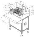
Fig. 1 is the utility model overall schematic;
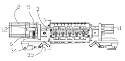
Fig. 2 is the utility model sectional perspective schematic diagram;
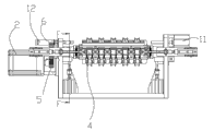
Fig. 3 is the utility model fragmentary top diagrammatic sketch;
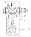
Fig. 4 is the local positive diagrammatic sketch of the utility model;
Fig. 5 is the F-F section diagrammatic sketch of Fig. 4;
Fig. 6 is the D-D section diagrammatic sketch of Fig. 3;
Fig. 7 is the overall schematic of the utility model drive unit;
Fig. 8 is the overall schematic of the utility model wire casing inversion mechanism;
Fig. 9 is the positive diagrammatic sketch of the utility model second transmission device;
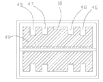
Figure 10 is the generalized section of the utility model workpiece.
Embodiment
Referring to figs. 1 through Figure 10, the utility model discloses a kind of double bull coil winding machine, comprise mainframe 1, mainframe 1 is provided with first power unit 2, be connected with first transmission device on first power unit 2, be connected with rollover stand 3 on first transmission device, and this rollover stand 3 by Bearing Installation on mainframe 1, rollover stand 3 one sides are provided with a plurality of first workpiece installation position (not shown)s, and opposite side is provided with the corresponding second workpiece installation position 4 in the position and the first workpiece installation position, described mainframe 1 is provided with driving and reversing mechanism, this driving and reversing mechanism is provided with and can drives the drive unit that workpiece rotates in the workpiece installation position, and described rollover stand 3 is provided with the automatic thread trimming device that can cut off line automatically.
As shown in the figure, in present embodiment, what first power unit 2 adopted is servomotor, because servomotor has the precision height, the advantage that controllability is good, be connected with first transmission device on the output of servomotor, first transmission device comprises the master gear 5 that is installed on first power unit, 2 outputs, be arranged at first driven gear 6 of input on the rollover stand 3, this master gear 5 is meshed with first driven gear 6, input is a power shaft that fixes with rollover stand 3, this power shaft by Bearing Installation on mainframe 1, rollover stand 3 one sides are provided with five first workpiece installation positions, and opposite side is provided with and five second workpiece installation positions 4 one to one, the first workpiece installation position.Certainly said structure is a kind of specific embodiment of this enforcement; do not constitute restriction of the present utility model; can also be 23 transmissions of two belt wheel winding belts as above-mentioned transmission device; or worm and gear transmission etc., but so long as to reach identical purpose with same or analogous structure all be to belong to protection range of the present utility model.And the quantity of the first workpiece installation position in this example also can be four or six etc.
As shown in the figure, in present embodiment, automatic thread trimming device comprises dead knife 7 that is arranged on the rollover stand 3 and the slip cutter 8 that matches with dead knife 7, and dead knife 7 is provided with first crossed beam trunking 9; Slip cutter 8 is provided with second crossed beam trunking 10 and the cut part, and mainframe 1 is provided with pushing mechanism 11 and resetting device 12, and pushing mechanism 11 can promote to slide cutter 8 slides and cuts off copper cash or enamelled wire with dead knife 7 effects; Resetting device 12 can make slip cutter 8 reset.Further, pushing mechanism 11 and resetting device 12 are for being arranged at the cylinder on the mainframe 1 respectively, and pushing mechanism 11 and resetting device 12 adopt cylinder, because cylinder is swift in response, and volume is little, compact conformation, and cost is low.Slip cutter 8 one ends are provided with screens step 13, cooperate this screens step 13, and the moving direction of slip cutter 8 is restricted, and can do rectilinear motion.
As shown in the figure, described driving and reversing mechanism comprises second cylinder 14 that is connected with mainframe 1, be fixed with advance and retreat bearing 15 on second cylinder 14, mainframe 1 is provided with slide-bar cover 16, advance and retreat bearing 15 is provided with advance and retreat slide-bar 99, advance and retreat slide-bar 99 is arranged in the slide-bar cover 16, and advance and retreat bearing 15 can overlap 16 along slide-bar and makes linear slide under the promotion of second cylinder 14.In present embodiment, drive unit is installed on the advance and retreat bearing 15, and what drive unit comprised 17 employings of second power unit, 17, the second power units is servomotor, because servomotor has the precision height, and the advantage that controllability is good.Be connected with second transmission device on second power unit 17, this second transmission device is provided with the driven wheel 19 that can be meshed with second driven gear 18 on the workpiece.Second transmission device comprises the driving pulley 20 that is arranged on second power unit 17, is arranged at rotation axis 21 on the driving and reversing mechanism by bearing, in present embodiment, rotation axis 21 comprises a mandrel and is set in five sections minor axises on this mandrel, connect into a major axis by connecting securing member, be provided with a driven wheel 19 on the every minor axis, this driven wheel 19 respectively be installed on the workpiece installation position in workpiece on second driven gear 18 corresponding, and can mesh.Said structure not only is convenient to processing, and easy accessibility, is convenient to safeguard.This rotation axis 21 is provided with driven pulley 22, and is arranged with belt 23 on this driving pulley 20 and the driven pulley 22, and described driven wheel 19 is arranged on the rotation axis 21.Adopting belt wheel and belt 23 transmissions is a kind of specific embodiment of this enforcement; do not constitute restriction of the present utility model; can also be two meshed transmission gear as above-mentioned transmission device; or worm and gear transmission etc., but so long as to reach identical purpose with same or analogous structure all be to belong to protection range of the present utility model.
As shown in the figure, described rollover stand 3 is provided with the clamping body that can tighten workpiece, this clamping body comprises the axis of guide 24 that is arranged in the rollover stand 3, these axis of guide 24 two ends are fixed with respectively opens piece 25, open piece 25 both sides and all be pivoted with first face 26 that bears down on one, the first roof pressure portion 27, first avoiding hollow groove 28, be respectively installed with compression spring 29 on the axis of guide 24, the compression spring 29 two ends respectively with open piece 25 and rollover stand 3 roof pressure mutually, rollover stand 3 both sides all are pivoted with clamp 30 and following clamp 31, last clamp 30 and down clamp 31 be provided with can with first face 26 second face 32 that bears down on one of roof pressure mutually that bears down on one, the first roof pressure portion 27 can reach a roof pressure of clamp 31 down with last clamp 30, the end of clamp 31 linked to each other with the two ends of reset tension spring 33 respectively under upward clamp 30 reached, be pivoted with the 5th cylinder 34 on the mainframe 1, be articulated with throw crank 35 on the 5th cylinder 34, and the approximate mid-section of this throw crank 35 and mainframe 1 articulate, and this throw crank 35 can open piece 25 by roof pressure under the promotion of the 5th cylinder 34.In present embodiment, be arranged with two the 5th cylinders 34 on the mainframe 1, said structure can be accomplished stress balance.
The course of work is as follows, when workpiece need be put into the workpiece installation position, press action button, the 5th cylinder 34 promotes throw crank 35 and rotates, throw crank 35 rotates around the pivoting point of itself and mainframe 1, one end roof pressure of throw crank 35 is opening on the piece 25, promotion is opened piece 25 and is moved, open piece 25 compression compression springs 29 and move, open first on the piece 25 bear down on one face 26 can roof pressure on clamp 30 and the face 32 that bears down on one of second on the clamp 31 down, last clamp 30 and clamp 31 pressurizeds and rotating around its pivoting point with rollover stand 3 down, an end of clamp 31 changed in first avoiding hollow groove 28 under last clamp 30 reached.At this moment, clamp 31 opened under last clamp 30 reached, and workpiece just can be put into workpiece installation slot.After workpiece is put into the workpiece installation position, press action button, the 5th cylinder 34 promotes throw crank 35 and rotates, throw crank 35 unclamps and opens piece 25, open piece 25 by compression spring 29 elastic force and retreat, simultaneously reset tension spring 33 also spur clamp 30 and down clamp 31 rotate around its pivoting point, an end of clamp 31 withdrawed from first avoiding hollow groove 28 under last clamp 30 reached, clamp 30 reaches the one side of clamp 31 down on the first roof pressure portion, the 27 difference roof pressures, and clamp 31 closes the fastening workpiece to make clamp 30 reach down.
As shown in the figure, also be provided with the wire casing inversion mechanism on the mainframe 1, this wire casing inversion mechanism comprises the line slideway auxiliary 36 on the advance and retreat bearing 15 that is arranged on the mainframe 1, line slideway auxiliary 36 is provided with the thread-changing plate, the thread-changing plate is provided with thread-changing groove 37, mainframe 1 is provided with thread-changing and promotes cylinder, and the thread-changing plate promotes cylinder with thread-changing and is connected.In present embodiment, the thread-changing plate comprises the first thread-changing plate 38 and the second thread-changing plate 39, and thread-changing promotes cylinder and comprises that the 3rd cylinder 40 and four-cylinder 41, the first thread-changing plates 38 are connected with the 3rd cylinder 40, and the second thread-changing plate 39 is connected with four-cylinder 41.By said mechanism, can uninterruptedly wind the line in the different wire casings in same workpiece.
The course of work is as follows, this workpiece has four wire casing positions, comprise first wire casing 45, second wire casing 46, the 3rd wire casing 47, the 4th wire casing 48, just need change to another wire casing after first wire casing 45 of workpiece and 46 coilings of second wire casing have been expired winds the line, at this moment, control system will transmit a signal to the 3rd cylinder 40 and four-cylinder 41, the 3rd cylinder 40 and four-cylinder 41 work, promote the first thread-changing plate 38 and the second thread-changing plate 39 along the certain distance of line slideway slip, thereby drive the line that is located in the thread-changing groove 37 and move to corresponding position, line will move into the 3rd wire casing 47 and the 4th wire casing 48 automatically.Certainly, have breach on the cell wall of first wire casing 45 and the 3rd wire casing 47, second wire casing 46 and the 4th wire casing 48, line just can change to another wire casing by this breach.
As shown in the figure, mainframe 1 is provided with locating mechanism, and this locating mechanism comprises the positioning cylinder 42 on being arranged on the mainframe 1, and positioning cylinder 42 is provided with backstay 43, rollover stand 3 is provided with location hole 44, and this backstay 43 can insert in this location hole 44.Said structure helps making rollover stand 3 maintenance levels, and more stable when work.
The course of work of the present utility model is as follows, on the first workpiece installation position that workpiece is installed on the rollover stand 3, gripping mechanism chucking workpiece hangs up properly line earlier, detent mechanism withdraws from, 2 work of first power unit, rollover stand 3 rotates 180 degree, and workpiece turns to the relevant position, at this moment, workpiece when the operator can wind the line at the workpiece on the first workpiece installation position, on second workpiece installation position installed simultaneously in the face of the operator in the second workpiece installation position.Driving and reversing mechanism is started working, second cylinder 14 promotes advance and retreat bearing 15 and moves, thereby driving driven wheel 19 moves into place, and second driven gear, 18 engagements on driven wheel 19 and the workpiece, second power unit, 17 work then drive driven wheel 19 by second transmission device and rotate, and driven wheel 19 drives second driven gear 18 and rotates, thereby the coil on the drive workpiece 49 rotates, and copper cash or enamelled wire rotate with coil 49 and in going into wire casing.In the coiling process, the line of a wire casing has been expired, can in another wire casing, continue coiling by the wire casing inversion mechanism, all wire casings are after finishing, rotation stops, and driving and reversing mechanism is started working, and second cylinder 14 promotes advance and retreat bearing 15 and returns, automatic thread trimming device is started working, and automatic thread trimming device is cut off the line that passes first crossed beam trunking 9 and second crossed beam trunking 10.At this moment, workpiece on the second workpiece installation position installs, detent mechanism withdraws from, 2 work of first power unit, rollover stand 3 rotates 180 degree, and the workpiece on the second workpiece installation position turns to the relevant position, and this moment, line will hang on the workpiece on the second workpiece installation position automatically, driving and reversing mechanism is started working, second cylinder 14 promotes advance and retreat bearing 15 and moves, and moves into place thereby drive driven wheel 19, begins coiling then, simultaneously, press operating key and open clamping body, at this moment, manually take off on the first workpiece installation position around the workpiece of expiring line, continue to pack into and treat around workpiece, thus the next circulation of beginning.
The utility model winds the line by bull, and hanging wire, trimming full-automation, so the utility model increased exponentially the operating efficiency of coiling, and alleviate working strength of workers.
Above-mentionedly just preferred embodiments more of the present utility model are illustrated and describe; but execution mode of the present utility model is not restricted to the described embodiments; as long as it reaches technique effect of the present utility model with essentially identical means, all should belong to protection range of the present utility model.
Claims (10)
1. double bull coil winding machine, it is characterized in that: comprise mainframe (1), mainframe (1) is provided with first power unit (2), first power unit is connected with first transmission device on (2), be connected with rollover stand (3) on first transmission device, and this rollover stand (3) by Bearing Installation on mainframe (1), rollover stand (3) one sides are provided with a plurality of first workpiece installation positions, and opposite side is provided with the corresponding second workpiece installation position (4) in the position and the first workpiece installation position, described mainframe (1) is provided with driving and reversing mechanism, this driving and reversing mechanism is provided with and can drives the drive unit that workpiece rotates in the workpiece installation position, and described rollover stand (3) is provided with the automatic thread trimming device that can cut off line automatically.
2. double bull coil winding machine according to claim 1, it is characterized in that: described first transmission device comprises the master gear (5) that is installed on first power unit (2) output, is arranged at first driven gear (6) on the rollover stand (3), and this master gear (5) is meshed with first driven gear (6).
3. double bull coil winding machine according to claim 1, it is characterized in that: described automatic thread trimming device comprises dead knife (7) that is arranged on the rollover stand (3) and the slip cutter (8) that matches with dead knife (7), and dead knife (7) is provided with first crossed beam trunking (9); Slip cutter (8) is provided with second crossed beam trunking (10) and cut part, mainframe (1) is provided with pushing mechanism (11) and resetting device (12), and pushing mechanism (11) can promote to slide the effect of cutter (8) and dead knife (7) and cut off copper cash or enamelled wire; Resetting device (12) can make slip cutter (8) reset.
4. double bull coil winding machine according to claim 3 is characterized in that: described pushing mechanism (11) and resetting device (12) are for being arranged at the cylinder on the mainframe (1) respectively, and described slip cutter (8) one ends are provided with screens step (13).
5. double bull coil winding machine according to claim 1, it is characterized in that: described driving and reversing mechanism comprises second cylinder (14) that is connected with mainframe (1), be fixed with advance and retreat bearing (15) on second cylinder (14), mainframe (1) is provided with slide-bar cover (16), advance and retreat bearings (15) are provided with advance and retreat slide-bar (99), advance and retreat slide-bars (99) are arranged in the slide-bar cover (16), and advance and retreat bearings (15) can be made linear slide along slide-bar cover (16) under the promotion of second cylinder (14).
6. double bull coil winding machine according to claim 1, it is characterized in that: described drive unit comprises second power unit (17), second power unit is connected with second transmission device on (17), and this second transmission device is provided with the driven wheel (19) that can be meshed with second driven gear (18) on the workpiece.
7. double bull coil winding machine according to claim 6, it is characterized in that: second transmission device comprises the driving pulley (20) that is arranged on second power unit (17), is arranged at rotation axis (21) on the driving and reversing mechanism by bearing, this rotation axis (21) is provided with driven pulley (22), and this driving pulley (20) passes through belt (23) transmission with driven pulley (22), and described driven wheel (19) is arranged on the rotation axis (21).
8. double bull coil winding machine according to claim 1, it is characterized in that: described rollover stand (3) is provided with the clamping body that can tighten workpiece, this clamping body comprises the axis of guide (24) that is arranged in the rollover stand (3), this axis of guide (24) two ends are fixed with respectively opens piece (25), open piece (25) both sides and be equipped with first face (26) that bears down on one, the first roof pressure portion (27), first avoiding hollow groove (28), be respectively installed with compression spring (29) on the axis of guide (24), the compression spring (29) two ends respectively with open piece (25) and rollover stand (3) roof pressure mutually, rollover stand (3) both sides all are pivoted with clamp (30) and following clamp (31), last clamp (30) and down clamp (31) be provided with can with first face (26) second face (32) that bears down on one of roof pressure mutually that bears down on one, the first roof pressure portion (27) can reach a roof pressure of clamp (31) down with last clamp (30), the end of clamp (31) linked to each other with the two ends of reset tension spring (33) respectively under upward clamp (30) reached, be pivoted with the 5th cylinder (34) on the mainframe (1), be articulated with throw crank (35) on the 5th cylinder (34), and approximate mid-section of this throw crank (35) and mainframe (1) articulate, and this throw crank (35) can open piece (25) by roof pressure under the promotion of the 5th cylinder (34).
9. double bull coil winding machine according to claim 1, it is characterized in that: described mainframe also is provided with the wire casing inversion mechanism on (1), this wire casing inversion mechanism comprises the line slideway auxiliary (36) that is arranged on the mainframe (1), line slideway auxiliary (36) is provided with the thread-changing plate, the thread-changing plate is provided with thread-changing groove (37), mainframe (1) is provided with thread-changing and promotes cylinder, and the thread-changing plate promotes cylinder with thread-changing and is connected.
10. double bull coil winding machine according to claim 1, it is characterized in that: described mainframe (1) is provided with locating mechanism, this locating mechanism comprises the positioning cylinder (42) that is arranged on the mainframe (1), positioning cylinder (42) is provided with backstay (43), rollover stand (3) is provided with location hole (44), and this backstay (43) can insert in this location hole (44).
Priority Applications (1)
| Application Number | Priority Date | Filing Date | Title |
|---|---|---|---|
| CN2011200183377U CN201994179U (en) | 2011-01-20 | 2011-01-20 | Duplex multi-head winding machine |
Applications Claiming Priority (1)
| Application Number | Priority Date | Filing Date | Title |
|---|---|---|---|
| CN2011200183377U CN201994179U (en) | 2011-01-20 | 2011-01-20 | Duplex multi-head winding machine |
Publications (1)
| Publication Number | Publication Date |
|---|---|
| CN201994179U true CN201994179U (en) | 2011-09-28 |
Family
ID=44670659
Family Applications (1)
| Application Number | Title | Priority Date | Filing Date |
|---|---|---|---|
| CN2011200183377U Expired - Fee Related CN201994179U (en) | 2011-01-20 | 2011-01-20 | Duplex multi-head winding machine |
Country Status (1)
| Country | Link |
|---|---|
| CN (1) | CN201994179U (en) |
Cited By (2)
| Publication number | Priority date | Publication date | Assignee | Title |
|---|---|---|---|---|
| CN102136366A (en) * | 2011-01-20 | 2011-07-27 | 珠海安电电子科技有限公司 | Dual station multi-head coiling machine |
| CN108861864A (en) * | 2018-07-23 | 2018-11-23 | 深圳市专诚达机电设备有限公司 | Mechanism to be expected |
-
2011
- 2011-01-20 CN CN2011200183377U patent/CN201994179U/en not_active Expired - Fee Related
Cited By (3)
| Publication number | Priority date | Publication date | Assignee | Title |
|---|---|---|---|---|
| CN102136366A (en) * | 2011-01-20 | 2011-07-27 | 珠海安电电子科技有限公司 | Dual station multi-head coiling machine |
| CN102136366B (en) * | 2011-01-20 | 2012-10-10 | 珠海恒阳科技有限公司 | Dual station multi-head coiling machine |
| CN108861864A (en) * | 2018-07-23 | 2018-11-23 | 深圳市专诚达机电设备有限公司 | Mechanism to be expected |
Similar Documents
| Publication | Publication Date | Title |
|---|---|---|
| CN102136366B (en) | Dual station multi-head coiling machine | |
| CN104319960A (en) | Wire winding machine for stator core of motor | |
| CN103346011B (en) | Fully automatic wire winding machine and preparation method thereof | |
| CN106160373B (en) | Four station single needle servo coil winding machines | |
| CN104752053A (en) | Double-group winding machine | |
| CN204179894U (en) | Motor stator core coil winding machine | |
| CN201994179U (en) | Duplex multi-head winding machine | |
| CN107659089A (en) | Around machine in a kind of nine axle brushless motor stators | |
| CN208146774U (en) | A kind of wrapping mold switching system | |
| CN104217853B (en) | A kind of automatic tape-wrapping winding robot | |
| CN103178664B (en) | Six-station multi-head winding machine | |
| CN115622348B (en) | Automatic winding machine for motor winding | |
| CN110817577A (en) | Intelligent cable conveying equipment | |
| CN203079438U (en) | Rotor protection layer automatic line-binding machine | |
| CN204067040U (en) | A kind of automatic tape-wrapping winding robot | |
| CN216543561U (en) | Cutting tool who has locate function is used in plastic film production | |
| CN202111597U (en) | Automatic winding device for T-shaped framework small motor rotor | |
| CN112110287B (en) | Automatic winding device for tin welding wires and winding method thereof | |
| CN109049025A (en) | A kind of polytetrafluoroethylcable cable twining package tape cutting processing burr finishing device | |
| CN102170203B (en) | Automatic T-shaped framework winding device for small motor rotor and alpha winding-end winding method | |
| CN103632839B (en) | Automatic winding assembly mechanism and method | |
| CN102992121B (en) | Automatic wire binding machine of protective layer of rotor | |
| CN204661003U (en) | A kind of admission machine | |
| CN210925756U (en) | Convenient wire unloading device of winding machine | |
| CN204470348U (en) | A kind of prestressed electric wire pole hangs gusset winding maker |
Legal Events
| Date | Code | Title | Description |
|---|---|---|---|
| C14 | Grant of patent or utility model | ||
| GR01 | Patent grant | ||
| C53 | Correction of patent for invention or patent application | ||
| CB03 | Change of inventor or designer information |
Inventor after: Zheng Mao Inventor after: Wu Yuanfu Inventor before: Wang Yadong Inventor before: Peng Keyi |
|
| COR | Change of bibliographic data |
Free format text: CORRECT: INVENTOR; FROM: WANG YADONG PENG KEYI TO: ZHENG MAO WU YUANFU |
|
| CF01 | Termination of patent right due to non-payment of annual fee | ||
| CF01 | Termination of patent right due to non-payment of annual fee |
Granted publication date: 20110928 Termination date: 20130120 |