CN201848787U - Rotating tool - Google Patents
Rotating tool Download PDFInfo
- Publication number
- CN201848787U CN201848787U CN2010202323175U CN201020232317U CN201848787U CN 201848787 U CN201848787 U CN 201848787U CN 2010202323175 U CN2010202323175 U CN 2010202323175U CN 201020232317 U CN201020232317 U CN 201020232317U CN 201848787 U CN201848787 U CN 201848787U
- Authority
- CN
- China
- Prior art keywords
- sleeve
- eccentric shaft
- workpiece
- clutch connector
- clutch
- Prior art date
- Legal status (The legal status is an assumption and is not a legal conclusion. Google has not performed a legal analysis and makes no representation as to the accuracy of the status listed.)
- Expired - Fee Related
Links
- 244000258271 Galium odoratum Species 0.000 claims abstract description 9
- 235000008526 Galium odoratum Nutrition 0.000 claims abstract description 9
- 238000000034 method Methods 0.000 abstract description 5
- 238000004519 manufacturing process Methods 0.000 abstract description 4
- 238000003754 machining Methods 0.000 abstract description 3
- 239000011324 bead Substances 0.000 abstract 1
- 238000005516 engineering process Methods 0.000 description 2
- 230000003993 interaction Effects 0.000 description 2
- 238000012986 modification Methods 0.000 description 2
- 230000004048 modification Effects 0.000 description 2
- 238000007514 turning Methods 0.000 description 2
- 230000009286 beneficial effect Effects 0.000 description 1
- 230000005540 biological transmission Effects 0.000 description 1
- 230000007812 deficiency Effects 0.000 description 1
- 230000000694 effects Effects 0.000 description 1
- 238000003780 insertion Methods 0.000 description 1
- 230000037431 insertion Effects 0.000 description 1
Images


Landscapes
- Jigs For Machine Tools (AREA)
Abstract
The utility model relates to a rotating tool suitable for a workpiece with four sides (360-degree rotation equally divided into 90 degrees) required to be processed. Aiming to the problem that in the process for processing the conventional workpiece, the workpiece is placed on a working table, then the workpiece is required to be aligned and clamped for times during the process of processing all the sides of the workpiece, and the requirements of production efficiency and machining accuracy can not be met, the novel rotating tool is designed to be characterized in that a main body, a disc, a flange, a spotting spindle, a handle, a clutch connector, an eccentric shaft, a sleeve (1), a gear, a spring (2), a rack and a positioning sleeve are included, wherein the main body and the disc are positioned through a tyre bead, the handle and the clutch connector are connected through a cylindrical pin, the clutch connector is connected with the eccentric shaft through a woodruff key, and the eccentric shaft is connected with the clutch connector through a jackscrew, so that the clutch connector and the eccentric shaft are positioned into a whole through the woodruff key and the jackscrew, and the clutch connector and the sleeve (1) are connected through the openings of the clutch connector and the sleeve (1). The rotating tool has simple structure, is convenient to use and can meet the requirements of production efficiency and machining accuracy.
Description
Technical field
The utility model is applicable to the workpiece that four sides that 360 ° of half-twists are divided equally need process
Background technology
Existing workpiece processing technology needs during each face of processing work workpiece is carried out repeatedly centering and clamping for workpiece is placed on the workbench, all can not satisfy existing production requirement on production efficiency still is machining accuracy.
The patent of invention content
The utility model has been studied a kind of rotary tooling being to overcome above-mentioned deficiency according to the processing request of workpiece.
The utility model is made up of body, disk, flange, apotting spindle, handle, clutch street corner, eccentric shaft, sleeve, gear, spring, tooth bar, positioning sleeve etc., it is characterized in that body and disk locate by the rim of the mouth, handle is connected by straight pin with clutch sub, clutch sub is connected by woodruff key with eccentric shaft, eccentric shaft is connected by jackscrew with clutch sub, and clutch sub and eccentric shaft are orientated one as by woodruff key and jackscrew like this.Clutch sub and sleeve 1 are connected by opening separately, and sleeve and gear produce interaction force, and return spring is pressed into the bottom of sleeve.
The beneficial effects of the utility model: utilize clamping of frock, can accurately locate each machined surface that 360 ° of half-twists of workpiece are divided equally, can process, this tool structure is simple, easy to operate.
Description of drawings
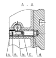
Fig. 1 is the transmission system front view, and Fig. 2 is the C-C cutaway view, and Fig. 3 is the A-A cutaway view.
1. body 2. disks 3. flanges 4. apotting spindles 5. handles 6. clutch subs 7. woodruff keies 8. eccentric shafts 9. jackscrews 10. sleeves 1 11. gears 12. return springs 1 13. sleeves 2 14. plug screws 15. springs 2 16. tooth bars 17. sleeves 3 18. positioning sleeves
The specific embodiment
As shown in the figure, Fig. 1. body 1 is located by the rim of the mouth with disk 2, and flange 3 is connected with fitting pin by tommyhead bolt with disk 2, and apotting spindle 4 is connected with flange by sunk screw, and apotting spindle 4, flange 3 and disk 2 connect as one like this.
Fig. 2 .C-C cutaway view, handle 5 and clutch sub 6 are connected by straight pin, clutch sub 6 is connected by woodruff key 7 with eccentric shaft 8, and eccentric shaft 8 is connected by jackscrew 9 with clutch sub 6, and clutch sub 6 is orientated one with eccentric shaft 8 as by woodruff key 7 and jackscrew 9 like this.Clutch sub 6 and sleeve 1 (10) are connected by opening separately, and sleeve 1 (10) produces interaction forces with gear 11, and return spring 1 (12) is pressed into the bottom of sleeve 13.
Fig. 3 .A-A cutaway view plug screw 14 is connected with spring 2 (15) and sleeve 3 (17), and tooth bar 16 is connected with spring 2 (15) and sleeve 3 (17), and tooth bar 16 is connected with positioning sleeve 18.
Operation principle:
Turning handle drives clutch sub, eccentric shaft, sleeve 1, this moment sleeve 1 driven gear, the rotation of gear driven tooth bar, gear blocks the retaining of gear by sleeve 2 and return spring 1, the spring 2 that is pressed into the tooth bar endoporus is pressed into by plug screw, the effect that 2 pairs of tooth bar starting powers of spring are shunk, rotational positioning axle in the time of turning handle, with the naked eye estimate about 90 ° of hour racks and stretch out in the body insertion positioning sleeve, but be just processing work of location this moment.After processing the workpiece one side, just can go back to handle, this hour rack retracts in the body, if just can be rotated further apotting spindle and handle when needing the processing another side, next 90 ° of location both can have been done, continue processing, the processing of back just can be operated until the processing of finishing workpiece equally according to the method for front.
The above only is preferred embodiment of the present utility model, is not structure of the present utility model is done any pro forma restriction.Every foundation technical spirit of the present utility model is to any simple modification, equivalent variations and modification that above embodiment did, all still belongs in the scope of technical scheme of patent of the present invention.
Claims (1)
1. rotary tooling, it is characterized in that it is made up of body, disk, flange, apotting spindle, handle, clutch street corner, eccentric shaft, sleeve 1, gear, spring 2, tooth bar, positioning sleeve, wherein body and disk are located by the rim of the mouth, handle is connected by straight pin with clutch sub, clutch sub is connected by woodruff key with eccentric shaft, eccentric shaft is connected by jackscrew with clutch sub, clutch sub and eccentric shaft are orientated one as by woodruff key and jackscrew, and clutch sub and sleeve 1 are connected by opening separately.
Priority Applications (1)
| Application Number | Priority Date | Filing Date | Title |
|---|---|---|---|
| CN2010202323175U CN201848787U (en) | 2010-06-22 | 2010-06-22 | Rotating tool |
Applications Claiming Priority (1)
| Application Number | Priority Date | Filing Date | Title |
|---|---|---|---|
| CN2010202323175U CN201848787U (en) | 2010-06-22 | 2010-06-22 | Rotating tool |
Publications (1)
| Publication Number | Publication Date |
|---|---|
| CN201848787U true CN201848787U (en) | 2011-06-01 |
Family
ID=44091198
Family Applications (1)
| Application Number | Title | Priority Date | Filing Date |
|---|---|---|---|
| CN2010202323175U Expired - Fee Related CN201848787U (en) | 2010-06-22 | 2010-06-22 | Rotating tool |
Country Status (1)
| Country | Link |
|---|---|
| CN (1) | CN201848787U (en) |
Cited By (2)
| Publication number | Priority date | Publication date | Assignee | Title |
|---|---|---|---|---|
| CN105934312A (en) * | 2014-03-10 | 2016-09-07 | 里奇工具公司 | tool holder |
| CN117207112A (en) * | 2023-11-09 | 2023-12-12 | 普达迪泰(成都)智造研究院有限公司 | Rotary mechanism capable of emergency resetting |
-
2010
- 2010-06-22 CN CN2010202323175U patent/CN201848787U/en not_active Expired - Fee Related
Cited By (3)
| Publication number | Priority date | Publication date | Assignee | Title |
|---|---|---|---|---|
| CN105934312A (en) * | 2014-03-10 | 2016-09-07 | 里奇工具公司 | tool holder |
| CN117207112A (en) * | 2023-11-09 | 2023-12-12 | 普达迪泰(成都)智造研究院有限公司 | Rotary mechanism capable of emergency resetting |
| CN117207112B (en) * | 2023-11-09 | 2024-02-23 | 普达迪泰(成都)智造研究院有限公司 | Rotary mechanism capable of emergency resetting |
Similar Documents
| Publication | Publication Date | Title |
|---|---|---|
| CN202752652U (en) | Drilling machine for multiple holes of flanges | |
| CN201848787U (en) | Rotating tool | |
| CN202572121U (en) | Chuck structure capable of automatically finishing groove parts of boxes | |
| CN202780547U (en) | Double-station machine tool rotary fixture | |
| CN103659570B (en) | A kind of grinding mechanism based on improving grinding efficiency | |
| CN203542068U (en) | Fourth-shaft revolving workbench used for numerically-controlled machine tool | |
| CN103934709A (en) | Fixture for rough boring of main cone bearing hole of main reducing gear of passenger car and machining of installation face of bearing pedestal | |
| CN203509213U (en) | Synchronous pulley burring device | |
| CN102962506B (en) | Detachable modularized milling accessory based on common lathe | |
| CN202174434U (en) | Polygonal clamping device | |
| CN201922282U (en) | Tool for milling spline tooth on end face of flange yoke | |
| CN209272912U (en) | Multi-spindle drilling tapper mechanism | |
| CN204381937U (en) | Transmission device for milling machine | |
| CN204546195U (en) | A kind of model aircraft screw thickness profile copy grinding device | |
| CN217413546U (en) | Automatic stopping system for part falling of polishing machine | |
| CN202292213U (en) | Fixture used for rotary lathe | |
| CN205927125U (en) | Diaxon numerical control duplex position chamfer special machine tool | |
| CN203636116U (en) | High-precision positioning clamp used for camshaft gear hobs | |
| CN204748019U (en) | A carousel machine for processing festival fork bearing hole | |
| CN219359087U (en) | Excavator part burnishing device | |
| CN203843783U (en) | Pretightening device | |
| CN201950525U (en) | Convenient and fast tooling mechanism for milling squares and key slots | |
| CN202239328U (en) | Wheel spoke punching center hole positioning device | |
| CN107774782A (en) | A kind of Novel transmission rotates mode structure | |
| CN203109315U (en) | Portable irregular workpiece machining device |
Legal Events
| Date | Code | Title | Description |
|---|---|---|---|
| C14 | Grant of patent or utility model | ||
| GR01 | Patent grant | ||
| DD01 | Delivery of document by public notice |
Addressee: Tianjin Construction Machinery Factory Document name: Notification of Termination of Patent Right |
|
| CF01 | Termination of patent right due to non-payment of annual fee |
Granted publication date: 20110601 Termination date: 20140622 |
|
| EXPY | Termination of patent right or utility model |