CN201848647U - High-power optical fiber conduction laser processing head - Google Patents
High-power optical fiber conduction laser processing head Download PDFInfo
- Publication number
- CN201848647U CN201848647U CN 201020604165 CN201020604165U CN201848647U CN 201848647 U CN201848647 U CN 201848647U CN 201020604165 CN201020604165 CN 201020604165 CN 201020604165 U CN201020604165 U CN 201020604165U CN 201848647 U CN201848647 U CN 201848647U
- Authority
- CN
- China
- Prior art keywords
- optical fiber
- cavity
- eyeglass
- power optical
- laser
- Prior art date
- Legal status (The legal status is an assumption and is not a legal conclusion. Google has not performed a legal analysis and makes no representation as to the accuracy of the status listed.)
- Expired - Lifetime
Links
- 239000013307 optical fiber Substances 0.000 title claims abstract description 25
- 238000012545 processing Methods 0.000 title abstract description 39
- 238000005259 measurement Methods 0.000 claims abstract description 29
- 239000011521 glass Substances 0.000 claims abstract description 10
- 230000001681 protective effect Effects 0.000 claims abstract description 10
- 230000007246 mechanism Effects 0.000 claims description 22
- 238000003754 machining Methods 0.000 claims description 16
- 239000000523 sample Substances 0.000 claims description 6
- 229910000906 Bronze Inorganic materials 0.000 claims description 5
- 239000010974 bronze Substances 0.000 claims description 5
- 238000001816 cooling Methods 0.000 claims description 5
- KUNSUQLRTQLHQQ-UHFFFAOYSA-N copper tin Chemical compound [Cu].[Sn] KUNSUQLRTQLHQQ-UHFFFAOYSA-N 0.000 claims description 5
- 230000010354 integration Effects 0.000 claims description 4
- XLYOFNOQVPJJNP-UHFFFAOYSA-N water Substances O XLYOFNOQVPJJNP-UHFFFAOYSA-N 0.000 claims description 4
- 238000006073 displacement reaction Methods 0.000 claims description 3
- 238000012544 monitoring process Methods 0.000 abstract description 9
- 238000005516 engineering process Methods 0.000 abstract description 5
- 238000010438 heat treatment Methods 0.000 abstract description 2
- 238000000605 extraction Methods 0.000 abstract 3
- 238000003466 welding Methods 0.000 abstract 1
- 238000000034 method Methods 0.000 description 15
- 239000013078 crystal Substances 0.000 description 4
- 239000000835 fiber Substances 0.000 description 4
- 230000005540 biological transmission Effects 0.000 description 3
- 230000005855 radiation Effects 0.000 description 3
- 230000033001 locomotion Effects 0.000 description 2
- 238000010791 quenching Methods 0.000 description 2
- 230000000171 quenching effect Effects 0.000 description 2
- 230000009286 beneficial effect Effects 0.000 description 1
- 238000005253 cladding Methods 0.000 description 1
- 239000000498 cooling water Substances 0.000 description 1
- 238000005520 cutting process Methods 0.000 description 1
- 239000003344 environmental pollutant Substances 0.000 description 1
- 238000012946 outsourcing Methods 0.000 description 1
- 231100000719 pollutant Toxicity 0.000 description 1
- 238000007669 thermal treatment Methods 0.000 description 1
Images


Landscapes
- Laser Beam Processing (AREA)
Abstract
The utility model relates to a high-power optical fiber conduction laser processing head, which belongs to the field of laser welding technology. The high-power optical fiber conduction laser processing head comprises a cavity, a first temperature sensor, a second temperature sensor, an optical fiber connecting port, a measuring device, a protecting air curtain, collimating lenses and a lens seat, wherein the two lenses are respectively mounted at two ends of the cavity through the lens seat; the optical fiber connecting port and a light extraction window are respectively formed on the cavity; the first temperature sensor is mounted at the end which is near to the collimating lenses on the cavity, and the probing end of the first temperature sensor extends into the cavity; the second sensor is mounted on the lens seat at the other end of the cavity, and the axial line of the probing end and the axial line of light paths of the two lenses form an included angle of 5 degrees to 10 degrees; a pair of protective glasses is arranged at the light extraction window; and the measuring device is mounted at the light extraction window. When in working, the protecting air curtain is mounted between the protective glasses and the measuring device. The high-power optical fiber conduction laser processing head can enable optical fiber conduction laser to perform precise measurement compensation on a continuous complex processing trajectory, perform real-time monitoring and recording on surface temperature of a workpiece, ensure the consistent quality of laser heat treatment and facilitate large-batch processing.
Description
Technical field
The utility model belongs to technical field of laser processing, particularly relates to a kind of large-power optical fiber conduction laser Machining head.
Background technology
The laser processing device of installing in robot or other five-axis linkage machine tools mechanisms at present can be realized the continuous processing of 3 D complex track substantially, but the running precision for the 3 D complex track is difficult to control in actual applications, repeatable accuracy on the workpiece between the track that track and movement executing mechanism moved of required processing place, in Laser Processing in the past, be difficult to guarantee, cause in laser processing procedure, laser emission is difficult to accurately control to position, angle, the focal length on the workpiece, and these factors are very big to the crudy influence.Stable processing quality is very important in Laser Processing in enormous quantities, and as far as possible simply, effectively monitoring or control the various factors that influences crudy is the effective ways that improve crudy.The laser Machining head that can be used for now on the fiber optic conduction laser instrument all is to adopt crystal eyeglass transmission focusing, can only be with cooling off indirectly, and the crystal eyeglass is difficult to bear high power laser, promptly enables to realize all improving a lot for environment for use and use cost.The crystal mirror is changed eyeglass and is difficult to, and can't realize that also a processing head realizes multiple laser processing technology.The monitoring of crudy all is based on crystal eyeglass transmission transmission in the laser processing procedure, is directed to the laser Machining head work in-process that adopts reflecting optics and monitors in real time and be unrealized.
The utility model content
At the technical problem of above-mentioned existence, the utility model provides a kind of large-power optical fiber conduction laser Machining head, and it is to use the laser of the laser instrument output of fiber optic conduction to carry out Laser Processing.
The technical solution adopted in the utility model is as follows:
The utility model comprises cavity; first; second temperature sensor; the optical fiber connector; measurement mechanism; the protection gas curtain; the collimation eyeglass; assemble eyeglass and microscope base; described two eyeglasses are installed in the cavity two ends by microscope base respectively; on cavity, be respectively equipped with optical fiber connector and light-emitting window; first temperature sensor is installed on the cavity near assembling the eyeglass end; its end of probe stretches in the cavity; second sensor is installed on the microscope base of the cavity other end; its end of probe axis becomes 5 ° of-10 ° of angles with two eyeglass light path axis; the place is provided with protective glass at light-emitting window; measurement mechanism is installed in the light-emitting window place; during work, the protection gas curtain is installed between protective glass and measurement mechanism.
The measuring junction of described measurement mechanism and laser coaxial and at the focus place of laser.Described measurement mechanism is the contact linear displacement transducer.
Described collimation eyeglass, gathering eyeglass are the bronze mirror sheet that has the spiral water-cooling structure of multichannel, are connected with water inlet pipe and outlet pipe by microscope base.Described gathering eyeglass is parabolic focus lamp, integration mirror or bifocus mirror.The measurement temperature range of described first sensor is 0-100 ℃; The measurement temperature range of second sensor is 0-1300 ℃.
The beneficial effects of the utility model:
Two eyeglasses that adopt in the utility model are the bronze mirror sheet that has spiral water-cooling structure, can bring up to 20kw to laser by power.Change different focusing lens and can make the hot spot of laser action on workpiece present different shapes, thereby realize different laser processing technologies.
Two sensors of the utility model are monitored in real time to the thermal radiation temperature on cavity internal and external environment temperature, protection eyeglass and the surface of the work respectively; can learn on the workpiece variation of temperature of processing place surface of the work in the laser processing procedure, thereby whether the monitoring crudy is stable.
The utility model can realize that fiber optic conduction laser carries out accurate metrophia compensation to the machining locus of continuous complexity; and in process, eyeglass is protected; temperature to surface of the work is carried out real-time monitoring record, can guarantee the Laser Heat Treating in China uniform quality, convenient processing in enormous quantities.
Description of drawings
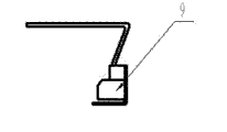
Fig. 1 does not install and measure the structural representation of device and protection gas curtain for the utility model.
Fig. 2 is the structural representation of protection gas curtain among Fig. 1.
Fig. 3 is a measurement mechanism structural representation among Fig. 1.
Fig. 4 is a structural representation behind Fig. 1 alignment measurement device.
Fig. 5 for Fig. 1 assemble the protection gas curtain after structural representation.
Among the figure: 1. optical fiber connector, 2. first sensor, 3. second sensor, 4. the collimation eyeglass is 5. assembled eyeglass, 6. cavity, 7. light-emitting window, 8. measurement mechanism, 9. protection gas curtain, 10. microscope base.
The specific embodiment
Below in conjunction with drawings and Examples the present invention is described in further detail.
Embodiment: as shown in Figure 1, the utility model comprises cavity 6, first, second temperature sensor 2,3, optical fiber connector 1, measurement mechanism 8, protection gas curtain 9, collimation eyeglass 4, assemble eyeglass 5 and microscope base 10, described two eyeglasses are installed in cavity 6 two ends by microscope base 10 respectively, on cavity 6, be respectively equipped with optical fiber connector 1 and light-emitting window 7, first temperature sensor 2 is installed on the cavity 6 near assembling eyeglass 5 ends, its end of probe stretches in the cavity 6, second sensor 3 is installed on the microscope base 10 of cavity 6 other ends, its end of probe axis becomes 5 ° of-10 ° of angles with two eyeglass light path axis, 7 places are provided with protective glass at light-emitting window, measurement mechanism 8 is installed in light-emitting window 7 places, its measuring junction and laser coaxial and at the focus place of laser; During work, protection gas curtain 9 is installed, as shown in Figure 2, is outsourcing piece at protective glass and 8 of measurement mechanisms; The measurement mechanism structure as shown in Figure 3, employing be the contact linear displacement transducer.
This routine described microscope base 10 is to be used for two eyeglasses are fixed on the cavity 6, has the hole of matching with two eyeglass water inlet pipe and water outlet pipes on the microscope base 10, through the switching of microscope base 10 eyeglass is introduced, drawn to cooling water.Described two eyeglasses are the bronze mirror sheet that has the spiral water-cooling structure of multichannel, are connected with inlet tube and outlet tube by microscope base 10.Can bring up to 20kw to laser by power, change different focusing lens 5 and can make the hot spot of laser action on workpiece present different shapes, thereby realize different laser processing technologies.This routine described gathering eyeglass 5 is parabolic focus lamp, integration mirror or bifocus mirror.
Adopt two pyrostats to carry out the real-time monitoring of cavity 6 internal and external environments and processing radiation in this example.It is 0-100 ℃ that described first sensor 2 is measured temperature range, and cavity 6 internal and external environment temperature are monitored in real time, reports to the police at once if temperature is too high, and the protection eyeglass temperature of light-emitting window 7 is monitored.The measurement temperature range of second sensor 3 is 0-1300 ℃, the heat radiation when being used for monitoring Laser Processing from the surface of the work.Can learn on the workpiece variation of temperature of processing place surface of the work in the laser processing procedure to processing thermal-radiating monitoring, if the temperature that is monitored is stable, that can prove that crudy is just stable; If the temperature instability that is monitored, that just proves that unusual fluctuations have taken place thermal treatment quality.Described optical fiber connector can dispose according to different needs, as: optical fiber connectors such as LLK – Auto, Trumpf LLK – B.Cavity 6 is used for fixing each device; Laser comes out to affact on the workpiece from light-emitting window 7, and Zhuan Pei protection eyeglass makes pollutant can not enter cavity 6 herein.The certainty of measurement of measurement mechanism 8 can reach 0.05mm.Protection gas curtain 9 is fixed on light-emitting window 7 places, in the LASER HEAT TREATMENT process protective glass of light-emitting window 7 is protected.By collimating eyeglass 4 and focusing lens 5, protection gas curtain 9, first, second temperature sensor 2,3 and trajectory measurement compensation arrangement; realize that fiber optic conduction laser carries out accurate metrophia compensation to the machining locus of continuous complexity; and in process, eyeglass is protected; temperature to surface of the work is carried out real-time monitoring record; can guarantee the Laser Heat Treating in China uniform quality, convenient processing in enormous quantities.
The course of work of the present utility model:
The utility model is fixed on robot or other five-axis linkage machine tools and uses.Obtain needed Laser Processing track by the software program on the motion, particularly need the three-dimensional track of processing continuously.After obtaining machining locus, load onto measurement mechanism 8 earlier at cavity light-emitting window of the present utility model place 7, known trajectory dry run one time, and in the dry run process, the utility model is measured and compensation to the distance of surface of the work is accurate, the angle that laser is incided workpiece is optimized, and judges the track presence of interference.The measuring junction of measurement mechanism 8 touches position on the workpiece and is laser spot and acts on position on the workpiece in this process, the influence of the crudy of the variation of laser focal is very big during Laser Processing, obtain stabilized quality, just need remain on the uniformity of laser focal in the process, the repeatable accuracy of the track by measuring back program track of gained and actual needs processing place on the workpiece gets and has also arrived raising.Before doing Laser Processing, measurement mechanism 8 is disassembled fit on protection gas curtain 9.In process, the protective glass of protection gas curtain 9 and light-emitting window 7 has been realized duplicate protection of the present utility model.Two pyrostats are monitored in real time to the quality conformance in the laser processing procedure, can get off by computer record.If any the big part of temperature fluctuation, after program executes, can recheck the part, the quality problems of some Laser Processing can be remedied.Thereby the quality of Laser Processing is monitored in real time, in process in enormous quantities, can guarantee the uniformity of quality.
The utility model in use can be changed different focus lenses, and bronze mirror sheets such as parabolic focus lamp, integration mirror, bifocus mirror are arranged, and can realize laser weld, cutting, cladding, quenching.
The utility model is primarily aimed at those local or whole workpiece that needs Laser Processing, presents three-dimensional machining locus on the workpiece again, such as the laser Machining head of laser die quenching and reparation, laser weld body in white or the like exploitation.The utility model improves the quality of Laser Processing with comparatively economical and practical method, has also improved efficient simultaneously.
Claims (6)
1. a large-power optical fiber conducts laser Machining head; it is characterized in that: comprise cavity; first; second temperature sensor; the optical fiber connector; measurement mechanism; the protection gas curtain; the collimation eyeglass; assemble eyeglass and microscope base; described two eyeglasses are installed in the cavity two ends by microscope base respectively; on cavity, be respectively equipped with optical fiber connector and light-emitting window; first temperature sensor is installed on the cavity near assembling the eyeglass end; its end of probe stretches in the cavity; second sensor is installed on the microscope base of the cavity other end; its end of probe axis becomes 5 ° of-10 ° of angles with two eyeglass light path axis; the place is provided with protective glass at light-emitting window; measurement mechanism is installed in the light-emitting window place; during work, the protection gas curtain is installed between protective glass and measurement mechanism.
2. large-power optical fiber according to claim 1 conduction laser Machining head is characterized in that: the measuring junction of described measurement mechanism and laser coaxial and at the focus place of laser.
3. large-power optical fiber conduction laser Machining head according to claim 1 and 2, it is characterized in that: described measurement mechanism is the contact linear displacement transducer.
4. large-power optical fiber conduction laser Machining head according to claim 1 is characterized in that: described collimation eyeglass, gathering eyeglass are the bronze mirror sheet that has the spiral water-cooling structure of multichannel, are connected with water inlet pipe and outlet pipe by microscope base.
5. according to claim 1 or 4 described large-power optical fiber conduction laser Machining heads, it is characterized in that: described gathering eyeglass is parabolic focus lamp, integration mirror or bifocus mirror.
6. large-power optical fiber conduction laser Machining head according to claim 1, it is characterized in that: the measurement temperature range of described first sensor is 0-100 ℃; The measurement temperature range of second sensor is 0-1300 ℃.
Priority Applications (1)
| Application Number | Priority Date | Filing Date | Title |
|---|---|---|---|
| CN 201020604165 CN201848647U (en) | 2010-11-12 | 2010-11-12 | High-power optical fiber conduction laser processing head |
Applications Claiming Priority (1)
| Application Number | Priority Date | Filing Date | Title |
|---|---|---|---|
| CN 201020604165 CN201848647U (en) | 2010-11-12 | 2010-11-12 | High-power optical fiber conduction laser processing head |
Publications (1)
| Publication Number | Publication Date |
|---|---|
| CN201848647U true CN201848647U (en) | 2011-06-01 |
Family
ID=44091060
Family Applications (1)
| Application Number | Title | Priority Date | Filing Date |
|---|---|---|---|
| CN 201020604165 Expired - Lifetime CN201848647U (en) | 2010-11-12 | 2010-11-12 | High-power optical fiber conduction laser processing head |
Country Status (1)
| Country | Link |
|---|---|
| CN (1) | CN201848647U (en) |
Cited By (5)
| Publication number | Priority date | Publication date | Assignee | Title |
|---|---|---|---|---|
| CN106312570A (en) * | 2016-09-27 | 2017-01-11 | 大连大学 | Multifunctional machining machine tool |
| CN109317821A (en) * | 2017-07-24 | 2019-02-12 | 北京中科镭特电子有限公司 | A kind of laser welding system |
| CN109967891A (en) * | 2017-12-28 | 2019-07-05 | 刘海平 | A kind of high-precision automobile parts cutting device |
| CN109990910A (en) * | 2017-12-29 | 2019-07-09 | 大族激光科技产业集团股份有限公司 | A kind of laser head eyeglass system for detecting temperature and method |
| CN114226968A (en) * | 2021-11-23 | 2022-03-25 | 深圳市汉威激光设备有限公司 | Drive and motor integrated hand-held swing welding head |
-
2010
- 2010-11-12 CN CN 201020604165 patent/CN201848647U/en not_active Expired - Lifetime
Cited By (5)
| Publication number | Priority date | Publication date | Assignee | Title |
|---|---|---|---|---|
| CN106312570A (en) * | 2016-09-27 | 2017-01-11 | 大连大学 | Multifunctional machining machine tool |
| CN109317821A (en) * | 2017-07-24 | 2019-02-12 | 北京中科镭特电子有限公司 | A kind of laser welding system |
| CN109967891A (en) * | 2017-12-28 | 2019-07-05 | 刘海平 | A kind of high-precision automobile parts cutting device |
| CN109990910A (en) * | 2017-12-29 | 2019-07-09 | 大族激光科技产业集团股份有限公司 | A kind of laser head eyeglass system for detecting temperature and method |
| CN114226968A (en) * | 2021-11-23 | 2022-03-25 | 深圳市汉威激光设备有限公司 | Drive and motor integrated hand-held swing welding head |
Similar Documents
| Publication | Publication Date | Title |
|---|---|---|
| CN201848647U (en) | High-power optical fiber conduction laser processing head | |
| US11085829B2 (en) | Infrared temperature-measurement probe | |
| CN204913068U (en) | Be applicable to totally enclosed laser three -dimensional cutting head of manipulator cage constrction | |
| CN205816815U (en) | A kind of truning fixture of LASER HEATING auxiliary | |
| CN203418230U (en) | Laser cutting and welding integrated anti-collision water-cooling focus head | |
| CN105223661A (en) | A kind of optical fiber precision focusing coupling device and Method of Adjustment | |
| CN105127589B (en) | Similar SCARA robot capable of allowing laser beams to pass through | |
| CN107505065A (en) | High-order mode F P interfere the preparation method and device of pyrometric probe sensor | |
| CN105067546A (en) | High-temperature multispectral coupling optical-mechanical system | |
| CN107576265A (en) | The measuring method that a kind of laser interferometer focuses automatically | |
| CN116330089B (en) | In-situ measurement time-controlled grinding device and measurement method thereof | |
| CN110887449B (en) | A thread measuring device | |
| CN119805662B (en) | Laser welding-based integrated high-temperature optical fiber sensor coupling packaging device and method | |
| CN211539913U (en) | A laser coupling adjustment mechanism with water cooling | |
| CN106271051A (en) | A kind of three-dimension flexible low power laser system of processing | |
| CN203696235U (en) | Galvanometer structure of laser welding machine | |
| CN206047769U (en) | Optical fiber sensing measuring system | |
| CN204934856U (en) | High-precision laser welding camera lens can be monitored | |
| CN206140208U (en) | Optical localization aims at appearance | |
| CN111203632A (en) | Method for monitoring laser focus in real time | |
| Schmidt et al. | Realization and first time operation of a high-power laser-water-jet system | |
| CN201720605U (en) | Three-dimensional flexible processing system based on industry joint light guiding arm | |
| CN113686241A (en) | High-temperature surface line laser geometric measurement error analysis method | |
| CN206139982U (en) | Three -dimensional flexible low power laser system of processing | |
| CN212552349U (en) | Device for monitoring laser focus in real time |
Legal Events
| Date | Code | Title | Description |
|---|---|---|---|
| C14 | Grant of patent or utility model | ||
| GR01 | Patent grant | ||
| CX01 | Expiry of patent term | ||
| CX01 | Expiry of patent term |
Granted publication date: 20110601 |