CN201848463U - Bending machine employing double-machine linkage - Google Patents
Bending machine employing double-machine linkage Download PDFInfo
- Publication number
- CN201848463U CN201848463U CN2010206133979U CN201020613397U CN201848463U CN 201848463 U CN201848463 U CN 201848463U CN 2010206133979 U CN2010206133979 U CN 2010206133979U CN 201020613397 U CN201020613397 U CN 201020613397U CN 201848463 U CN201848463 U CN 201848463U
- Authority
- CN
- China
- Prior art keywords
- oil cylinder
- programmable logic
- bender
- logic controller
- plc
- Prior art date
- Legal status (The legal status is an assumption and is not a legal conclusion. Google has not performed a legal analysis and makes no representation as to the accuracy of the status listed.)
- Expired - Fee Related
Links
- 238000005452 bending Methods 0.000 title abstract description 16
- 239000003921 oil Substances 0.000 claims description 74
- 238000003462 Bender reaction Methods 0.000 claims description 20
- 239000000446 fuel Substances 0.000 claims description 6
- 239000010729 system oil Substances 0.000 claims description 3
- 102100026205 1-phosphatidylinositol 4,5-bisphosphate phosphodiesterase gamma-1 Human genes 0.000 claims 5
- 101100190617 Arabidopsis thaliana PLC2 gene Proteins 0.000 claims 5
- 101100408456 Arabidopsis thaliana PLC8 gene Proteins 0.000 claims 5
- 101100464304 Caenorhabditis elegans plk-3 gene Proteins 0.000 claims 5
- 101000691599 Homo sapiens 1-phosphatidylinositol 4,5-bisphosphate phosphodiesterase gamma-1 Proteins 0.000 claims 5
- 101100093534 Saccharomyces cerevisiae (strain ATCC 204508 / S288c) RPS1B gene Proteins 0.000 claims 5
- 230000001360 synchronised effect Effects 0.000 abstract description 20
- 238000000034 method Methods 0.000 abstract description 8
- 238000005259 measurement Methods 0.000 abstract description 3
- 230000003247 decreasing effect Effects 0.000 abstract 1
- 239000002828 fuel tank Substances 0.000 description 4
- 230000003993 interaction Effects 0.000 description 4
- 238000010586 diagram Methods 0.000 description 3
- 238000006073 displacement reaction Methods 0.000 description 3
- 230000007812 deficiency Effects 0.000 description 2
- 238000001514 detection method Methods 0.000 description 2
- 238000005516 engineering process Methods 0.000 description 2
- 230000007704 transition Effects 0.000 description 2
- 229910000831 Steel Inorganic materials 0.000 description 1
- 230000005540 biological transmission Effects 0.000 description 1
- 239000010727 cylinder oil Substances 0.000 description 1
- 230000000694 effects Effects 0.000 description 1
- 238000009434 installation Methods 0.000 description 1
- 230000016507 interphase Effects 0.000 description 1
- 238000003754 machining Methods 0.000 description 1
- 238000010008 shearing Methods 0.000 description 1
- 239000010959 steel Substances 0.000 description 1
- 230000003245 working effect Effects 0.000 description 1
Images


Landscapes
- Fluid-Pressure Circuits (AREA)
Abstract
The utility model relates to a bending machine employing double-machine linkage, comprising two bending machines of the same type, wherein the two bending machines are respectively configured with a programmable logic controller. The two bending machines of the same type are closely arranged in one straight line, the tool rests of the two bending machines are positioned in the same plane, and the lower molds of the two bending machines are also positioned in the same straight line. Pistons of two oil cylinders of each bending machine are mechanically synchronized through a synchronous shaft, and adopt the method of serial oil supply. An oil conveying pipeline of each oil cylinder is respectively provided with more than three pressure relays, and the pressure relays are respectively connected with the signal input end of the programmable logic controller. The two groups of corresponding pressure relays have the same set pressure value. After the two bending machines obtain the same starting signal, the oil cylinders drive the tool rests to move downward simultaneously. The bending machine employing double-machine linkage belongs to the direct measurement of contact force, so the precision is high and the reliability is good; the cost of the pressure relay is low, the number of pressure relays can be conveniently increased or decreased, the set pressure is simple to adjust, and the double-machine linkage operation requirement is satisfied for different grades of bending machines.
Description
Technical field
The utility model relates to the machining equipment field, especially the technical scheme of bender field dual-machine linkage.
Background technology
At present, the common size of the turning machine worktable that sell in market is at 4000 (mm), and full-size generally is no more than 6000 (mm).Add man-hour when super long workpiece occurring, wish to adopt the moving co-operation of two All-China Federation of Taiwan Compatriots, promptly two bender bed dies are arranged point-blank, and the slide block DL synchronization of two benders drives the cutter bending workpieces, satisfies super long workpiece bending requirement.Current, two synchronous main technical schemes of bender have synchronous, electric synchronous, the synchronous three kinds of modes of numerical control of mechanical type.Wherein, mechanical type is to utilize mechanical transmissioning piece that the slide block of two benders is rigidly connected synchronously, realizes that by force two bender slide blocks are synchronous.Mechanical type is realized synchronously simple, reliable operation, but limited two bender independently workings, and promptly when super long workpiece occurring processing not, two benders are thrown off cumbersome.The synchronous technical scheme of numerical control is an installation site detecting sensor on the slide block of two benders, adopts proportional valve control to enter the flow of oil cylinder, realizes two bender slide block DL synchronizations.Though numerical control can be satisfied the requirement that two benders can link and can work alone synchronously, but digital control system and proportioning valve cost are all than higher, only on high-grade bender, just dispose digital control system and proportioning valve, limited the application of this technology in common bender.Electric synchronous employing travel switch by electric control method, is realized two bender slide block down controls as position detecting device.Because plate is generally the steel workpiece, the value of elastic modulus E is very big, in the bending process, even it is very little to contact the displacement increment between cutter and workpiece, also will produce very big contact force increment.Select for use travel switch to detect the displacement of bender slide block, control two benders and keep obviously existing synchronously great technological deficiency, therefore electric method for synchronous is difficult to put into practice on engineering.
The bender two-shipper is synchronous, require the cutter of two benders that workpiece is applied bending power synchronously in essence, guarantee that phenomenons such as warpage, skew do not appear in workpiece in the bending process, satisfy the flexure plane shape unanimity that workpiece forms on two benders, curved groove is in alignment., numerical control synchronous three kind deficiencies that mode exist synchronous, electric synchronously at mechanical type, the utility model is controlled based on power, realizes bender two-shipper synchronizing function.
The domestic patent that relates to the bender of dual-machine linkage has 3.Wherein " the electric synchronous control system of multiple linkage bender (CN2205264Y) " and " transmission bender, plate shearing machine, paper cutter, forcing press and their merging machine (CN1049467) on the hydraulic pressure " all adopts travel switch to detect the slide unit position, the two platform bender slide block synchronization actions of control; " the synchronous detection control apparatus of CN201149655Y numerical control bender two-shipper " adopts the sync position detection sensor to detect the slide unit displacement, utilizes electromagnetic proportional valve control oil cylinder oil inlet quantity, realizes two device synchronization operations.Therefore, above-mentioned three patents all do not relate to the utility model based on force information, realize the technical scheme of two-shipper synchronous interaction.
Summary of the invention
In order to solve the two-shipper synchronous interaction problem of two benders more easily, the utility model provides a kind of bender of realizing the two-shipper synchronous interaction based on force information.
Concrete technical solution is as follows:
The bender of dual-machine linkage comprises two the bender A2 and the bender B6 of same model, and dispose programmable logic controller (PLC) APLC1 and programmable logic controller (PLC) BPLC2 respectively, two bender A2 of described same model and bender B6 are close to layout point-blank, its knife rest A1 and knife rest B8 are in same plan-position, and the bed die of two benders also is in same linear position; The oil cylinder A3 of described bender A2 and the piston of oil cylinder B4 are by the synchronizing shaft mechanical synchronization, and the oil cylinder C5 of described bender B6 and the piston of oil cylinder D7 are by the synchronizing shaft mechanical synchronization; Described oil cylinder A3 and oil cylinder B4 adopt the mode of serial fuel feeding, described oil cylinder C5 and oil cylinder D7 adopt the mode of serial fuel feeding, on the pipeline road 11 of oil cylinder A3 and oil cylinder B4, arrange the pressure switch more than three respectively, and connecting the signal input part of programmable logic controller (PLC) APLC1 respectively; Equally, the difference correspondence is arranged the pressure switch more than three on the pipeline road 24 of oil cylinder C5 and oil cylinder D7, and is connecting the signal input part of programmable logic controller (PLC) BPLC2 respectively, and the force value that the pressure switch of above-mentioned two groups of correspondences is set equates; Two benders are after obtaining common enabling signal, and oil cylinder A3 and oil cylinder B4 drive knife rest A1, and it is simultaneously descending that oil cylinder C5 and oil cylinder D7 drive knife rest B8; Subsequently, after two groups of pressure switches such as detected successively at duty pressure, it is descending that knife rest A1 and knife rest B8 can continue, to guarantee that contact force keeps synchronously between cutter A14 and cutter B27 and workpiece.
On the pipeline road 11 of described oil cylinder A3 and oil cylinder B4, arrange five pressure switches respectively, on the pipeline road 24 of described oil cylinder C5 and oil cylinder D7, arrange five pressure switches respectively; Five pressure switches on the pipeline road 11 are connected on five signal input parts of programmable logic controller (PLC) APLC1 respectively; Five pressure switches on the pipeline road 24 are connected on five signal input parts of programmable logic controller (PLC) BPLC2 respectively; One of them signal input part of programmable logic controller (PLC) APLC1 is connecting start button A41, one of them signal input part of programmable logic controller (PLC) BPLC2 is connecting start button B42, and start button A41 and start button B42 adopt mechanical ganged switch, realize starting synchronously; Programmable logic controller (PLC) APLC1 output signal control two-position two-way solenoid valve 10, programmable logic controller (PLC) BPLC2 output signal control two-position two-way solenoid valve 23 is realized the control to the hydraulic system oil circuit.
Useful technique effect of the present utility model is: the cutter and the contact force between workpiece of two benders are divided into five grades from small to large, the cutter of two benders and the contact force between workpiece synchronously, satisfy the synchronous requirement of omnidistance contact force thereby be similar on five grades.The characteristics of the implementation method of bender dual-machine linkage are: detect indirect measurement scheme with the slide position and compare, force information has reflected the essence of cutter and workpiece interphase interaction, belongs to direct measurement; Therefore, precision height, good reliability.The pressure switch cost is low, and quantity increase and decrease pressure adjustment convenient, that set is simple, can satisfy multiple class bender dual-machine linkage job requirements.
Description of drawings
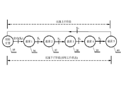
Fig. 1 is that the utility model two-shipper is arranged schematic diagram.
Fig. 2 is the Synchronization Control hydraulic schematic diagram.
Fig. 3 is the synchronization control circuit schematic diagram.
Fig. 4 is knife rest running status figure.
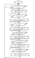
Fig. 5 is the dual-machine linkage control flow chart.
The specific embodiment
Below in conjunction with accompanying drawing, the utility model is further described by embodiment.
Embodiment 1:
Referring to Fig. 1 and Fig. 2, the bender of dual-machine linkage comprises two benders of same model, i.e. bender A2 and bender B6, and two benders dispose programmable logic controller (PLC) APLC1 and programmable logic controller (PLC) BPLC2 respectively.
Two bender A2 of same model and bender B6 are close to layout point-blank, and its knife rest A1 and knife rest B8 are in same plan-position, and the bed die of two benders also is in same linear position.The oil cylinder A3 of bender A2 and the piston of oil cylinder B4 are by the synchronizing shaft mechanical synchronization, and the oil cylinder C5 of bender B6 and the piston of oil cylinder D7 are by the synchronizing shaft mechanical synchronization; Oil cylinder A3 and oil cylinder B4 adopt the mode of serial fuel feeding, and oil cylinder C5 and oil cylinder D7 adopt the mode of serial fuel feeding.
Power source A9 is added to the oil cylinder A3 epicoele of bender A2 by two-position two-way solenoid valve 10, pipeline 11.The epicoele of the cavity of resorption of oil cylinder A3 and oil cylinder B4 20 is communicated with by the road, and the cavity of resorption of oil cylinder B4 is communicated with fuel tank by pipeline 21.After pipeline 11 was connected power source A9, the piston of oil cylinder A3 and oil cylinder B4 was simultaneously descending, and was connected with hinge B19 by hinge A16, and the knife rest A1 that drives bender A2 is descending.
Power source B22 is added to the epicoele of bender B6 oil cylinder C5 by two-position two-way solenoid valve 23, pipeline 24.The epicoele of the cavity of resorption of oil cylinder C5 and oil cylinder D7 32 is communicated with by the road, and the cavity of resorption of oil cylinder D7 is communicated with fuel tank by pipeline 34.After pipeline 24 was connected power source 22, the piston of oil cylinder C5 and oil cylinder D7 was simultaneously descending, and was connected with 33 by hinge 29, and the knife rest B8 that drives bender B6 is descending.
Referring to Fig. 3, for contact force between the cutter B27 of the cutter A14 that realizes bender A2 and bender B6 and workpiece keeps synchronously, on the pipeline road 11 of oil cylinder A3 and oil cylinder B4, arrange five pressure switches respectively, be pressure switch A12, pressure switch B13, pressure switch C15, pressure switch D17, pressure switch E18, and connecting five signal input part IN2, IN3, IN4, IN5, the IN6 of programmable logic controller (PLC) APLC1 respectively; Equally, five pressure switches of corresponding respectively layout on the pipeline road 24 of oil cylinder C5 and oil cylinder D7, be pressure switch F25, pressure switch G26, pressure switch H28, pressure switch I30, pressure switch J31, and connecting signal input part IN2, IN3, IN4, IN5, the IN6 of programmable logic controller (PLC) BPLC2 respectively; The force value that the pressure switch of above-mentioned two groups of correspondences is set equates.One of them signal input part of programmable logic controller (PLC) APLC1 is connecting start button A41, one of them signal input part of programmable logic controller (PLC) BPLC2 is connecting start button B42, and start button A41 and start button B42 adopt mechanical ganged switch, realize starting synchronously; The coil K1 of programmable logic controller (PLC) APLC1 output signal control two-position two-way solenoid valve 10, the coil K2 of programmable logic controller (PLC) BPLC2 output signal control two-position two-way solenoid valve 23 realizes the control to the hydraulic system oil circuit.
The pressure that pressure switch A12, pressure switch B13, pressure switch C15, pressure switch D17, pressure switch E18 set is designated as P successively
11, P
12, P
13, P
14And P
15The pressure that pressure switch F25, pressure switch G26, pressure switch H28, pressure switch I30, pressure switch J31 set is designated as P successively
21, P
22, P
23, P
24And P
25, and satisfy condition:
P
11=P
21,P
12=P
22,P
13=P
23,P
14=P
24,P
15=P
25;
P
11=P
21<P
12=P
22<P
13=P
23<P
14=P
24<P
15=P
25
Reach the setting pressure P of pressure switch A12, pressure switch B13, pressure switch C15, pressure switch D17, pressure switch E18 respectively when the pressure of pipeline 11
11, P
12, P
13, P
14And P
15The time, the respective signal note of its output is made S
11, S
12, S
13, S
14And S
15, become logical one by logical zero respectively; In like manner, reach the setting pressure P of pressure switch F25, pressure switch G26, pressure switch H28, pressure switch I30, pressure switch J31 respectively when the pressure of pipeline 24
21, P
22, P
23, P
24And P
25The time, the respective signal S of its output
21, S
22, S
23, S
24And S
25Also become logical one by logical zero respectively.
Referring to Fig. 2 and Fig. 4, the contact force between the cutter A14 of two benders, cutter B27 and workpiece, it is synchronous to be divided into Pyatyi from small to large.Pyatyi is remembered the state 36,37,38,39 and 40 of doing synchronously respectively, and descent of piston initial position note is made state 35.Shifting triggering signal between each state remembers respectively and makes S
0, S
1, S
2, S
3, S
4And S
5
Referring to Fig. 2, Fig. 4 and Fig. 5, knife rest A1 and knife rest B8 are descending and that return fast, and the course of work is as follows:
The first step: before knife rest A1 and knife rest B8 were descending, the initialize signal of each pressure switch output was:
S
11=S
12=S
13=S
14=S
15=0
S
21=S
22=S
23=S
24=S
25=0
After operating personnel press start button 41 and 42, S
0=1, knife rest A1 and knife rest B8 begin descending.
Second step: when cutter A14 with after workpiece contacts, the pressure of pipeline 11 rises to P
11, the output signal S of pressure switch 12
11=1 o'clock, knife rest A1 went downwards to state 36; When cutter B27 with after workpiece contacts, the pressure of pipeline 24 rises to P
21, the output signal S of pressure switch F25
21=1 o'clock, knife rest B8 also ran to state 36.Has only the S of satisfying
1=S
11S
21=1 condition, promptly contact force all reaches load 1 between cutter A14 and cutter B27 and workpiece, and knife rest A1 and knife rest B8 can continue descending from state 36 automatically, and after this contact force will further increase between cutter A14 and cutter B27 and workpiece, trend state 37.
The 3rd step: after knife rest A1 and knife rest B8 arrive state 37, satisfy S
2=S
12S
22=1 condition, knife rest A1 and knife rest B8 continue descending automatically, to state 38 transition.
The 4th step: after knife rest A1 and knife rest B8 arrive state 38, satisfy S
3=S
13S
23=1 condition, knife rest A1 and knife rest B8 continue descending automatically, shift to state 39.
The 5th step: after knife rest A1 and knife rest B8 arrive state 39, satisfy S
4=S
14S
24=1 condition, knife rest A1 and knife rest B8 continue descending automatically, to state 40 transition.
The 6th step: after knife rest A1 and knife rest B8 arrive state 40, satisfy S
5=S
15S
25=1 condition, knife rest A1 and knife rest B8 stop descending, and behind the time-delay certain hour (about 1s-2s), return (up) fast, return state 35.
So far, the time processing process is finished, and waits for that operating personnel press start button A41 and start button B42 once more, enters next working cycles.
When unit works alone, only need pressure switch A12, pressure switch B13, pressure switch C15, pressure switch D17, pressure switch E18 and pressure switch F25, pressure switch G26, pressure switch H28, pressure switch I30, pressure switch J31 are switched to mechanical switch, and all be arranged to closure state, the mechanical duplex function of start button A41 and start button B42 disconnects, then association of the signal of two benders and synchronizing function are cancelled, can work alone respectively, function is independent of each other.
Embodiment 2:
According to the synchronization accuracy requirement, can be on in-line 11 and pipeline 24, each arranges three or four pressure switches, other is with embodiment 1.
Embodiment 3:
According to the synchronization accuracy requirement, can be on in-line 11 and pipeline 24, each arranges six or seven or eight pressure switches, other is with embodiment 1.
Embodiment 4:
In pressure switch being arranged in pipeline 20 and pipeline 32, other is with embodiment 1.
Embodiment 5: in-line 11 is connected to oil cylinder B4 epicoele, and pipeline 20 is connected between oil cylinder B4 cavity of resorption and the oil cylinder A3 epicoele, and oil cylinder A3 cavity of resorption is received fuel tank by pipeline 21; In-line 24 is connected to oil cylinder D7 epicoele, and pipeline 32 is connected between oil cylinder D7 cavity of resorption and the oil cylinder C5 epicoele, and oil cylinder C5 cavity of resorption takes back fuel tank by pipeline 34, and other is with embodiment 1.
Claims (2)
1. the bender of dual-machine linkage, two the bender A (2) and the bender B (6) that comprise same model, and dispose programmable logic controller (PLC) A(PLC1 respectively) and programmable logic controller (PLC) B(PLC2), it is characterized in that: two bender A of described same model (2) and bender B (6) are close to layout point-blank, its knife rest A (1) and knife rest B (8) are in same plan-position, and the bed die of two benders also is in same linear position; The oil cylinder A (3) of described bender A (2) and the piston of oil cylinder B (4) are by the synchronizing shaft mechanical synchronization, and the oil cylinder C (5) of described bender B (6) and the piston of oil cylinder D (7) are by the synchronizing shaft mechanical synchronization; Described oil cylinder A (3) and oil cylinder B (4) adopt the mode of serial fuel feeding, described oil cylinder C (5) and oil cylinder D (7) adopt the mode of serial fuel feeding, on the pipeline road (11) of oil cylinder A (3) and oil cylinder B (4), arrange the pressure switch more than three respectively, and connecting programmable logic controller (PLC) A(PLC1 respectively) signal input part; Equally, go up the corresponding respectively pressure switch of arranging more than three at the pipeline road (24) of oil cylinder C (5) and oil cylinder D (7), and connecting programmable logic controller (PLC) B(PLC2 respectively) signal input part, the force value that the pressure switch of above-mentioned two groups of correspondences is set equates; Two benders are after obtaining common enabling signal, and oil cylinder A (3) and oil cylinder B (4) drive knife rest A (1), and it is simultaneously descending that oil cylinder C (5) and oil cylinder D (7) drive knife rest B (8); Subsequently, after two groups of pressure switches such as detected successively at duty pressure, it is descending that knife rest A (1) and knife rest B (8) can continue, to guarantee that contact force keeps synchronously between cutter A (14) and cutter B (27) and workpiece.
2. the bender of dual-machine linkage according to claim 1, it is characterized in that: on the pipeline road (11) of described oil cylinder A (3) and oil cylinder B (4), arrange five pressure switches respectively, on the pipeline road (24) of described oil cylinder C (5) and oil cylinder D (7), arrange five pressure switches respectively; Five pressure switches on the pipeline road (11) are connected on programmable logic controller (PLC) A(PLC1 respectively) five signal input parts; Five pressure switches on the pipeline road (24) are connected on programmable logic controller (PLC) B(PLC2 respectively) five signal input parts; Programmable logic controller (PLC) A(PLC1) one of them signal input part is connecting start button A (41), programmable logic controller (PLC) B(PLC2) one of them signal input part is connecting start button B (42), and start button A (41) and start button B (42) adopt mechanical ganged switch, realize starting synchronously; Programmable logic controller (PLC) A(PLC1) output signal control two-position two-way solenoid valve (10), programmable logic controller (PLC) B(PLC2) output signal control two-position two-way solenoid valve (23), realize control to the hydraulic system oil circuit.
Priority Applications (1)
| Application Number | Priority Date | Filing Date | Title |
|---|---|---|---|
| CN2010206133979U CN201848463U (en) | 2010-11-19 | 2010-11-19 | Bending machine employing double-machine linkage |
Applications Claiming Priority (1)
| Application Number | Priority Date | Filing Date | Title |
|---|---|---|---|
| CN2010206133979U CN201848463U (en) | 2010-11-19 | 2010-11-19 | Bending machine employing double-machine linkage |
Publications (1)
| Publication Number | Publication Date |
|---|---|
| CN201848463U true CN201848463U (en) | 2011-06-01 |
Family
ID=44090877
Family Applications (1)
| Application Number | Title | Priority Date | Filing Date |
|---|---|---|---|
| CN2010206133979U Expired - Fee Related CN201848463U (en) | 2010-11-19 | 2010-11-19 | Bending machine employing double-machine linkage |
Country Status (1)
| Country | Link |
|---|---|
| CN (1) | CN201848463U (en) |
Cited By (11)
| Publication number | Priority date | Publication date | Assignee | Title |
|---|---|---|---|---|
| CN102837423A (en) * | 2011-11-23 | 2012-12-26 | 南通力德尔机电科技有限公司 | Full-automatic flexible plate bending machine |
| CN104942087A (en) * | 2015-06-29 | 2015-09-30 | 绍兴市安雅信自动化技术有限公司 | Electro-hydraulic synchronous bending machine and control method thereof |
| CN105033001A (en) * | 2015-07-14 | 2015-11-11 | 绍兴市安雅信自动化技术有限公司 | Double-machine linkage torsion shaft bending machine |
| CN105618521A (en) * | 2014-11-03 | 2016-06-01 | 黄石华信机械设备有限公司 | Three electrical linkage twist shaft synchronous bending machines |
| CN106862326A (en) * | 2017-04-26 | 2017-06-20 | 江苏江海机床集团有限公司 | The large-sized sheet material Double-linkage bender of quickly replacing mould |
| CN106862317A (en) * | 2017-04-26 | 2017-06-20 | 江苏江海机床集团有限公司 | The horizontal Double-linkage bender of view-based access control model identification |
| CN106862322A (en) * | 2017-04-26 | 2017-06-20 | 江苏江海机床集团有限公司 | The large-sized sheet material Double-linkage bender of continuous bending |
| CN106862325A (en) * | 2017-04-24 | 2017-06-20 | 江苏江海机床集团有限公司 | Large-sized sheet material Double-linkage bender |
| CN106964712A (en) * | 2017-04-26 | 2017-07-21 | 江苏江海机床集团有限公司 | Horizontal Double-linkage bender hanging feed arrangement |
| CN107052098A (en) * | 2017-04-24 | 2017-08-18 | 江苏江海机床集团有限公司 | A kind of horizontal Double-linkage bender |
| CN116237398A (en) * | 2023-05-06 | 2023-06-09 | 江苏特威机床制造有限公司 | Double-linkage synchronous bending machine |
-
2010
- 2010-11-19 CN CN2010206133979U patent/CN201848463U/en not_active Expired - Fee Related
Cited By (15)
| Publication number | Priority date | Publication date | Assignee | Title |
|---|---|---|---|---|
| CN102837423A (en) * | 2011-11-23 | 2012-12-26 | 南通力德尔机电科技有限公司 | Full-automatic flexible plate bending machine |
| CN105618521A (en) * | 2014-11-03 | 2016-06-01 | 黄石华信机械设备有限公司 | Three electrical linkage twist shaft synchronous bending machines |
| CN104942087A (en) * | 2015-06-29 | 2015-09-30 | 绍兴市安雅信自动化技术有限公司 | Electro-hydraulic synchronous bending machine and control method thereof |
| CN104942087B (en) * | 2015-06-29 | 2017-05-17 | 绍兴市安雅信自动化技术有限公司 | Electro-hydraulic synchronous bending machine and control method thereof |
| CN105033001A (en) * | 2015-07-14 | 2015-11-11 | 绍兴市安雅信自动化技术有限公司 | Double-machine linkage torsion shaft bending machine |
| CN106862325A (en) * | 2017-04-24 | 2017-06-20 | 江苏江海机床集团有限公司 | Large-sized sheet material Double-linkage bender |
| CN107052098B (en) * | 2017-04-24 | 2019-05-24 | 江苏江海机床集团有限公司 | A horizontal double linkage bending machine |
| CN107052098A (en) * | 2017-04-24 | 2017-08-18 | 江苏江海机床集团有限公司 | A kind of horizontal Double-linkage bender |
| CN106862317A (en) * | 2017-04-26 | 2017-06-20 | 江苏江海机床集团有限公司 | The horizontal Double-linkage bender of view-based access control model identification |
| CN106964712A (en) * | 2017-04-26 | 2017-07-21 | 江苏江海机床集团有限公司 | Horizontal Double-linkage bender hanging feed arrangement |
| CN106862322A (en) * | 2017-04-26 | 2017-06-20 | 江苏江海机床集团有限公司 | The large-sized sheet material Double-linkage bender of continuous bending |
| CN106862317B (en) * | 2017-04-26 | 2018-11-06 | 江苏江海机床集团有限公司 | The horizontal Double-linkage bender of view-based access control model identification |
| CN106862326A (en) * | 2017-04-26 | 2017-06-20 | 江苏江海机床集团有限公司 | The large-sized sheet material Double-linkage bender of quickly replacing mould |
| CN116237398A (en) * | 2023-05-06 | 2023-06-09 | 江苏特威机床制造有限公司 | Double-linkage synchronous bending machine |
| CN116237398B (en) * | 2023-05-06 | 2023-07-11 | 江苏特威机床制造有限公司 | Double-linkage synchronous bending machine |
Similar Documents
| Publication | Publication Date | Title |
|---|---|---|
| CN201848463U (en) | Bending machine employing double-machine linkage | |
| CN102866665B (en) | Multi-axial synchronous control system and method for all-electric bending machine | |
| CN102183918B (en) | Control system for servo numerical control bending machine | |
| CN202106443U (en) | Full-automatic hydraulic pressure machine | |
| CN206317443U (en) | Servo hydraulic press position control system with high accuracy | |
| CN202803847U (en) | Multi-shaft synchronous control system for all-electric bending machine | |
| CN202639056U (en) | Intelligent guide rail forming machine | |
| CN116068953A (en) | Control system and method for double-push hand computerized panel saw with shiftable clamps | |
| CN104772407A (en) | Control system based on numerical-control wire bending robot | |
| CN101284286A (en) | Benders for offset load processing | |
| CN201047912Y (en) | Numerically-controlled machine tool range control device | |
| CN201941099U (en) | Electric control system of constant-pressure type hydraulic spacing regulating device | |
| CN106286485B (en) | Linear motion article is accurately positioned and resetting method and apparatus | |
| CN202438593U (en) | Hydraulic control system for controlling punch press punching process | |
| CN102453487B (en) | Gas exchange controlling device | |
| CN201186312Y (en) | Hydraulic synchronous device of rolling machine work roll | |
| CN102699156B (en) | Electro-hydraulic control multi-cylinder linkage bending machine | |
| CN201776341U (en) | Movable die holder-type U-shaped beam flange plate punching machine | |
| CN201130311Y (en) | Computer control apparatus of high speed independent quilter | |
| CN202539289U (en) | Long standalone four-cylinder hydraulic plate bender | |
| CN201291261Y (en) | Multi-group pre-cutting stamping machine tool | |
| CN220148322U (en) | Belt conveyor adjusting device | |
| CN103019149A (en) | Control system for brick making machine set and control method thereof | |
| CN109624386B (en) | 500-ton four-column hydraulic press servo control system | |
| CN202052826U (en) | Pressure feedback control system for bending machine |
Legal Events
| Date | Code | Title | Description |
|---|---|---|---|
| C14 | Grant of patent or utility model | ||
| GR01 | Patent grant | ||
| CF01 | Termination of patent right due to non-payment of annual fee |
Granted publication date: 20110601 Termination date: 20151119 |
|
| EXPY | Termination of patent right or utility model |