CN201781801U - Vehicle for pruning roadside ornamental shrubs - Google Patents
Vehicle for pruning roadside ornamental shrubs Download PDFInfo
- Publication number
- CN201781801U CN201781801U CN2010202885990U CN201020288599U CN201781801U CN 201781801 U CN201781801 U CN 201781801U CN 2010202885990 U CN2010202885990 U CN 2010202885990U CN 201020288599 U CN201020288599 U CN 201020288599U CN 201781801 U CN201781801 U CN 201781801U
- Authority
- CN
- China
- Prior art keywords
- fixed
- cut
- cutting
- movable scissors
- plane
- Prior art date
- Legal status (The legal status is an assumption and is not a legal conclusion. Google has not performed a legal analysis and makes no representation as to the accuracy of the status listed.)
- Expired - Fee Related
Links
Images


Landscapes
- Scissors And Nippers (AREA)
Abstract
The utility model discloses a vehicle for pruning roadside ornamental shrubs, which comprises a motor vehicle assembly, wherein a rail is fixed on the chassis of a motor vehicle in front of a driver building, a rail-guided vehicle capable of being mechanically positioned is arranged on the rail, a retractable lifter is fixed on the undercarriage of the rail-guided vehicle, two or three sawtooth-type fixed scissors and two or three sawtooth-type movable scissors are fixed at the top of the retractable rod of the retractable lifter to form an inverted-L shaped or inverted-U shaped mechanical scissors, a guide sleeve is fixed on the casing wall of the retractable lifter, a guide rod is fixed at the top of the retractable rod of the retractable lifter, and the guide rod is in sliding fit with the guide sleeve. The vehicle for pruning roadside ornamental shrubs can simultaneously prune the top surface and the two side surfaces of the ornamental shrub zones on the two sides of the road and suck and collect the broken shrub branches falling on the road, and has high work efficiency.
Description
Technical field
The utility model relates to a kind of pruning equipment, especially a kind of pruning vehicle for roadside ornamental shrubs.
Background technology
Application number is 03218000.4, and Granted publication number discloses a kind of nursery stock Pruning machine for the Chinese utility model patent of CN2619475Y; Application number is 200710113428.7, and publication number is that the Chinese utility application prospectus of CN101406143 discloses a kind of vehicle for pruning plant on urban road; These two kinds of nursery stock clipping devices all have only the plane to prune, there is not side trim, can not once finish trimming and finishing work to urban road both sides ornamental shrub band, the pruning of ornamental shrub band both sides, urban road both sides, also need the workman to finish by hand, simultaneously, the broken branch of shrub that is scattered on the road is also needed manually to clean inefficiency.Therefore, designing a kind of end face and the side that can be with urban road both sides ornamental shrub simultaneously and prune the pruning vehicle for roadside ornamental shrubs that also the broken branch of shrub that is scattered on the road can be siphoned away simultaneously, be the present technical issues that need to address.
Summary of the invention
Technical problem to be solved in the utility model provides a kind of end face and the side that can be with urban road both sides ornamental shrub simultaneously prune the pruning vehicle for roadside ornamental shrubs that also the broken branch of shrub that is scattered on the road can be siphoned away simultaneously.
The technical scheme in the invention for solving the technical problem is:
A kind of pruning vehicle for roadside ornamental shrubs, form by the motor vehicle assembly, on the motor-vehicle chassis of front portion, driver building, be fixed with track, track be provided with can machinery location the track car, on the hull of track car, be fixed with telescopic lifting dress, top at the expansion link of telescopic lifting dress is fixed with " ┍ " type or " Π " type mechanical scissor that is made of two or three serration type fixed blades and two or three serration type movable scissors, on the shell wall of telescopic lifting dress, be fixed with fairlead, top at the expansion link of telescopic lifting dress is fixed with guide post, and guide post and fairlead are slidingly matched.
The technical scheme in the invention for solving the technical problem can also be:
Track described in the utility model is " worker " word steel, be provided with and the parallel leading screw of " worker " word steel by lead screw shaft bearing and gearbox at " worker " word steel rear portion, the road wheel of track car is embedded in the groove of " worker " word steel both sides, on the road wheel axle bracket, be fixed with screw, the screw spinning is on leading screw, leading screw is connected with the output shaft of gearbox, and the power of the power shaft of gearbox can be independent motor or provide power by motor vehicle.
Two the serration type fixed blades of " ┍ " described in the utility model type mechanical scissor and the cutting edge of two serration type movable scissors are all towards the place ahead, one of them serration type fixed blade is that fixed blade is cut on the plane, another serration type fixed blade is for vertically cutting fixed blade, the serration type movable scissors of cutting the fixed blade pairing with the plane is that movable scissors is cut on the plane, be the vertical movable scissors of cutting with the vertical serration type movable scissors of cutting the fixed blade pairing, the plane is cut movable scissors and is provided power with the vertical movable scissors of cutting by the same output shaft of boring the tooth gearbox, on the output shaft of awl tooth gearbox, first crank is installed, the end of cutting movable scissors on the plane is hinged with the plane and cuts connecting rod, it is all hinged with first crank that the other end of connecting rod is cut on the plane, it is the hinged cover of diplopore that the hinged hinged cover of connecting rod and first crank is cut on the plane, in the another one hinge hole of the hinged cover of diplopore, be hinged with and vertically cut connecting rod by jointed shaft, the other end of vertically cutting connecting rod is with vertical to cut movable scissors hinged, the plane is cut movable scissors and promptly is equivalent to " slide block " that the slider-crank mechanism that connecting rod and first crank constituted is cut on the plane, vertically cuts movable scissors and promptly is equivalent to vertically to cut " slide block " that connecting rod is vertically cut connecting rod and the slider-crank mechanism that is constituted with first crank.
The utility model is at described ┍ " plane of the type mechanical scissor other end of cutting fixed blade is fixed with cutting edge and also vertically cuts fixed blade towards second of the place ahead; and the vertical movable scissors of cutting the fixed blade pairing with second is the second vertical movable scissors of cutting; second vertically cuts movable scissors provides power by the another one output shaft of awl tooth gearbox; the end at the another one output shaft of awl tooth gearbox is provided with second crank; be hinged with second in second end of vertically cutting movable scissors and vertically cut connecting rod; second vertically to cut the other end and second crank of connecting rod hinged, and vertical formation " Π " the type mechanical scissor of cutting with two is cut on described plane.
Telescopic lifting dress described in the utility model is cylinder, and the source of the gas of cylinder is the gas storage bag of vehicle-mounted air pump, and the power of vehicle-mounted air pump is provided by motor car engine.
The utility model also is equipped with fan blower on described automobile assembly chassis, on the air outlet of fan blower, injecting tube is installed, the discharge duct that leads to the compartment is installed on the jet orifice of injecting tube, on the air entry of injecting tube, be connected with the broken branch of shrub suction pipe, the broken branch of shrub suction pipe and motor-vehicle chassis are fixed on the road face that its mouth of pipe stretches to the curb place, and the broken branch of shrub that is scattered in the road limit can be by shrub broken suction pipe, injecting tube and discharge duct inspiration compartment.
Compared with prior art, the utility model can be pruned simultaneously also and the broken branch of shrub that is scattered on the road can be siphoned away the end face and the side of urban road both sides ornamental shrub band simultaneously, and the ornamental shrub band is pruned one-shot forming, high efficiency.
Description of drawings
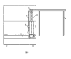
Fig. 1 is the front view of structural representation of the present utility model.
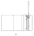
Fig. 2 is the right view (" ┍ " type embodiment) of Fig. 1.
Fig. 3 is the right view (" Π " type embodiment) of Fig. 1.
Fig. 4 is the vertical view (" ┍ " type embodiment) of Fig. 1.
Fig. 5 is the vertical view (" Π " type embodiment) of Fig. 1.
Fig. 6 is the utility model electric clippers fundamental diagram (" ┍ " type embodiment).
A is to view (part) among Fig. 7 Fig. 6.
Fig. 8 is the utility model electric clippers transmission system schematic diagram.
Fig. 9 is that the broken branch of the utility model shrub is penetrated suction cleaning schematic diagram.
Embodiment
As shown in the figure, a kind of pruning vehicle for roadside ornamental shrubs, form by the motor vehicle assembly, on the motor-vehicle chassis of front portion, driver building, be fixed with track 1, track 1 be provided with can machinery location track car 2, on the hull of track car 2, be fixed with telescopic lifting and adorn 3, the top of adorning 3 expansion link in telescopic lifting is fixed with " ┍ " type or " Π " type mechanical scissor 4 that is made of two or three serration type fixed blades and two or three serration type movable scissors, adorn in telescopic lifting on 3 the shell wall and be fixed with fairlead 5, the top of adorning 3 expansion link in telescopic lifting is fixed with guide post 6, and guide post 6 is slidingly matched with fairlead 5.Described track 1 is " worker " word steel, be provided with and the parallel leading screw 10 of " worker " word steel by lead screw shaft bearing 8 and gearbox 11 at " worker " word steel rear portion, the road wheel of track car 2 is embedded in the groove of " worker " word steel both sides, on the road wheel axle bracket, be fixed with screw 9, screw 9 spinnings are on leading screw 10, leading screw 10 is connected with the output shaft of gearbox 11, and the power of the power shaft of gearbox 11 can be independent motor or provide power by motor vehicle.Two the serration type fixed blades of described " ┍ " type mechanical scissor 4 and the cutting edge of two serration type movable scissors are all towards the place ahead, one of them serration type fixed blade is that fixed blade is cut on the plane, another serration type fixed blade is for vertically cutting fixed blade, the serration type movable scissors of cutting the fixed blade pairing with the plane is that movable scissors is cut on the plane, be the vertical movable scissors of cutting with the vertical serration type movable scissors of cutting the fixed blade pairing, the plane is cut movable scissors and is provided power with the vertical movable scissors of cutting by the same output shaft of boring tooth gearbox 7, on the output shaft of awl tooth gearbox 7, first crank 12 is installed, the end of cutting movable scissors on the plane is hinged with the plane and cuts connecting rod 13, it is all hinged with first crank 12 that the other end of connecting rod 13 is cut on the plane, it is the hinged cover of diplopore that the hinged hinged cover of connecting rod 13 and first crank 12 is cut on the plane, in the another one hinge hole of the hinged cover of diplopore, be hinged with and vertically cut connecting rod 18 by jointed shaft, the other end of vertically cutting connecting rod 18 is with vertical to cut movable scissors hinged, the plane is cut movable scissors and promptly is equivalent to " slide block " that the slider-crank mechanism that connecting rod 13 and first crank 12 constituted is cut on the plane, vertically cuts movable scissors and promptly is equivalent to vertically to cut " slide block " that connecting rod 18 is vertically cut connecting rod 18 and the slider-crank mechanism that is constituted with first crank 12.At described ┍ " plane of type mechanical scissor 4 other end of cutting fixed blade is fixed with cutting edge and also vertically cuts fixed blade towards second of the place ahead; and the vertical movable scissors of cutting the fixed blade pairing with second is the second vertical movable scissors of cutting; second vertically cuts movable scissors provides power by the another one output shaft of awl tooth gearbox 7; end at the another one output shaft of awl tooth gearbox 7 is provided with second crank 19; be hinged with second in second end of vertically cutting movable scissors and vertically cut connecting rod; second vertically to cut the other end and second crank 19 of connecting rod hinged, and vertical formation " Π " the type mechanical scissor of cutting with two is cut on described plane.Described telescopic lifting is adorned 3 and is cylinder, and the source of the gas of cylinder is the gas storage bag of vehicle-mounted air pump, and the power of vehicle-mounted air pump is provided by motor car engine.On described automobile assembly chassis, fan blower 14 is installed also, injecting tube 15 is installed on the air outlet of fan blower 14, the discharge duct 17 that leads to compartment 18 is installed on the jet orifice of injecting tube 15, be connected with the broken branch of shrub suction pipe 16 on the air entry of injecting tube 15, the broken branch of shrub suction pipe 16 and motor-vehicle chassis are fixed on the road face that its mouth of pipe stretches to the curb place.
Claims (6)
1. pruning vehicle for roadside ornamental shrubs, form by the motor vehicle assembly, it is characterized in that: on the motor-vehicle chassis of front portion, driver building, be fixed with track (1), track (1) be provided with can machinery location track car (2), on the hull of track car (2), be fixed with telescopic lifting dress (3), the top of adorning the expansion link of (3) in telescopic lifting is fixed with " ┍ " type or " Π " type mechanical scissor (4) that is made of two or three serration type fixed blades and two or three serration type movable scissors, on the shell wall of telescopic lifting dress (3), be fixed with fairlead (5), the top of adorning the expansion link of (3) in telescopic lifting is fixed with guide post (6), and guide post (6) is slidingly matched with fairlead (5).
2. a kind of pruning vehicle for roadside ornamental shrubs according to claim 1, it is characterized in that: described track (1) is " worker " word steel, be provided with the leading screw (10) parallel at " worker " word steel rear portion by lead screw shaft bearing (8) and gearbox (11) with " worker " word steel, the road wheel of track car (2) is embedded in the groove of " worker " word steel both sides, on the road wheel axle bracket, be fixed with screw (9), screw (9) spinning is on leading screw (10), leading screw (10) is connected with the output shaft of gearbox (11), and the power of the power shaft of gearbox (11) can be independent motor or provide power by motor vehicle.
3. a kind of pruning vehicle for roadside ornamental shrubs according to claim 2, it is characterized in that: two the serration type fixed blades of described " ┍ " type mechanical scissor (4) and the cutting edge of two serration type movable scissors are all towards the place ahead, one of them serration type fixed blade is that fixed blade is cut on the plane, another serration type fixed blade is for vertically cutting fixed blade, the serration type movable scissors of cutting the fixed blade pairing with the plane is that movable scissors is cut on the plane, be the vertical movable scissors of cutting with the vertical serration type movable scissors of cutting the fixed blade pairing, the plane is cut movable scissors and is provided power with the vertical movable scissors of cutting by the same output shaft of boring tooth gearbox (7), on the output shaft of awl tooth gearbox (7), first crank (12) is installed, the end of cutting movable scissors on the plane is hinged with the plane and cuts connecting rod (13), it is all hinged with first crank (12) that the other end of connecting rod (13) is cut on the plane, it is the hinged cover of diplopore that the hinged hinged cover of connecting rod (13) and first crank (12) is cut on the plane, in the another one hinge hole of the hinged cover of diplopore, be hinged with and vertically cut connecting rod (18) by jointed shaft, the other end of vertically cutting connecting rod (18) is with vertical to cut movable scissors hinged, the plane is cut movable scissors and promptly is equivalent to " slide block " that the slider-crank mechanism that connecting rod (13) and first crank (12) constituted is cut on the plane, vertically cuts movable scissors and promptly is equivalent to vertically to cut " slide block " that connecting rod (18) is vertically cut connecting rod (18) and the slider-crank mechanism that is constituted with first crank (12).
4. a kind of pruning vehicle for roadside ornamental shrubs according to claim 3, it is characterized in that: the other end of cutting fixed blade on the plane of described " ┍ " type mechanical scissor (4) is fixed with cutting edge and also vertically cuts fixed blade towards second of the place ahead, the vertical movable scissors of cutting the fixed blade pairing with second is the second vertical movable scissors of cutting, second vertically cuts movable scissors provides power by the another one output shaft of boring tooth gearbox (7), end at the another one output shaft of boring tooth gearbox (7) is provided with second crank (19), be hinged with second in second end of vertically cutting movable scissors and vertically cut connecting rod, second vertically to cut the other end and second crank (19) of connecting rod hinged, and vertical formation " Π " the type mechanical scissor of cutting with two is cut on described plane.
5. a kind of pruning vehicle for roadside ornamental shrubs according to claim 1 is characterized in that: described telescopic lifting dress (3) is a cylinder, and the source of the gas of cylinder is the gas storage bag of vehicle-mounted air pump, and the power of vehicle-mounted air pump is provided by motor car engine.
6. a kind of pruning vehicle for roadside ornamental shrubs according to claim 1, it is characterized in that: on described automobile assembly chassis, fan blower (14) is installed also, injecting tube (15) is installed on the air outlet of fan blower (14), the discharge duct (17) that leads to compartment (18) is installed on the jet orifice of injecting tube (15), be connected with the broken branch of shrub suction pipe (16) on the air entry of injecting tube (15), shrub broken branch suction pipe (16) and motor-vehicle chassis are fixed on the road face that its mouth of pipe stretches to the curb place.
Priority Applications (1)
| Application Number | Priority Date | Filing Date | Title |
|---|---|---|---|
| CN2010202885990U CN201781801U (en) | 2010-08-11 | 2010-08-11 | Vehicle for pruning roadside ornamental shrubs |
Applications Claiming Priority (1)
| Application Number | Priority Date | Filing Date | Title |
|---|---|---|---|
| CN2010202885990U CN201781801U (en) | 2010-08-11 | 2010-08-11 | Vehicle for pruning roadside ornamental shrubs |
Publications (1)
| Publication Number | Publication Date |
|---|---|
| CN201781801U true CN201781801U (en) | 2011-04-06 |
Family
ID=43813793
Family Applications (1)
| Application Number | Title | Priority Date | Filing Date |
|---|---|---|---|
| CN2010202885990U Expired - Fee Related CN201781801U (en) | 2010-08-11 | 2010-08-11 | Vehicle for pruning roadside ornamental shrubs |
Country Status (1)
| Country | Link |
|---|---|
| CN (1) | CN201781801U (en) |
Cited By (5)
| Publication number | Priority date | Publication date | Assignee | Title |
|---|---|---|---|---|
| CN103155811A (en) * | 2013-02-03 | 2013-06-19 | 李健 | Green belt pruning machine |
| CN104641964A (en) * | 2015-03-11 | 2015-05-27 | 包宇青 | Road greening equipment with side face cutting function and application method thereof |
| CN104686211A (en) * | 2015-03-11 | 2015-06-10 | 汪涛 | Road greening equipment using motor driving device and application method of road greening equipment |
| CN105594467A (en) * | 2016-03-03 | 2016-05-25 | 四川省农业机械研究设计院 | Vertical three-dimensional pruning machine for tea gardens |
| CN106034773A (en) * | 2016-08-04 | 2016-10-26 | 安徽鑫苗园林景观建设有限公司 | Garden-shrub clipping device |
-
2010
- 2010-08-11 CN CN2010202885990U patent/CN201781801U/en not_active Expired - Fee Related
Cited By (5)
| Publication number | Priority date | Publication date | Assignee | Title |
|---|---|---|---|---|
| CN103155811A (en) * | 2013-02-03 | 2013-06-19 | 李健 | Green belt pruning machine |
| CN104641964A (en) * | 2015-03-11 | 2015-05-27 | 包宇青 | Road greening equipment with side face cutting function and application method thereof |
| CN104686211A (en) * | 2015-03-11 | 2015-06-10 | 汪涛 | Road greening equipment using motor driving device and application method of road greening equipment |
| CN105594467A (en) * | 2016-03-03 | 2016-05-25 | 四川省农业机械研究设计院 | Vertical three-dimensional pruning machine for tea gardens |
| CN106034773A (en) * | 2016-08-04 | 2016-10-26 | 安徽鑫苗园林景观建设有限公司 | Garden-shrub clipping device |
Similar Documents
| Publication | Publication Date | Title |
|---|---|---|
| CN101926266B (en) | Pruning vehicle for roadside ornamental shrubs | |
| CN201781801U (en) | Vehicle for pruning roadside ornamental shrubs | |
| CN201409333Y (en) | Trimming and weeding device and automatic trimming and weeding green car | |
| CN111480470A (en) | Municipal afforestation secondary-cleaning-free green plant trimming equipment and implementation mode | |
| CN103004494A (en) | Vehicle-mounted type greenbelt three-side trimmer | |
| CN103098658A (en) | High-efficiency vehicular hedge clipper with two clipping faces | |
| CN205124452U (en) | Vehicular hedgerow trimming means | |
| CN108617309A (en) | A kind of highway greenbelt pruning car | |
| CN105230366A (en) | Integrated operating vehicle for pruning tree branches | |
| CN204259479U (en) | The integrated Operation Van of branch pruning | |
| CN204259480U (en) | A kind of branch pruning mechanical arm | |
| CN203015499U (en) | Vehicle-mounted greening area three-side cropper | |
| CN208227780U (en) | A kind of GREEB HEDGE MACHINE | |
| CN204540045U (en) | Point band trimmer in vehicular | |
| CN205623346U (en) | A hedge trimmer | |
| CN109105021B (en) | Quick cleaning device of road branch and leaf | |
| CN201986427U (en) | Power-driven hedgerow trimming machine | |
| CN105325187A (en) | Hybrid-planted rectangular hedge trimmer | |
| CN111201911A (en) | Nursery stock high altitude trimming means | |
| CN106489557A (en) | A kind of hand-push apparatus with pruning serrated knife | |
| CN209039938U (en) | A kind of road groover of the municipal construction with spraying function | |
| CN202222184U (en) | Novel hedge trimming vehicle | |
| CN106069234A (en) | Full-automatic hydraulic hedgeclipper | |
| CN203087058U (en) | Vehicular tree trimmer | |
| CN202050729U (en) | Branch pruning device with anti-pinch disk saw bit |
Legal Events
| Date | Code | Title | Description |
|---|---|---|---|
| C14 | Grant of patent or utility model | ||
| GR01 | Patent grant | ||
| C17 | Cessation of patent right | ||
| CF01 | Termination of patent right due to non-payment of annual fee |
Granted publication date: 20110406 Termination date: 20110811 |