CN201732809U - Encapsulating structure of LED lighting source - Google Patents
Encapsulating structure of LED lighting source Download PDFInfo
- Publication number
- CN201732809U CN201732809U CN2010201196524U CN201020119652U CN201732809U CN 201732809 U CN201732809 U CN 201732809U CN 2010201196524 U CN2010201196524 U CN 2010201196524U CN 201020119652 U CN201020119652 U CN 201020119652U CN 201732809 U CN201732809 U CN 201732809U
- Authority
- CN
- China
- Prior art keywords
- led chip
- encapsulating structure
- copper sheet
- lighting source
- led lighting
- Prior art date
- Legal status (The legal status is an assumption and is not a legal conclusion. Google has not performed a legal analysis and makes no representation as to the accuracy of the status listed.)
- Expired - Lifetime
Links
Images


Classifications
-
- H—ELECTRICITY
- H01—ELECTRIC ELEMENTS
- H01L—SEMICONDUCTOR DEVICES NOT COVERED BY CLASS H10
- H01L2224/00—Indexing scheme for arrangements for connecting or disconnecting semiconductor or solid-state bodies and methods related thereto as covered by H01L24/00
- H01L2224/01—Means for bonding being attached to, or being formed on, the surface to be connected, e.g. chip-to-package, die-attach, "first-level" interconnects; Manufacturing methods related thereto
- H01L2224/42—Wire connectors; Manufacturing methods related thereto
- H01L2224/47—Structure, shape, material or disposition of the wire connectors after the connecting process
- H01L2224/48—Structure, shape, material or disposition of the wire connectors after the connecting process of an individual wire connector
- H01L2224/4805—Shape
- H01L2224/4809—Loop shape
- H01L2224/48092—Helix
Abstract
The utility model relates to an encapsulating structure of an LED lighting source, which comprises an LED chip and a radiating base provided with the LED chip, wherein a heat sink and positive pole and negative pole pins at the bottom of the LED chip are respectively welded on different copper sheets, the copper sheets welded with the positive pole and negative pole pins of the LED chip are respectively provided with a part for electric connection, and the copper sheets are embedded into insulating and heat conduction material arranged on the upper end surface of the radiating base. The encapsulating structure of the LED lighting source not only can improve the radiating efficiency, but also has simple structure, simplified production technology and good performance.
Description
Technical field
The utility model relates to lighting field, further, relates to a kind of with the encapsulating structure of LED as light source.
Background technology
LED as light source more and more general be applied to lighting field, but because the limitation of led chip production technology and material, make it electric energy is being converted in the luminous energy process, produce a large amount of heat energy, so use the lighting of LED as light source, how solving heat radiation and being at first needs the problem considering and solve.Traditional way is led chip to be welded on the layer of aluminum substrate promptly usually said pcb board.This aluminium base generally comprises copper-clad, insulating barrier and aluminum base layer.Again this aluminium base is bonded on the cooling base by heat-conducting silicone grease.Like this, the heat transferred approach of led chip generation is copper, insulating barrier, aluminium, heat-conducting silicone grease, cooling base.We know that in the general aluminium base, the conductive coefficient of copper is 401, and the insulating barrier conductive coefficient is 0.6~1.2, and the conductive coefficient of aluminium is 237, and the conductive coefficient of heat-conducting silicone grease is 1.0.Owing on this heat conduction path, have very low insulating barrier of conductive coefficient and heat-conducting silicone grease, can cause very big thermal resistance, make that whole radiating efficiency is lower, must cause descend the useful life of light fixture like this.
The utility model content
For solving the problems of the technologies described above, the utility model provides a kind of encapsulating structure of LED lighting source, uses the light fixture of this LED lighting source, not only can improve radiating efficiency, and it is simple in structure, and production cost is saved in work simplification;
For achieving the above object, the technical solution adopted in the utility model is as follows:
A kind of encapsulating structure of LED lighting source, comprise led chip and the cooling base that led chip is installed, heat sink and the both positive and negative polarity pin of described led chip bottom is welded on respectively on the different copper sheets, be respectively arranged with the parts that are used to be electrically connected on the described copper sheet that is welded with led chip both positive and negative polarity pin, described copper sheet embeds in the insulating heat-conduction material that described cooling base one end face is provided with.
Described led chip is single LEDs chip, and the parts that are used to be electrically connected on the described copper sheet are leads.
Described led chip is electrically connected for the plurality of LEDs chip, and the pad welding by being provided with on its copper sheet between the adjacent LED chip or connect by lead is provided with the lead that is electrically connected with external circuits on the copper sheet of the led chip at circuit two ends.
Described led chip can be thermoelectric separate type, also can be not separate type of thermoelectricity.
When described led chip is a not separate type of thermoelectric separate type or thermoelectricity, it is heat sink with the negative pole pin when linking to each other, and the copper sheet that welding led chip bottom is heat sink can be one with the copper sheet of welding led chip negative pole pin.
When described led chip is a not separate type of thermoelectric separate type or thermoelectricity, it is heat sink with anodal pin when linking to each other, and the copper sheet that welding led chip bottom is heat sink can be one with the copper sheet of the anodal pin of welding led chip.
Described cooling base one end face is provided with a depression platform, and described insulating heat-conduction material injects described depression platform.
Described insulating heat-conduction material is pottery, boron nitride.
Described radiator is an aluminum or aluminum alloy.
The beneficial effect that the utility model brings:
The encapsulating structure of the LED lighting source that the utility model provides, omitted traditional aluminium base, but led chip directly is welded on the heat conductivility good metal copper sheet, the metal copper sheet is embedded in the insulating heat-conduction material again, and insulating heat-conduction material is the upper surface that is coated in cooling base.Like this, the heat transferred approach that led chip produces is copper, insulating heat-conduction material, cooling base, and this insulating heat-conduction material generally adopts high boron nitride of conductive coefficient (conductive coefficient is 40) or pottery (conductive coefficient is 36), make the thermal resistance on this heat transferred approach reduce greatly, heat can be fast and efficient conduction heat radiation in time to the cooling base, and the both positive and negative polarity pin of LED lighting source then is connected to external circuit by the lead that is welded on the copper sheet.This structure is good heat dissipation effect not only, and technology is simple, and is convenient for production.
Description of drawings
Below by accompanying drawing the technical solution of the utility model is done further detailed description:
Fig. 1 is the encapsulating structure figure of LED lighting source in the prior art;
Fig. 2 is the encapsulating structure figure of the utility model first embodiment LED lighting source;
Fig. 3 is the encapsulating structure figure of the utility model second embodiment LED lighting source;
Fig. 4 is the encapsulating structure figure of the utility model the 3rd embodiment LED lighting source.
Embodiment
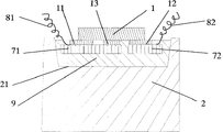
Fig. 1 is the encapsulating structure schematic diagram of LED lighting source in the prior art, illustrated the approach of heat when cooling base 2 transmits that led chip 1 produces among the figure.The heat that led chip 1 produces through its both positive and negative polarity pin 11,12 with and heat sink 13 copper-clad 3, insulating barrier 4, aluminum base layer 5, heat-conducting silicone greases 6 that are delivered to successively on the aluminium base of bottom, at last to cooling base 2.
Fig. 2~shown in Figure 3, the encapsulating structure of the LED lighting source of two embodiment of the utility model, led chip 1 are installed on the end face of cooling base 2.When led chip 1 belongs to thermoelectricity that the heat sink and anodal pin of thermoelectric separate type or bottom links to each other not during separate type, its negative pole pin 12 is welded on the copper sheet 72, and heat sink 13 of its anodal pin 11 and bottom is welded on the copper sheet 71, as shown in Figure 2.When led chip 1 belongs to the heat sink thermoelectricity that links to each other with the negative pole pin of thermoelectric separate type or bottom not during separate type, heat sink 13 of its negative pole pin 12 and bottom is welded on the copper sheet 72, and its anodal pin is welded on the copper sheet 71, as shown in Figure 3.Be welded with lead 81 and 82 on copper sheet 71 and 72 respectively, these two leads 81 and 82 are used for realizing the effect that is electrically connected with external circuits.Cooling base 2 is to be made by aluminum or aluminum alloy.Cooling base 2 offers the platform 21 of a depression in the upper surface that led chip 1 is installed, surface applied skim boron nitride 9 at depression platform 21, after treating its cooled and solidified, continue to inject boron nitride 9 again, before these boron nitride 9 cooled and solidified, the copper sheet 71,72 that is welded with led chip 1 is embedded in this boron nitride 9, and cooled and solidified.Boron nitride 9 had both played good conductive force, also played the effect of fixed L ED chip 1.
In the utility model, be better heat radiation, copper sheet 71,72 and insulating heat-conductive layer can be made enough approaching by the boron nitride 9 as shown in embodiment, but in design, the selection of this thickness should not influence pin 11,12 and the lead 81,82 that welds led chip on copper sheet 71 and 72 respectively, do not influence boron nitride 9 existing conductive force, the effect of fixed L ED chip 1 again yet.
Fig. 4 is another embodiment of the utility model, and different with first and second embodiment is that led chip is that two LEDs chips 14,15 are composed in series.The copper sheet 171 that welds on the anodal pin 151 of the copper sheet 162 of welding and led chip 15 on the negative pole pin 142 of led chip 14 is connected by lead 183, is welded with lead 181 and 182 respectively on the copper sheet 172 of welding on the negative pole pin 152 of the copper sheet 161 of welding and led chip 15 on the anodal pin 141 of led chip 14 and is used to be connected external circuit.Certainly, also three or above led chip can be formed lighting source by series-parallel form, its structure and principle are same as the previously described embodiments.
Claims (9)
1. the encapsulating structure of a LED lighting source, comprise led chip and the cooling base that led chip is installed, it is characterized in that: the heat sink and both positive and negative polarity pin of described led chip bottom is welded on respectively on the different copper sheets, be respectively arranged with the parts that are used to be electrically connected on the described copper sheet that is welded with led chip both positive and negative polarity pin, described copper sheet embeds in the insulating heat-conduction material that described cooling base upper surface is provided with.
2. the encapsulating structure of LED lighting source according to claim 1 is characterized in that: described led chip is single LEDs chip, and the parts that are used to be electrically connected on the described copper sheet are leads.
3. the encapsulating structure of LED lighting source according to claim 1, it is characterized in that: described led chip is electrically connected for the plurality of LEDs chip, pad welding by being provided with on its copper sheet between the adjacent LED chip or connect by lead is provided with the lead that is electrically connected with external circuits on the copper sheet of the led chip at circuit two ends.
4. the encapsulating structure of LED lighting source according to claim 1 is characterized in that: described led chip is a not separate type of thermoelectric separate type or thermoelectricity.
5. the encapsulating structure of LED lighting source according to claim 4, it is characterized in that: described led chip is a not separate type of thermoelectricity, it is heat sink to link to each other with the negative pole pin, and the copper sheet that described welding led chip bottom is heat sink can be one with the copper sheet of welding led chip negative pole pin.
6. the encapsulating structure of LED lighting source according to claim 4, it is characterized in that: described led chip is a not separate type of thermoelectricity, it is heat sink to link to each other with anodal pin, and the copper sheet that described welding led chip bottom is heat sink can be one with the copper sheet of the anodal pin of welding led chip.
7. the encapsulating structure of LED lighting source according to claim 1 is characterized in that: described cooling base one end face is provided with a depression platform, and described insulating heat-conduction material injects described depression platform.
8. according to the encapsulating structure of claim 1 or 7 described LED lighting sources, it is characterized in that: described insulating heat-conduction material is pottery or boron nitride.
9. according to the encapsulating structure of claim 1 or 7 described LED lighting sources, it is characterized in that: described cooling base is an aluminum or aluminum alloy.
Priority Applications (1)
| Application Number | Priority Date | Filing Date | Title |
|---|---|---|---|
| CN2010201196524U CN201732809U (en) | 2010-02-02 | 2010-02-02 | Encapsulating structure of LED lighting source |
Applications Claiming Priority (1)
| Application Number | Priority Date | Filing Date | Title |
|---|---|---|---|
| CN2010201196524U CN201732809U (en) | 2010-02-02 | 2010-02-02 | Encapsulating structure of LED lighting source |
Publications (1)
| Publication Number | Publication Date |
|---|---|
| CN201732809U true CN201732809U (en) | 2011-02-02 |
Family
ID=43523964
Family Applications (1)
| Application Number | Title | Priority Date | Filing Date |
|---|---|---|---|
| CN2010201196524U Expired - Lifetime CN201732809U (en) | 2010-02-02 | 2010-02-02 | Encapsulating structure of LED lighting source |
Country Status (1)
| Country | Link |
|---|---|
| CN (1) | CN201732809U (en) |
Cited By (2)
| Publication number | Priority date | Publication date | Assignee | Title |
|---|---|---|---|---|
| CN102141232A (en) * | 2010-02-02 | 2011-08-03 | 上海三思电子工程有限公司 | LED illumination light source encapsulation structure and manufacturing method thereof |
| CN102322583A (en) * | 2011-09-13 | 2012-01-18 | 上海三思电子工程有限公司 | High-power LED (light-emitting diode) bulb light |
-
2010
- 2010-02-02 CN CN2010201196524U patent/CN201732809U/en not_active Expired - Lifetime
Cited By (3)
| Publication number | Priority date | Publication date | Assignee | Title |
|---|---|---|---|---|
| CN102141232A (en) * | 2010-02-02 | 2011-08-03 | 上海三思电子工程有限公司 | LED illumination light source encapsulation structure and manufacturing method thereof |
| CN102322583A (en) * | 2011-09-13 | 2012-01-18 | 上海三思电子工程有限公司 | High-power LED (light-emitting diode) bulb light |
| CN102322583B (en) * | 2011-09-13 | 2014-12-10 | 上海三思电子工程有限公司 | High-power LED (light-emitting diode) bulb light |
Similar Documents
| Publication | Publication Date | Title |
|---|---|---|
| CN203481273U (en) | LED light source module based on AlSiC composite substrate | |
| CN201349020Y (en) | Packaged large-power LED with radiator | |
| CN101692448A (en) | Multi-chip LED centralized-encapsulated radiating structure and encapsulation technology thereof | |
| CN201232984Y (en) | Radiating module for LED lamp | |
| CN203521475U (en) | Floating heat radiation copper sheet support used for LED flip chip packaging and LED packaging member | |
| CN201732809U (en) | Encapsulating structure of LED lighting source | |
| TW201349577A (en) | Illuminating device | |
| TW201608678A (en) | Chip package module and package substrate | |
| CN102842671B (en) | LED (Light Emitting Diode) heat dissipation structure and machining method thereof | |
| CN201804911U (en) | LED chip with ceramic substrate | |
| CN201629332U (en) | Multi-chip LED package radiating structure | |
| CN205248302U (en) | LED photo engine structure | |
| CN203323067U (en) | High-power LED heat dissipation structure | |
| CN103887396A (en) | A light-emitting assembly in which an LED chip is directly welded to the surface of a copper heat sink and a preparation method thereof | |
| CN203746850U (en) | High-efficiency LED module group device capable of omnibearing light emission | |
| CN201985161U (en) | Stack-type thermal module | |
| CN202101047U (en) | High-power LED (light-emitting diode) light source module with excellent heat dissipation performance | |
| CN202065723U (en) | LED (light-emitting diode) lamp | |
| CN202203720U (en) | LED (light emitting diode) light source module | |
| CN206112536U (en) | Thermoelectric separation light -emitting diode (LED) | |
| TW201212306A (en) | LED heat-conduction substrate and heat-dissipation module structure | |
| CN202013885U (en) | LED (Light Emitting Diode) integrated packaging device arranged at upper and lower of electrode | |
| CN205264751U (en) | Low thermal resistance LED light source | |
| CN102141232A (en) | LED illumination light source encapsulation structure and manufacturing method thereof | |
| CN200996590Y (en) | LEd light |
Legal Events
| Date | Code | Title | Description |
|---|---|---|---|
| C14 | Grant of patent or utility model | ||
| GR01 | Patent grant | ||
| CX01 | Expiry of patent term |
Granted publication date: 20110202 |
|
| CX01 | Expiry of patent term |