CN201655863U - Mixed battery exchange device - Google Patents
Mixed battery exchange device Download PDFInfo
- Publication number
- CN201655863U CN201655863U CN2010201147903U CN201020114790U CN201655863U CN 201655863 U CN201655863 U CN 201655863U CN 2010201147903 U CN2010201147903 U CN 2010201147903U CN 201020114790 U CN201020114790 U CN 201020114790U CN 201655863 U CN201655863 U CN 201655863U
- Authority
- CN
- China
- Prior art keywords
- battery
- storage tank
- tank group
- ccontaining
- accommodating groove
- Prior art date
- Legal status (The legal status is an assumption and is not a legal conclusion. Google has not performed a legal analysis and makes no representation as to the accuracy of the status listed.)
- Expired - Fee Related
Links
Images


Classifications
-
- Y—GENERAL TAGGING OF NEW TECHNOLOGICAL DEVELOPMENTS; GENERAL TAGGING OF CROSS-SECTIONAL TECHNOLOGIES SPANNING OVER SEVERAL SECTIONS OF THE IPC; TECHNICAL SUBJECTS COVERED BY FORMER USPC CROSS-REFERENCE ART COLLECTIONS [XRACs] AND DIGESTS
- Y02—TECHNOLOGIES OR APPLICATIONS FOR MITIGATION OR ADAPTATION AGAINST CLIMATE CHANGE
- Y02E—REDUCTION OF GREENHOUSE GAS [GHG] EMISSIONS, RELATED TO ENERGY GENERATION, TRANSMISSION OR DISTRIBUTION
- Y02E60/00—Enabling technologies; Technologies with a potential or indirect contribution to GHG emissions mitigation
- Y02E60/10—Energy storage using batteries
Abstract
The utility model relates to a mixed battery exchange device, which comprises at least one battery accommodation column module, at least one pair of rails and at least one battery moving and plugging arm, wherein the battery accommodation column module comprises a plurality of first accommodation groove assemblies and second accommodation groove assemblies; the peripheries of the first accommodation groove assemblies and the second accommodation groove assemblies are provided with a plurality of first connecting parts and second connecting parts, so that the first accommodation groove assemblies and the second accommodation groove assemblies are correspondingly connected and combined by the first connecting parts and the second connecting parts; the first accommodation groove assemblies and the second accommodation groove assemblies are internally provided with a plurality of battery accommodation grooves; the battery accommodation grooves of the first accommodation groove assemblies are internally provided with at least one charging seat; the pair of rails are arranged at the upper and lower ends of one side of the battery accommodation column module; and the battery moving and plugging arm is arranged between the two rails and moves among the first accommodation groove assemblies or the second accommodation groove assemblies of the two battery accommodation column modules along tracks of the two rails. The mixed battery exchange device can rapidly supplement masses of rechargeable batteries.
Description
Technical field
The utility model relates to a kind of hybrid battery switch, relates in particular to a kind ofly to be applied to electric vehicle battery fixed point exchange, and has hybrid battery charging or the simple ccontaining operator scheme of battery, with the device of access with the operation of exchange rechargeable battery.
Background technology
Motor vehicle replaces one of green energy running vehicle of high dirt and oil consumption automobile for utmost point desire, but no matter be electric motor car or electric automobile, topmost key component is the rechargeable battery as the driving dynamics energy, because it is too high that the equipment and the soil cost of charging station are set, the electric vehicle charging station can't be popularized with a large amount of and be provided with, and is the root-cause that the retardance motor vehicle generalizes.
Therefore, there is the scheme of many solutions therefore to give birth to because of fortune, such as No. 412095 " mobile battery charging and switch " novel patent case of TaiWan, China patent gazette, the then preliminary embryo technology that discloses about the rechargeable battery exchange, but the hardware configuration of existing vehicular mobile battery switching station like that, in the road that travels, produce vibrations because of jolting of track is uneven, cause being used in the case mechanical arm (robot arm) of mobile charging battery when carrying out the displacement operation of rechargeable battery, easily lose precision, and cause problem when the machine fault, so plant the design of existing vehicular mobile battery switching station, in the problem of mechanically actuated operation precision and shock resistance ability, can't be done effectively and low-cost solve before, and be difficult for being widely applied and offer the industry utilization.
In addition, as considering the battery swap system of the formula that resides in fixed point, as No. 344159 " centralized battery keeping and charging device " novel patent case of middle Taiwan state's patent gazette, do not understand the mechanical arm precision that produces though have above-mentioned mobile battery charging and switch, problem that shock resistance ability and cost are high and shortcoming, but lack in response to rechargeable battery reciprocal exchange of business amount motor-driven and scheduling flexibility ratio required when frequent, for example: using motor vehicle quantity and the higher place of density, have the rechargeable battery exchange capacity of frequent and excess, then above-mentioned existing fixed point resides in formula rechargeable battery switching system and structure, sufficient rechargeable battery supply can't be provided real-time, lack rechargeable battery scheduling adaptability to changes, cause inconvenience and the puzzlement of user in the rechargeable battery exchange, also can't meet demand and economic benefit that industry is utilized.
The utility model content
Technical problem underlying to be solved in the utility model is, overcome easy generation mechanical arm vibrations displacement out-of truth problem and shortcoming that prior art exists, and the existing formula switch pond that fixedly resides in can't be dealt with the problem that a large amount of rechargeable batteries exchange motor-driven and real-time, and the industry that can't offer is made the effectively defective of utilization, and provide a kind of hybrid battery switch, can replenish a large amount of rechargeable batteries fast, and can not produce problem and shortcoming that battery moves plug arm vibrations shift affects accuracy, can eliminate problem and shortcoming that existing vehicle-mounted removable or fixing fixed point reside in the formula switch fully, while also has this both advantage concurrently, to solve motor vehicle rechargeable battery charging of accumulating for a long time and the problem that exchanges.
The technical scheme that its technical problem that solves the utility model adopts is:
A kind of hybrid battery switch, it is characterized in that, comprise: the ccontaining row module of at least one battery, comprise some several the first storage tank groups and the second storage tank group, this the first storage tank group and the second storage tank group are provided with some first connecting portions and second connecting portion in periphery, make between the first storage tank group or the second storage tank group and to borrow that this first connecting portion and second connecting portion are corresponding to be linked and make up, be provided with some battery accommodating groove in this first storage tank group and the second storage tank group, be provided with at least one cradle in the battery accommodating groove of this first storage tank group, for the ccontaining charging of at least one rechargeable battery, the battery accommodating groove of this second storage tank group is ccontaining at least one rechargeable battery; At least one pair of track is located at the ccontaining row module one side upper and lower end of this battery; At least one battery moves the plug arm, be located between two tracks, track along this two track is displaced between each first storage tank group or the second storage tank group of the ccontaining row module of two batteries, moves the swap operation that the plug arm shifts out or stores each rechargeable battery in each battery accommodating groove of the rechargeable battery in each battery accommodating groove of each first storage tank group or the second storage tank group by this battery.
Aforesaid hybrid battery switch, wherein first connecting portion of the first storage tank group is a pin.
Aforesaid hybrid battery switch, wherein second connecting portion of the first storage tank group is a groove.
Aforesaid hybrid battery switch, wherein first connecting portion of the second storage tank group is a pin.
Aforesaid hybrid battery switch, wherein second connecting portion of the second storage tank group is a groove.
Aforesaid hybrid battery switch, wherein battery move the plug arm comprise: at least one guide rail is linked to two interorbitals; At least one guide rail driver drives this guide rail and carries out upper and lower vertical moving along the track of this track; And at least one battery grabber, be incorporated on this guide rail, make this battery grabber carry out forward and backward moving axially along this guiderail track, and this battery grabber and left or right grasps rechargeable battery that the rechargeable battery that is full of electric weight maybe exhausts the electric weight of exchange and sends in each battery accommodating groove of the battery accommodating groove of each the first storage tank group in the ccontaining row module of battery or the second storage tank group ccontaining in the battery accommodating groove of each the first storage tank group in the ccontaining row module of the battery of both sides or each battery accommodating groove of the second storage tank group.
The effect of hybrid battery switch of the present utility model, be first connecting portion of the first storage tank group in the ccontaining row module of battery or the second storage tank group and the corresponding connecting structure of second connecting portion, allow the user change and done the flexible combination allotment according to the rechargeable battery exchange capacity, can not need vehicle-mounted moving at fixed position, can replenish a large amount of rechargeable batteries fast, and can not produce problem and shortcoming that battery moves plug arm vibrations shift affects accuracy, can eliminate problem and shortcoming that above-mentioned existing vehicle-mounted removable or fixing fixed point reside in the formula switch fully, while also has this both advantage concurrently, to solve motor vehicle rechargeable battery charging of accumulating for a long time and the problem that exchanges.
Description of drawings
Below in conjunction with drawings and Examples the utility model is further specified.
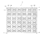
Fig. 1 is the vertical view of the utility model hybrid battery switch first embodiment;
Fig. 2 is the front view of the utility model hybrid battery switch first embodiment;
Fig. 3 is the front view of the first storage tank group shown in Figure 1;
Fig. 4 is the front view of the second storage tank group shown in Figure 1;
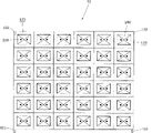
Fig. 5 is that second of the utility model hybrid battery switch is implemented illustration;
Fig. 6 is a vertical view shown in Figure 5, shows that this battery moves the state that the plug arm grasped or placed rechargeable battery to the left or to the right
Fig. 7 is the preferred application illustration of the utility model hybrid battery switch.
The number in the figure explanation:
The ccontaining row module of 100 hybrid battery switches, 10 batteries
11 first storage tank groups, 111 first connecting portions
112 second connecting portions, 113 battery accommodating groove
114 cradles, 12 second storage tank groups
121 first connecting portions, 122 second connecting portions
123 battery accommodating groove, 20 tracks
30 batteries move plug arm 31 guide rails
32 guide rail drivers, 33 battery grabbers
200 rechargeable batteries 300 replenish vehicle
310 replenish railway platform 320 replenishes railway platform
Embodiment
See also Fig. 1, Fig. 2, Fig. 3 and shown in Figure 4, first embodiment for hybrid battery switch 100 of the present utility model, this hybrid battery switch 100 comprises the ccontaining row module 10 of at least one battery, the ccontaining row module 10 of this battery comprises some several the first storage tank groups 11 and the second storage tank group 12, this first storage tank group 11 is provided with some first connecting portions 111 and second connecting portion 112 in periphery, the pattern of this first connecting portion 111 and second connecting portion 112 is not limit, be to be that the pin and second connecting portion 112 are that groove is an example in the utility model with first connecting portion 111, the syndeton that other equivalence is corresponding, when not taking off category of the present utility model, between each first storage tank group 11, by this first connecting portion 111 and the 112 corresponding bindings of second connecting portion, 11 of the first storage tank groups can be done as storehouse combination (as shown in Figure 2) longitudinally, be provided with some battery accommodating groove 113 in each first storage tank group 11, at least be provided with a cradle 114 in this battery accommodating groove 113, be placed in this battery accommodating groove 113 at least one rechargeable battery 200 and carry out charging operations.
This second storage tank group 12 is provided with some first connecting portions 121 and second connecting portion 122 in periphery, the pattern of this first connecting portion 121 and second connecting portion 122 is not limit, be to be that the pin and second connecting portion 122 are that groove is an example in the utility model with first connecting portion 121, the syndeton that other equivalence is corresponding, when not taking off category of the present utility model, between each second storage tank group 12, by this first connecting portion 121 and the 122 corresponding bindings of second connecting portion, 12 of the first storage tank groups can be done as storehouse combination (as shown in Figure 2) longitudinally, and, between this first storage tank group 11 and the second storage tank group 12, also can be by the corresponding combination between this first connecting portion 111 and second connecting portion 122, and do as storehouse combination (as shown in Figure 2) longitudinally, be provided with some battery accommodating groove 123 in each second storage tank group 12, can be ccontaining in each battery accommodating groove 113 at least one rechargeable battery 200.
Combination between first above-mentioned storage tank group 11 and the combination between the first storage tank group 11 or the second storage tank group 12 and the second storage tank group 12, the perhaps combination between the first storage tank group 11 and the second storage tank group 12 is not limited to above-mentioned endwise piling stack combination kenel.
At least one pair of track 20 is located at the ccontaining row module 10 1 side upper and lower ends of this battery, in the utility model is to enumerate to be arranged at upper and lower end between the two adjacent ccontaining row modules 10 of battery.
At least one battery moves plug arm 30, be located between two tracks 20, can be along the track of this two track 20, be displaced between each the first storage tank group 11 or the second storage tank group 12 between the ccontaining row module 10 of two batteries, move the swap operation that each rechargeable battery 200 in each battery accommodating groove 123 of the rechargeable battery 200 in each battery accommodating groove 113 of 30 pairs of each first storage tank groups 11 of plug arm or the second storage tank group 12 shift out or store by this battery.
Above-mentioned track 20 and battery move the structure of 30 of arms of plug, not with Fig. 1 to shown in Figure 4 exceeding, be other equivalent three dimensions moving track and mechanical arm structure such as, when not taking off category of the present utility model.
Please cooperate Fig. 5 and shown in Figure 6 again, second embodiment for hybrid battery switch 100 of the present utility model, wherein, show this pair of tracks 20 straight perpendicular respectively be arranged at 10 of the ccontaining row modules of two batteries before, the rear, this battery moves plug arm 30 and comprises at least one guide rail 31, at least one guide rail driver 32 and at least one battery grabber 33, wherein, this guide rail 31 is linked to 20 on two tracks, this guide rail driver 32 is located at the front or rear side of 10 of the ccontaining row modules of two batteries, to drive on this guide rail 31 carries out along the track of this track 20, following vertical moving (shown in the direction of arrow among Fig. 5), this battery grabber 33 is incorporated on this guide rail 31, before this battery grabber 33 is carried out along these guide rail 31 tracks, axially move the back, and this battery grabber 33 and left or right (shown in the direction of arrow among Fig. 6), grasp in each battery accommodating groove 123 of the battery accommodating groove 113 of each the first storage tank group 11 in the ccontaining row module 10 of the battery of both sides or the second storage tank group 12 rechargeable battery 200 that the rechargeable battery 200 that is full of electric weight maybe exhausts the electric weight of exchange send in each battery accommodating groove 123 of the battery accommodating groove 113 of each the first storage tank group 11 in the ccontaining row module 10 of battery or the second storage tank group 12 ccontaining, to reach effect as the described three dimensions battery swap of above-mentioned first embodiment.
Please cooperate shown in Figure 7 again, preferred application example for hybrid battery switch 100 of the present utility model, wherein, show when needing additional a large amount of fast rechargeable battery 200, then carrying several second storage tank groups 12 by an additional vehicle 300 replenishes in the ccontaining row module of each battery 10 outsides, be to be recited in the ccontaining row module of two batteries 10 outsides to be provided with one respectively and to replenish railway platform 310 and 320 and carry out operation, all ccontaining rechargeable battery 200 that is full of electric weight in each battery accommodating groove 113 in each second storage tank group 12 in the utility model.
Between the above-mentioned first storage tank group 11 and the first storage tank group 11, or second between storage tank group 12 and the second storage tank group 12, perhaps between the first storage tank group 11 and the second storage tank group 12, all can pass through this first connecting portion 111,121 and second connecting portion 112,122 corresponding connecting structure, and having been exchanged the rechargeable battery 200 quantity second storage tank group 12 totally, former prior in the ccontaining row module of two batteries 10 each hang or be pulled away from the ccontaining row module 10 of battery to this additional railway platform 310 or 320, and directly will replenish each second new storage tank group 12 in the vehicle 300 hang in combination be linked to the first storage tank group 11 of the ccontaining row module 10 of this battery or the second storage tank group 12 on, above-mentioned 12 old of the second storage tank groups in replenishing railway platform 310 or 320 hang in again replenishes in the vehicle 300, operation can be full of the rechargeable battery 200 of electric weight fast in a large number whereby, with can't be in response to the states of a large amount of exchanges in response to rechargeable battery 200 quantity in original ccontaining row module 10 of each battery, or the tediously long state that can't exchange in response to a large amount of rechargeable batteries 200 moment of each 200 charging interval of rechargeable battery in this first storage tank group 11.
The above, it only is preferred embodiment of the present utility model, be not that the utility model is done any pro forma restriction, every foundation technical spirit of the present utility model all still belongs in the scope of technical solutions of the utility model any simple modification, equivalent variations and modification that above embodiment did.
Claims (6)
1. a hybrid battery switch is characterized in that, comprising:
The ccontaining row module of at least one battery, comprise some several the first storage tank groups and the second storage tank group, this the first storage tank group and the second storage tank group are provided with some first connecting portions and second connecting portion in periphery, make between the first storage tank group or the second storage tank group and to borrow that this first connecting portion and second connecting portion are corresponding to be linked and make up, be provided with some battery accommodating groove in this first storage tank group and the second storage tank group, be provided with at least one cradle in the battery accommodating groove of this first storage tank group, for the ccontaining charging of at least one rechargeable battery, the battery accommodating groove of this second storage tank group is ccontaining at least one rechargeable battery;
At least one pair of track is located at the ccontaining row module one side upper and lower end of this battery;
At least one battery moves the plug arm, be located between two tracks, track along this two track is displaced between each first storage tank group or the second storage tank group of the ccontaining row module of two batteries, moves the swap operation that the plug arm shifts out or stores each rechargeable battery in each battery accommodating groove of the rechargeable battery in each battery accommodating groove of each first storage tank group or the second storage tank group by this battery.
2. hybrid battery switch according to claim 1 is characterized in that: first connecting portion of the described first storage tank group is a pin.
3. hybrid battery switch according to claim 1 is characterized in that: second connecting portion of the described first storage tank group is a groove.
4. hybrid battery switch according to claim 1 is characterized in that: first connecting portion of the described second storage tank group is a pin.
5. hybrid battery switch according to claim 1 is characterized in that: second connecting portion of the described second storage tank group is a groove.
6. hybrid battery switch according to claim 1 is characterized in that: described battery moves the plug arm and comprises:
At least one guide rail is linked to two interorbitals;
At least one guide rail driver drives this guide rail and carries out upper and lower vertical moving along the track of this track; And
At least one battery grabber, be incorporated on this guide rail, make this battery grabber carry out forward and backward moving axially along this guiderail track, and this battery grabber and left or right grasps rechargeable battery that the rechargeable battery that is full of electric weight maybe exhausts the electric weight of exchange and sends in each battery accommodating groove of the battery accommodating groove of each the first storage tank group in the ccontaining row module of battery or the second storage tank group ccontaining in the battery accommodating groove of each the first storage tank group in the ccontaining row module of the battery of both sides or each battery accommodating groove of the second storage tank group.
Priority Applications (1)
| Application Number | Priority Date | Filing Date | Title |
|---|---|---|---|
| CN2010201147903U CN201655863U (en) | 2010-02-21 | 2010-02-21 | Mixed battery exchange device |
Applications Claiming Priority (1)
| Application Number | Priority Date | Filing Date | Title |
|---|---|---|---|
| CN2010201147903U CN201655863U (en) | 2010-02-21 | 2010-02-21 | Mixed battery exchange device |
Publications (1)
| Publication Number | Publication Date |
|---|---|
| CN201655863U true CN201655863U (en) | 2010-11-24 |
Family
ID=43121106
Family Applications (1)
| Application Number | Title | Priority Date | Filing Date |
|---|---|---|---|
| CN2010201147903U Expired - Fee Related CN201655863U (en) | 2010-02-21 | 2010-02-21 | Mixed battery exchange device |
Country Status (1)
| Country | Link |
|---|---|
| CN (1) | CN201655863U (en) |
Cited By (4)
| Publication number | Priority date | Publication date | Assignee | Title |
|---|---|---|---|---|
| CN103762629A (en) * | 2013-12-27 | 2014-04-30 | 顾连芳 | Device of battery interchanger |
| CN103777564A (en) * | 2013-12-27 | 2014-05-07 | 顾连芳 | Voice activated battery switch device |
| CN108349394A (en) * | 2015-11-04 | 2018-07-31 | 江森自控科技公司 | Hybrid battery control system architecture design system and method |
| CN109795301A (en) * | 2019-01-02 | 2019-05-24 | 北京汽车股份有限公司 | Batteries of electric automobile packet, electric car and electrical changing station |
-
2010
- 2010-02-21 CN CN2010201147903U patent/CN201655863U/en not_active Expired - Fee Related
Cited By (4)
| Publication number | Priority date | Publication date | Assignee | Title |
|---|---|---|---|---|
| CN103762629A (en) * | 2013-12-27 | 2014-04-30 | 顾连芳 | Device of battery interchanger |
| CN103777564A (en) * | 2013-12-27 | 2014-05-07 | 顾连芳 | Voice activated battery switch device |
| CN108349394A (en) * | 2015-11-04 | 2018-07-31 | 江森自控科技公司 | Hybrid battery control system architecture design system and method |
| CN109795301A (en) * | 2019-01-02 | 2019-05-24 | 北京汽车股份有限公司 | Batteries of electric automobile packet, electric car and electrical changing station |
Similar Documents
| Publication | Publication Date | Title |
|---|---|---|
| CN201769792U (en) | Vehicle-mounted battery replacement system | |
| CN201655863U (en) | Mixed battery exchange device | |
| CN203237020U (en) | Electric vehicle with battery replaced in vehicle bottom continuous move mode and device for replacing battery thereof | |
| CN204688082U (en) | What apply shuttle changes electric system | |
| CN102267437B (en) | Fast power transformation station of battery box of electric automobile and replacement method of battery box | |
| CN103241111A (en) | Electric vehicle with battery replaced by adopting vehicle bottom lateral linkage and device for battery replacement | |
| CN201918754U (en) | Parallel charging device for multiple power batteries | |
| CN109278722A (en) | A kind of electric car shares battery system and changes method for electrically | |
| CN108487749A (en) | A kind of mechanical type three-dimensional parking garage | |
| CN217672235U (en) | Compact power station | |
| CN209719540U (en) | Battery for electric charging station accesses system and electric charging station | |
| CN106515679A (en) | Battery replacing robot with temporary battery storage rack and battery replacing method of battery replacing robot | |
| CN111852133A (en) | Modularized stereo garage capable of charging electric automobile | |
| CN114379415A (en) | Battery replacement station for electric vehicle and battery management method | |
| CN208267492U (en) | A kind of mechanical type three-dimensional parking garage | |
| CN103407379B (en) | Centralized initiative balancing device for electric vehicle battery management system | |
| CN201590461U (en) | Fixed battery exchanging device | |
| CN109216614A (en) | A kind of cell fixing device of large car electrical changing station | |
| CN2928579Y (en) | Solar energy electric vehicle | |
| CN211139282U (en) | Circumferentially-arranged multi-lane battery replacement station | |
| CN210634533U (en) | Heavy truck battery replacement station | |
| CN208112271U (en) | Battery charger, battery storage frame and battery operating platform | |
| CN105882432A (en) | Intelligent power up system of electric vehicle | |
| CN209454717U (en) | Fast quick change electric system | |
| CN110316162A (en) | A kind of quick plug-in charging storehouse and electrical changing station |
Legal Events
| Date | Code | Title | Description |
|---|---|---|---|
| C14 | Grant of patent or utility model | ||
| GR01 | Patent grant | ||
| C17 | Cessation of patent right | ||
| CF01 | Termination of patent right due to non-payment of annual fee |
Granted publication date: 20101124 Termination date: 20140221 |