CN201647872U - Hoisting mechanism of single hoisting point foundry crane - Google Patents
Hoisting mechanism of single hoisting point foundry crane Download PDFInfo
- Publication number
- CN201647872U CN201647872U CN2010201773146U CN201020177314U CN201647872U CN 201647872 U CN201647872 U CN 201647872U CN 2010201773146 U CN2010201773146 U CN 2010201773146U CN 201020177314 U CN201020177314 U CN 201020177314U CN 201647872 U CN201647872 U CN 201647872U
- Authority
- CN
- China
- Prior art keywords
- retarder
- drum coupling
- reel
- motor
- speed reducer
- Prior art date
- Legal status (The legal status is an assumption and is not a legal conclusion. Google has not performed a legal analysis and makes no representation as to the accuracy of the status listed.)
- Expired - Lifetime
Links
Images

Landscapes
- Carriers, Traveling Bodies, And Overhead Traveling Cranes (AREA)
Abstract
The utility model discloses a hoisting mechanism of a single hoisting point foundry crane, which relates to a foundry crane, solves the problem that a hoisting mechanism of the traditional single hoisting point foundry crane has high manufacturing cost and also meets the requirement of latest national safety standard. The hoisting mechanism is characterized in that two ends of a roller 1 are respectively connected with a left speed reducer 2-1 and a right speed reducer 2-2 through a roller coupling 3; the left speed reducer 2-1 and the right speed reducer 2-2 are respectively driven by a left motor 5-1 and a right motor 5-2; a roller coupling between the roller 1 and the left speed reducer 2-2 is a spherical hinge roller coupling 3-1; and a roller coupling between the roller 1 and the right speed reducer 2-2 is a spherical hinge roller coupling 3-2.
Description
Technical field
The utility model relates to ladle carne, particularly a kind of lifting mechanism of ladle carne.
Background technology
The lifting mechanism of single in the past suspension centre ladle carne adopts structure as shown in Figure 1, is made up of reel 1, retarder 2, drum coupling 3, drg 4, motor 5, drum shaft bearing 7, top sheave group 8.Adopt single motor, single retarder, single drum form, drive reel work by retarder by motor.Be characterized in simple in structure, cost is low.But slow-speed shaft has only power resources, as long as one zero, parts et out of order are arranged on the whole messenger chain, all can't work on, promptly can not finish a working cycle in the state of accident, if retarder generation breaking axis, can make lifting mechanism out of control, cause serious accident, so poor stability.
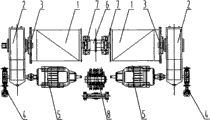
The up-to-date safety rate requirement of country, the hoisting crane of every handling guiding principle water bag must adopt between the slow-speed shaft rigidly connected lifting mechanism, can finish a working cycle in the state of accident.As shown in Figure 2, promptly be the lifting mechanism of a kind of double-motor, dual reducer, be rigidly connected between the slow-speed shaft, can finish the lifting mechanism of a working cycle in the state of accident.Form by reel 1, retarder 2, drum coupling 3, drg 4, motor 5, coupler 6, drum shaft bearing 7, top sheave group 8, adopt double-motor, dual reducer, two drum coupling, two reel, two drum shaft bearing, connect by coupler between the drum shaft bearing.This structure can satisfy up-to-date safety rate requirement, but complex structure, cost is higher.Not only want many two drum shaft bearings and a big coupler, and because the drum shaft bearing and between coupler take up room, make reel effectively use length to dwindle, must strengthen drum diameter, strengthen retarder, the suspender that matches simultaneously is also complicated, strengthened manufacturing cost.
Summary of the invention
The purpose of this utility model is exactly at the deficiencies in the prior art, and a kind of lifting mechanism of single suspension centre ladle carne is provided, and solves the existing high problem of single suspension centre ladle carne lifting mechanism manufacturing cost, can satisfy the requirement of national up-to-date safety rate simultaneously.
The technical solution of the utility model is:
A kind of lifting mechanism of single suspension centre ladle carne, by the motor-driven retarder, retarder is connected with reel by drum coupling, drg is arranged on the retarder side, reel is connected with the top sheave group with steel rope, it is characterized in that: the two ends of described reel are connected with right retarder with left retarder by described drum coupling respectively, described left retarder and right retarder are respectively by left motor and right motor-driven, drum coupling between described reel and the described left retarder is a kind of ball pivot drum coupling, and the drum coupling between described reel and the described right retarder is a kind of spherical roller drum coupling.
The utility model compared with prior art, owing to adopt double-motor, dual reducer, two drum coupling, single drum structure, motor drives reel work by retarder, drum coupling, it is the ball pivot drum coupling that respectively there are a drum coupling and one in the two ends of reel, one is the spherical roller drum coupling, so mechanism's slow-speed shaft is to be rigidly connected.During normal operation, drive reel work by two retarders of two driven by motor, when on one side motor or retarder or drg break down, can finish a working cycle by the driven by motor retarder of another side, this moment each zero, parts only need satisfy requirement of strength and get final product.Lifting mechanism than single suspension centre ladle carne in the past is safer.Owing to adopt the ball pivot drum coupling can retrain the longitudinal travel of roll device, adopt the spherical roller drum coupling can compensate the longitudinal travel of roll device, therefore more reasonable than the lifting mechanism of single suspension centre ladle carne in the past.
Description of drawings
Fig. 1 is the scheme drawing of a kind of single suspension centre ladle carne lifting mechanism of prior art;
Fig. 2 is the scheme drawing of another single suspension centre ladle carne lifting mechanism of prior art;
Fig. 3 is a structural representation of the present invention.
The utility model is further described by preferred embodiment below in conjunction with accompanying drawing.
The specific embodiment
As shown in Figure 3, a kind of lifting mechanism of single suspension centre ladle carne, drive retarder 2 by motor 5, retarder 2 is connected with reel 1 by drum coupling 3, drg 4 is arranged on retarder 2 sides, reel 1 usefulness steel rope is connected with top sheave group 8, the two ends of described reel 1 are connected with right retarder 2-2 with left retarder 2-1 by described drum coupling 3 respectively, described left retarder 2-1 and right retarder 2-2 are driven by left motor 5-1 and right motor 5-2 respectively, drum coupling between described reel 1 and the described left retarder 2-1 is a kind of ball pivot drum coupling 3-1, and the drum coupling between described reel 1 and the described right retarder 2-2 is a kind of spherical roller drum coupling 3-2.
Claims (1)
1. the lifting mechanism of a single suspension centre ladle carne, drive retarder (2) by motor (5), retarder (2) is connected with reel (1) by drum coupling (3), drg (4) is arranged on retarder (2) side, reel (1) is connected with top sheave group (8) with steel rope, it is characterized in that: the two ends of described reel (1) are connected with right retarder (2-2) with left retarder (2-1) by described drum coupling (3) respectively, described left retarder (2-1) and right retarder (2-2) are driven by left motor (5-1) and right motor (5-2) respectively, drum coupling between described reel (1) and the described left retarder (2-1) is a kind of ball pivot drum coupling (3-1), and the drum coupling between described reel (1) and the described right retarder (2-2) is a kind of spherical roller drum coupling (3-2).
Priority Applications (1)
| Application Number | Priority Date | Filing Date | Title |
|---|---|---|---|
| CN2010201773146U CN201647872U (en) | 2010-04-29 | 2010-04-29 | Hoisting mechanism of single hoisting point foundry crane |
Applications Claiming Priority (1)
| Application Number | Priority Date | Filing Date | Title |
|---|---|---|---|
| CN2010201773146U CN201647872U (en) | 2010-04-29 | 2010-04-29 | Hoisting mechanism of single hoisting point foundry crane |
Publications (1)
| Publication Number | Publication Date |
|---|---|
| CN201647872U true CN201647872U (en) | 2010-11-24 |
Family
ID=43113102
Family Applications (1)
| Application Number | Title | Priority Date | Filing Date |
|---|---|---|---|
| CN2010201773146U Expired - Lifetime CN201647872U (en) | 2010-04-29 | 2010-04-29 | Hoisting mechanism of single hoisting point foundry crane |
Country Status (1)
| Country | Link |
|---|---|
| CN (1) | CN201647872U (en) |
Cited By (2)
| Publication number | Priority date | Publication date | Assignee | Title |
|---|---|---|---|---|
| CN102718135A (en) * | 2012-06-21 | 2012-10-10 | 无锡市协兴港口机械有限公司 | Crane running mechanism |
| CN106744407A (en) * | 2016-12-13 | 2017-05-31 | 常熟市新亚机械制造有限公司 | A kind of powered hoist of reel easy to assemble |
-
2010
- 2010-04-29 CN CN2010201773146U patent/CN201647872U/en not_active Expired - Lifetime
Cited By (2)
| Publication number | Priority date | Publication date | Assignee | Title |
|---|---|---|---|---|
| CN102718135A (en) * | 2012-06-21 | 2012-10-10 | 无锡市协兴港口机械有限公司 | Crane running mechanism |
| CN106744407A (en) * | 2016-12-13 | 2017-05-31 | 常熟市新亚机械制造有限公司 | A kind of powered hoist of reel easy to assemble |
Similar Documents
| Publication | Publication Date | Title |
|---|---|---|
| CN201447317U (en) | Rotary hoisting frame electromagnetic crane | |
| CN201071261Y (en) | Bank bridge type permanent magnetism suspension wide and thick plate crane | |
| CN202492320U (en) | Chain hoist | |
| CN202864713U (en) | Ultrahigh-lift electric hoist | |
| CN201647872U (en) | Hoisting mechanism of single hoisting point foundry crane | |
| CN102864770A (en) | Efficient dynamic compaction machine | |
| CN102561277A (en) | Medium- and large-sized fixed winch hoist for spillway radial gates | |
| CN201217594Y (en) | Draw transmission mechanism with primary and secondary counterweight | |
| CN201961971U (en) | Large-tonnage dual-beam crane trolley | |
| CN204609396U (en) | For the Hoisting System of multi-storied garage crane | |
| CN201325823Y (en) | Novel hanger for large loop wheel machine | |
| CN201746181U (en) | Variable frequency energy-saving passenger-freight construction elevator | |
| CN201746271U (en) | Single hoisting point trolley and hoist employing same | |
| CN204847791U (en) | Four -wheel coordinated type lifting hook | |
| CN201128650Y (en) | Transitional sling | |
| CN208532044U (en) | A kind of new model electric hoist double-girder crane | |
| CN202466537U (en) | Middle-large surface hole arc gate fixed winch hoist | |
| CN203959702U (en) | A kind of duplex type cylinder safety crane | |
| CN203582132U (en) | Heavy paying-off rack for extra-high voltage stringing construction | |
| CN203319500U (en) | Reinforcing cage abutting-joint adjusting device | |
| CN201882820U (en) | Automatic jacking device for buffer rod of variable-amplitude auxiliary arm of wheel crane | |
| CN202924578U (en) | Special hoisting device for ship clearing machinery | |
| CN203320490U (en) | Double-roll four-connected arc door open-close machine | |
| CN204823963U (en) | Gantry crane oscillating keeps off rope ware | |
| CN110626467A (en) | Combined hydraulic anchor windlass |
Legal Events
| Date | Code | Title | Description |
|---|---|---|---|
| C14 | Grant of patent or utility model | ||
| GR01 | Patent grant | ||
| CX01 | Expiry of patent term |
Granted publication date: 20101124 |
|
| CX01 | Expiry of patent term |