Connecting rod with auto-action mechanism
Technical field
The utility model relates to a kind of component of window, relates in particular to a kind of linkage that is installed on window or the wing.
Background technology
Window is a kind of wing structure the most common on the building, normally as the ventilation and lighting mouth of building.Along with the development of modern building technology and the raising of user's requirement, people constantly improve the structure of window.
The opening ways of existing window comprises: flat open, push-and-pull, go up outstanding or outstanding down etc.In order to realize in use flexible of window, industry is designed the window with two kinds of opening ways, for example, has the double-open window of two kinds of opening ways of Ping Kai and push-and-pull simultaneously, as shown in Figure 1 to Figure 3.
Connecting rod is the common components of existing window, connects to be installed between sash and the window frame the action that finishing rotation and translation in the opening-closing process of sash.But simple rivet or bolt structure are usually adopted in the rotating shaft of existing connecting rod, move unsmooth and have some setbacks, thereby cause breakdown action not smooth of window or other wing structure.
In sum, there is the disappearance part in the linkage of existing window, is necessary to be improved.
Summary of the invention
In view of this, be necessary to provide the defective that has some setbacks at breakdown action in the prior art a kind of and have auto-action mechanism to realize the linkage of breakdown action smoothly.
In order to realize above-mentioned purpose, the technical solution of the utility model is as follows:
The utility model provides a kind of connecting rod with auto-action mechanism, comprise the frame connector that is connected in window frame, the fan connector that is connected in sash and an end to be articulated in this frame connector and the other end is articulated in the arm of this fan connector, on at least one spring is housed in this fan connector and this frame connector, this spring one end is fixed on this arm, props up to the other end coupling this fan connector and/or this frame connector; When this frame connector, this fan connector and this arm are positioned at the position of the closed condition of window, this spring stress distortion.
Preferably, be provided with a sleeve over against being matched with articulated position on this fan connector or this frame connector, this spring is a torsion spring, and this torsion spring set is contained on this sleeve, and this torsion spring one end is fixed on this arm, and the other end props up this fan connector or this frame connector.
Preferably, the hinged place of this arm and this frame connector, this fan connector has at least one to be provided with bearing.
Preferably, this frame connector is an assembly pulley, comprises pulley yoke, a plurality of pulley spindle and a plurality of pulley; These a plurality of pulley spindles are erected in this pulley yoke, and this pulley is sleeved on this pulley spindle rotationally; Enough spaces of leaving in this pulley yoke between this pulley are equipped with bearing, and this pulley yoke, this jointed shaft form by this bearing and be articulated and connected, and this jointed shaft is connected with this arm.
Preferably, this frame connector is a slide block.
Preferably, this fan connector is provided with the suit hole, is provided with to coupling the bolt apertures with internal thread on this arm; The hinged of the other end of this arm and this fan connector realized by adjustable jointed shaft, this adjustable jointed shaft comprises having externally threaded spiro union portion, external diameter is maximum and forms the saddle portion of support platform, the socket part in suit hole that is matched with this fan connector and the bearing connecting portion that is matched with this bearing in regular turn, the spiro union portion of this adjustable jointed shaft is bolted in the bolt apertures of this arm, this suit portion is inserted in the suit hole of this fan connector and this fan connector withstands in this saddle portion, and this bearing is inserted in the suit hole of this fan connector and is set in this bearing connecting portion.
Preferably, also be provided with axially extended adjusting pin-and-hole on this adjustable jointed shaft.
Preferably, this fan connector is provided with locating piece, coupling is right against this locating piece and is provided with locating bar on this arm, this locating bar is corresponding to the extreme position of the rotation of this fan connector, this fan connector turns to extreme position, this locating bar and this locating piece limit this fan connector and can not rotate again over against butt.
Preferably, this fan connector be provided with the tightening hole for holding screw be spirally connected plug-in mounting and and then should fan connector and be fixed on the sash; Also be provided with the installation base that is matched with sash on this fan connector.
Preferably, this arm is the supporting arm of load-bearing or the linking arm of not load-bearing.
Because adopt above-mentioned structure, the beneficial effects of the utility model are as follows:
1, the utility model utilizes the spring compressive deformation to produce precompose firmly, have auto-reset function, the operational forces of auto-action is provided, both can realize the automatic side-hung of sash, can whole sash be ejected automatically again, help realizing the push-and-pull of window.
The component that 2, can cooperate other, realize the opening and closing of window, particularly be applied to have the window of multiple opening ways, for example flatly open, the dual-purpose window of push-and-pull, rotational action corresponding to the required either large or small angle of different opening ways, all can realize very smooth and easyly, noise is extremely low, and the operator can implement the unlatching of the multiple mode of window easily.
3, because the design and the rotational action of spring auto-action obtains realizing very smoothly that linkage of the present utility model is applied to flatly open, the two opening ways windows of push-and-pull, than existingly flatly open, the dual-purpose window construction of push-and-pull is more energy-conservation.
4, adopt the design of pulley, make slip more smooth and easy, help the smooth and easy of switching motion.
5, regulate the design of pin-and-hole, can change the position that is spirally connected of adjustable jointed shaft and support arm, promptly change the spacing between positioning seat and the support arm, just can adjust the relative position of window frame and sash, compensative material deviation and installation deviation, easy to install.
Description of drawings
Below in conjunction with accompanying drawing,, will make the technical solution of the utility model and other beneficial effects apparent by detailed description to preferred embodiment of the present utility model.
In the accompanying drawing,
Fig. 1 opens for putting down, the schematic diagram of the closed condition of the dual-purpose window of push-and-pull;
Fig. 2 opens for putting down, the flat schematic diagram of opening opening of the dual-purpose window of push-and-pull;
Fig. 3 opens for putting down, the schematic diagram of the push-and-pull opening of the dual-purpose window of push-and-pull;
Fig. 4 is the stereogram of the connecting rod of embodiment 1 of the present utility model;
Fig. 5 is the stereogram of another angle of the connecting rod of embodiment 1 of the present utility model;
Fig. 6 is the stereogram of an angle again of the connecting rod of embodiment 1 of the present utility model;
Fig. 7 is the three-dimensional exploded view of the connecting rod of embodiment 1 of the present utility model;
Fig. 8 is the front view of the connecting rod of embodiment 1 of the present utility model;
Fig. 9 is the vertical view of the connecting rod of embodiment 1 of the present utility model;
Figure 10 is the generalized section of the connecting rod of embodiment 1 of the present utility model;
Figure 11 is the stereogram of the connecting rod of embodiment 2 of the present utility model;
Figure 12 is the stereogram of the connecting rod of embodiment 3 of the present utility model;
Figure 13 is the stereogram of the connecting rod of embodiment 4 of the present utility model.
In the accompanying drawing,
1 assembly pulley
11 pulley yokes, 12 pulley spindles, 13 pulleys
1 ' slide block
2 support arms
21 connecting holes, 22 bolt apertures, 23 installing holes, 24 installing holes
2 ' linking arm
3 positioning seats
33 locating pieces, 34 tightening holes, 31 sleeves, 32 suit holes, 35 holding screws
4 jointed shafts
5 adjustable jointed shafts
51 spiro union portions, 52 saddle portions, 53 socket parts, 54 bearing connecting portions 55 are regulated pin-and-hole
6 locating bars
7 resistance spring rods
8 springs
9 bearings
The specific embodiment
For further setting forth the utility model is to reach technological means and the effect that predetermined purpose is taked, see also following about detailed description of the present utility model and accompanying drawing, believe the purpose of this utility model, feature and characteristics, should obtain thus going deep into and concrete understanding, yet drawings and embodiments only provide reference and explanation usefulness, are not to be used for the utility model is limited.
Fig. 1 to Fig. 3 shows and a kind ofly common flatly opens, the dual-purpose window of push-and-pull, realizes opening with Ping Kai and push-and-pull dual mode.The accessory of window can be selected the pull bar in following each embodiment or the combination of a plurality of pull bars for use, cooperates other accessory to finish the switching motion of window
Upper and lower, left and right described in the utility model, top, the end are for the drawing of the Fig. 1 to Fig. 4 in the accompanying drawing, Fig. 7, Fig. 8 and Figure 11 to Figure 13, therefore do not limit protection domain of the present utility model.
[embodiment 1]
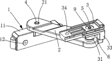
To shown in Figure 10, the linkage of present embodiment can be installed in the place, the lower right corner of sash as Fig. 4, as the bottom right connecting rod, comprises assembly pulley 1, support arm 2, positioning seat 3, jointed shaft 4, adjustable jointed shaft 5, locating bar 6, resistance spring rod 7, spring 8 and bearing 9.For the structure of positioning seat 3 is shown, linkage is not installed (and illustrating) spring 8 as yet among Fig. 4 among Fig. 4, and Fig. 5 to Figure 10 then installs (promptly showing) spring 8.
Assembly pulley 1 comprises pulley yoke 11, a plurality of pulley spindle 12 and a plurality of pulley 13; Pulley yoke 11 is a cavity housing that Open Side Down, and a plurality of (shown in the figure is two) pulley spindle 12 links are located between the front bulkhead and aft bulkhead of pulley yoke 11, and pulley 13 is sleeved on the pulley spindle 12 rotationally; The roof of pulley yoke 11 is provided with installing hole (also not shown among the figure) for jointed shaft 4 plug-in mountings; Enough spaces of leaving in the cavity of pulley yoke 11 between pulley 13 are equipped with bearing 9, and pulley yoke 11 is connected with the outer shroud of bearing 9;
Positioning seat 3 is one to be matched with the elongate body structure of sash, the bottom face of positioning seat 3 is provided with sleeve 31 ammunition feed springs 8 suits that extend downwards near the right-hand member place, be provided with the suit hole 32 of running through positioning seat 3 (comprising sleeve 31) up and down over against sleeve 31 on the positioning seat 3 and supply adjustable jointed shaft 5 and bearing 9 plug-in mountings, the right part of the bottom face of positioning seat 3 is extended downwards and is provided with a positioning block 33, on the positioning seat 3 near the left end place be provided with tightening hole 34 for holding screw 35 be spirally connected plug-in mounting and and then positioning seat 3 is fixed on the sash; The right-hand member of the top end face of positioning seat 3 also is provided with installation base;
Lower link (bottom right connecting rod and/or lower-left connecting rod) need play a part to support and load-bearing to sash, and therefore, support arm 2 is for having the elongate body structure of big thickness (design size according to actual needs); It is connecting hole 21 that one end of support arm 2 is provided with through hole, and the other end is provided with bolt apertures 22, and the inwall of bolt apertures 22 is provided with screw thread, and the both sides of bolt apertures 22 are respectively equipped with installing hole 23 and installing hole 24;
One end and the pulley yoke 11 of support arm 2 are hinged, hinged by jointed shaft 4 realizations, one end of jointed shaft 4 is inserted into from the installing hole on the top of pulley yoke 11 in the cavity of pulley yoke 11 and with the interior ring of bearing 9 and is connected, and the other end of jointed shaft 4 is plugged in the connecting hole 21 of support arm 2;
The other end of support arm 2 and positioning seat 3 are hinged, and be hinged by adjustable jointed shaft 5 realizations; Adjustable jointed shaft 5 comprises having externally threaded spiro union portion 51, external diameter is maximum and forms the saddle portion 52 of support platform, the socket part 53 in suit hole 32 that is matched with positioning seat 3 and the bearing connecting portion 54 that is matched with the interior ring of bearing 9 to the top end of from, and forming a multistage axis body, the bottom face of adjustable jointed shaft 5 also is provided with axially extended adjusting pin-and-hole 55 (referring to Figure 10); The spiro union portion 51 of adjustable jointed shaft 5 is bolted in the bolt apertures 22 of support arm 2, suit portion 53 is inserted in the suit hole 32 of positioning seat 3 and sleeve 31 withstands in saddle portion 52, bearing 9 is inserted in the suit hole 32 and is set in bearing connecting portion 54, and promptly the outer shroud of bearing 9 is connected in positioning seat 3 and interior ring is connected in adjustable jointed shaft 5;
Locating bar 6 is inserted in the installing hole 23 of supporting arm 2, installing hole 23 is corresponding to the extreme position of the rotation of positioning seat 3, be that positioning seat 3 turns to the limit specified position, the locating piece 33 of locating bar 6 and positioning seat 3 is over against butt, and restriction positioning seat 3 can not rotate to this direction again;
Spring 8 is a torsion spring, spring 8 is sleeved on the periphery (being sleeved on the sleeve 31) of the sleeve 31 of positioning seat 3 before support arm 2, positioning seat 3 and adjustable jointed shaft 5 are finished installation, spring 8 one ends are bent into hook-shaped, resistance spring rod 7 is inserted in the installing hole 24 of support arm 2 and is inserted in the hooked end of spring 8 and spring 8 is positioned supporting arm 2, and the other end of spring 8 props up the locating piece 33 of positioning seat 3; When assembly pulley 1, positioning seat 3 and support arm 2 are positioned at the position (common three members arrange point-blank) of the closed condition of window, spring 8 compressive deformations promptly impose the operational forces that precompose firmly produces auto-action.
Assembly pulley 1 is connected in window frame slidably as the frame connector, and the design of pulley makes draw rod device more smooth and easy with respect to the slip of window frame, helps the smooth and easy of switching motion; Positioning seat 3 is fixed in sash (also can be conversely with respect to the installation site of window frame and sash under suitable situation) as the fan connector; Support arm 2 is connected in assembly pulley 1 and positioning seat 3 in hinged mode respectively, and two hinged run-on points are equipped with bearing 9, when sash is being implemented switching motion, be that support arm 2 in the draw rod device is when implementing pivotal action with respect to assembly pulley 1 and positioning seat 3, owing to finish by bearing and to rotate and very smooth and easy and noise is extremely low, rotational action corresponding to the required either large or small angle of different opening ways, all can realize very smooth and easyly and do not hinder puckery, just the operator can implement the keying of the multiple mode of window easily, includes but not limited to be applied to flat opening, the dual-purpose window of push-and-pull.
The application of spring reaches compressive deformation in advance, has auto-reset function, produces the active force of auto-action, both can realize the automatic side-hung of sash, can whole sash be ejected automatically again, helps realizing the push-and-pull of window.
Because rotational action obtains realizing very smoothly and spring auto-action auxiliary, linkage of the present utility model is applied to flatly open, the two opening ways windows of push-and-pull, than existingly flatly open, the dual-purpose window construction of push-and-pull is more energy-conservation.
Certainly, the draw rod device of the present utility model window construction that is applied to single opening ways also has splendid effect.
In addition, utilize instrument to insert the adjusting pin-and-hole 55 of adjustable jointed shaft 5 and rotate adjustable jointed shaft 5, change the position that is spirally connected of adjustable jointed shaft 5 and support arm 2, promptly change the spacing between positioning seat 3 and the support arm 2, just can adjust the relative position of window frame and sash, compensative material deviation and installation deviation, easy to install.
In the present embodiment, spring 8 is installed between support arm 2 and the positioning seat 3, and the active force of auto-action is provided, and in like manner, spring 8 also can be installed between other frame connector such as support arm 2 and assembly pulley or slide block etc., and the active force of auto-action is provided.
[embodiment 2]
As shown in figure 11, the linkage of present embodiment can be installed in the lower right-hand corner of sash, as the lower-left connecting rod, for the structure of positioning seat 3 is shown, (and illustrating) spring 8 is not installed as yet among Figure 11.Upper right connecting rod among the structure of the lower-left connecting rod of present embodiment and operating principle and the embodiment 1 is basic identical, difference only is, in order to cooperate installation, the structure of positioning seat 3 slightly changes, positioning seat 3 is long than the positioning seat of embodiment 1, tightening hole 34 is positioned at the medium position of positioning seat 3, and installation base then is positioned at the left part of positioning seat 3.
[embodiment 3]
As shown in figure 12, the linkage of present embodiment can be installed in the place, the upper right corner of sash, as upper right connecting rod.Bottom right connecting rod among the structure of the upper right connecting rod of present embodiment and operating principle and the embodiment 1 is basic identical, and difference only is, assembly pulley changed into slide block 1 ', be inlaid in the window frame, still slide with respect to window frame; In addition, support arm 2 changed into thin linking arm 2 ', generally do not need load-bearing because go up connecting rod.
[embodiment 4]
As shown in figure 13, the linkage of present embodiment can be installed in the left upper of sash, as upper left connecting rod, for the structure of positioning seat 3 is shown, (and illustrating) spring 8 is not installed as yet among Figure 13.Upper right connecting rod among the structure of the upper left connecting rod of present embodiment and operating principle and the embodiment 3 is basic identical, difference only is, in order to cooperate installation, the structure of positioning seat 3 slightly changes, positioning seat 3 is long than the positioning seat of embodiment 3, tightening hole 34 is positioned at the medium position of positioning seat 3, and installation base then is positioned at the left part of positioning seat 3.
Draw rod device of the present utility model also can be used for door or other ventilation fan device that is fit to.
As known by the technical knowledge, the utility model can be realized by other the embodiment that does not break away from its spiritual essence or essential feature.Therefore, above-mentioned disclosed embodiment with regard to each side, all just illustrates, and is not only.All in the utility model scope or the change that is being equal in the scope of the present utility model all be included in the utility model.