CN201392853Y - Multi-position integral punching press device - Google Patents
Multi-position integral punching press device Download PDFInfo
- Publication number
- CN201392853Y CN201392853Y CN200920130919U CN200920130919U CN201392853Y CN 201392853 Y CN201392853 Y CN 201392853Y CN 200920130919 U CN200920130919 U CN 200920130919U CN 200920130919 U CN200920130919 U CN 200920130919U CN 201392853 Y CN201392853 Y CN 201392853Y
- Authority
- CN
- China
- Prior art keywords
- sliding block
- cutting knife
- integrated
- multistation
- clamp assemblies
- Prior art date
- Legal status (The legal status is an assumption and is not a legal conclusion. Google has not performed a legal analysis and makes no representation as to the accuracy of the status listed.)
- Expired - Fee Related
Links
Images


Classifications
-
- Y—GENERAL TAGGING OF NEW TECHNOLOGICAL DEVELOPMENTS; GENERAL TAGGING OF CROSS-SECTIONAL TECHNOLOGIES SPANNING OVER SEVERAL SECTIONS OF THE IPC; TECHNICAL SUBJECTS COVERED BY FORMER USPC CROSS-REFERENCE ART COLLECTIONS [XRACs] AND DIGESTS
- Y02—TECHNOLOGIES OR APPLICATIONS FOR MITIGATION OR ADAPTATION AGAINST CLIMATE CHANGE
- Y02E—REDUCTION OF GREENHOUSE GAS [GHG] EMISSIONS, RELATED TO ENERGY GENERATION, TRANSMISSION OR DISTRIBUTION
- Y02E60/00—Enabling technologies; Technologies with a potential or indirect contribution to GHG emissions mitigation
- Y02E60/10—Energy storage using batteries
Landscapes
- Punching Or Piercing (AREA)
Abstract
The utility model relates to a multi-position integral punching press device which is provided with a finishing cutting mechanism which is used to cut edges for a battery casing opening, the finishing cutting mechanism comprises an upper convex module mechanism and a lower concave module mechanism, wherein the upper convex module mechanism comprises a cutting knife and a cutting knife mounting portion which can move along the horizontal direction, wherein the cutting knife is arranged on the cutting knife mounting portion, a blowing hole is arranged on the cutting knife, the direction of the blowing hole is vertical to a punching press working platform, the lower concave module comprises a clamp component for clamping or loosening a battering casing, a discharge hole is arranged under the clamp component, and a location plate which can be horizontally moved and is used to place the battery casing is arranged between the clamp component and the discharge hole. The multi-position integral punching press device has high edge cutting efficiency, high precision, low processing cost, high production efficiency and excellent product quality, waste materials after cutting edges can be cleared in time without accumulation. The multi-position integral punching press device improves safe operation, greatly reduces industrial accidents, and almost has no industrial accident.
Description
Technical field
The utility model relates to punch device, more particularly, relates to the integrated punch device of a kind of multistation.
Background technology
Technical process in the processing stretching that has the battery of mobile phone shell now: elder generation is according to the requirement of battery of mobile phone shell, the mould of determining to process the stretching process of this battery of mobile phone shell and manufacturing and designing this drawn products, the per pass operation needs a mold, from the superficial to the deep, and be installed on the punch press successively, punching press is just finished one by one, though in whole machine-shaping process, all on same punch press, finish, but last side cut also need be finished on another cuts edge machine, therefore the production efficiency of finished product is low, not only lose time, also need to acquire unnecessary machine; Though now have some punch presses can cut edge, the efficient of cutting edge is not high yet, and precision is relatively poor, and the waste material after the side cut accumulates too much, can not clear up fast.In a word, its processed complex of existing punch device, the equipment that takies is more, make processing cost height, machining accuracy low, and the efficient of production is low, poor stability, poor product quality.
The utility model content
The technical problems to be solved in the utility model is, punch device processed complex at prior art, the equipment that takies is more, make processing cost height, machining accuracy low, and defectives such as the efficient of production is low, poor stability, poor product quality provide a kind of multistation integrated punch device.
The technical scheme that its technical problem that solves the utility model adopts is: construct the integrated punch device of a kind of multistation, be used for the processing mobile phone battery case, the integrated punch device of described multistation comprises punch press workbench and the bracing frame that is provided with on the described punch press workbench, the integrated punch device of described multistation is integrated with and is used for smoothing mill structure that the battery case opening part is cut edge, and described smoothing mill structure comprises and is arranged on the support frame as described above and can and be arranged on lower cavity die mechanism on the described punch press workbench along the epirelief mold mechanism that moves perpendicular to described punch press workbench direction; Wherein, but described epirelief mold mechanism comprises the cutting knife installation portion that cutting knife and along continuous straight runs move, and described cutting knife is arranged on the described cutting knife installation portion, and gas hole is set on cutting knife, and the direction of described gas hole is perpendicular to described punch press workbench; Described lower cavity die mechanism comprises the clamp assemblies that is used to clamp or unclamp battery case, is provided with discharging opening below described clamp assemblies, is provided with the location-plate that is used to place battery case that can move horizontally between described clamp assemblies and discharging opening.
In the integrated punch device of multistation described in the utility model, described punch press workbench is provided with the manipulator that is used for clamping side cut waste material, and described manipulator has two positions, wherein, a position is positioned at above the described clamp assemblies, and another position is for leaving described clamp assemblies.
In the integrated punch device of multistation described in the utility model, described clamp assemblies comprises four slide blocks, and respectively with described four guide rails that slide block matches.
In the integrated punch device of multistation described in the utility model, described clamp assemblies comprises two active sliding block and two driven sliding block, wherein, each slide block correspondence is provided with a guide rail, the guide rail that matches with active sliding block has downward-sloping being used for this active sliding block guiding to the inclined-plane of lower slider, and the contact-making surface of the guide rail that active sliding block matches with it and the inclined-plane of this guide rail are complementary; Described two active sliding block are separately positioned on the both sides of described two driven sliding block, described two driven sliding block have and are inclined upwardly to carry out the inclined-plane of slide in opposition by the driving of described two active sliding block, and the contact-making surface of active sliding block and driven sliding block and the inclined-plane of driven sliding block are complementary.
In the integrated punch device of multistation described in the utility model, the cutting knife installation portion is provided with the drive post assembly that is used to compress described two active sliding block.
In the integrated punch device of multistation described in the utility model, described drive post assembly comprises four drive post, and wherein, two drive post compress an active sliding block, and other two drive post compress another active sliding block.
In the integrated punch device of multistation described in the utility model, described location-plate is provided with slide block, described punch press workbench is provided with the chute that matches with described slide block, and described location-plate is connected with described punch press workbench with chute by described slide block.
In the integrated punch device of multistation described in the utility model, the integrated punch device of described multistation also is integrated with the explosion-proof groove mechanism of pressure that is used for the battery case side is processed explosion-proof groove; The explosion-proof groove mechanism of described pressure comprises and is arranged on the support frame as described above and can and be arranged on dip mold mechanism on the described punch press workbench along the top die mechanism that moves perpendicular to described punch press workbench direction.
Implement the integrated punch device of multistation of the present utility model, has following beneficial effect: by at integrated smoothing mill structure, can be to making this punch device become punching press, stretching and essence are cut integrated apparatus, thereby realize the battery of mobile phone shell after punching press and the stretching is cut edge immediately, in this smoothing mill structure, by last punch relatively lower cavity die be in vertical motion, therefore can not hinder manipulator to carry battery of mobile phone shell to be cut edge to lower cavity die, on the cutting knife of last punch, gas hole is set, thereby the battery of mobile phone shell that manipulator is carried can be blown off on location-plate to limit the height of battery of mobile phone shell, again by the clamp assemblies of lower cavity die will be to be cut edge the battery of mobile phone shell clamp, drop to the aperture position of battery of mobile phone shell by last punch after, move horizontally the smooth side cut of realization by cutting knife, in a specific embodiment, before and after cutting knife moving in the horizontal direction can have and the both direction of the left and right sides, after finishing side cut, last punch rises and separates with lower cavity die, clamp assemblies unclamps, location-plate slips off, and the battery of mobile phone shell that it is good that the further air blowing of the gas hole of cutting knife will be cut edge blows out discharging opening; Further, by manipulator the waste material that is scattered on the clamp assemblies in the side cut process is pressed from both sides away again.In a word, the integrated punch press of this multistation, side cut efficient height, the precision height, the waste material after the side cut can in time be cleared up, and can not produce accumulation, and processing cost is low, the efficient height and the good product quality of production; In addition, the integrated punch device of this multistation also is integrated with the explosion-proof groove mechanism of pressure that is used for the battery case side is processed explosion-proof groove, thereby in less position, in the short time, finishes the explosion-proof pressure of high request and make.In a word, integrated smoothing mill structure and the explosion-proof groove mechanism of pressure on the integrated punch press of this multistation, make original three work that machine is finished, only need a machine just can finish now, originally six work that the employee finishes only need two employees just can finish now, space and power consumption have also been saved simultaneously, reduced and think bad between original operation and the operation, having reduced two, to cut the self-heating of operation bad, thereby improved operating efficiency, reduce production costs and improved product percent of pass.
Description of drawings
The utility model is described in further detail below in conjunction with drawings and Examples, in the accompanying drawing:
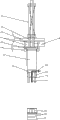
Fig. 1 is the structural representation of integrated punch device one embodiment of the utility model multistation;
Fig. 2 is the structural representation of smoothing mill structure shown in Figure 1;
Fig. 3 A is the structural representation that the clamp assemblies of lower cavity die mechanism shown in Figure 2 unclamps;
Fig. 3 B is the end view of Fig. 3 A;
Fig. 3 C is the structural representation that the clamp assemblies of lower cavity die shown in Figure 2 clamps;
Fig. 3 D is the end view of Fig. 3 C;
Fig. 4 is the last punch structure and the contacted structural representation of lower cavity die structure of smoothing mill structure shown in Figure 2;
Fig. 5 A is the structural representation of manipulator shown in Figure 1;
Fig. 5 B is the end view of Fig. 5 A;
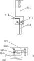
Fig. 6 A is the structural representation of the explosion-proof groove mechanism of pressure shown in Figure 1;
Fig. 6 B is the end view of Fig. 6 A.
Embodiment
As shown in Figure 1, in an embodiment of the integrated punch device of multistation of the present utility model, it is used for the processing mobile phone battery case, the integrated punch device of this multistation comprises punch press workbench and the bracing frame that is provided with on the described punch press workbench, wherein, on the punch press workbench conveyer belt is installed, by manipulator the battery of mobile phone shell to be processed on the conveyer belt is transported to each processing mold, deliver to next operation again after finishing corresponding working procedures, and punch die 111 is installed on bracing frame, particularly, punch die 111 is installed on the cope match-plate pattern 119 of bracing frame, this punch die 111 can move along the direction perpendicular to the punch press workbench, and processing mold is connected with punch die 111, moves both vertically with realization, at work, 111 pairs of processing mold application of forces of punch die, so that processing mold flexible in vertical direction, the elastomeric element that wherein has can be a spring, glue or cylinder etc.; At formative stage, after by compound blanking die raw material being finished initial work earlier, sent conveyer belt, then carry out oval mould molding assembly, finish big ellipse respectively, the moulding of middle ellipse and little ellipse, then oval-shaped formed body is processed into cuboid by commentaries on classics side's mould, then the formed body of rectangle is transported to the finish draw mould by conveyer belt again, carry out stretched operation by the finish draw mould, for example draw the aluminium operation, the formed body of rectangle is processed into the rectangle battery of mobile phone shell of openings at one side, this moment rectangle battery of mobile phone shell the opening part out-of-flatness, therefore inventive point of the present utility model is, is integrated with to be used for smoothing mill structure that the battery case opening part is cut edge, this smoothing mill structure receives the battery of mobile phone shell after finish draw Mould Machining, its essence is cut to the battery of mobile phone shell of the smooth and compound standard of opening.
As shown in Figure 1; this smoothing mill structure comprises epirelief mold mechanism 11 and lower cavity die mechanism 12; wherein; epirelief mold mechanism 11 is arranged on the bracing frame, and can be along moving perpendicular to punch press workbench direction, to realize descend back and lower cavity die cooperating under the drive of punch die 111; be separated with lower cavity die after rising; lower cavity die mechanism 12 is arranged on the punch press workbench, and the end of next-door neighbour's conveyer belt, to finish receiving the battery of mobile phone shell behind the finish draw.As shown in Figure 2, punch die 111 is connected with epirelief mold mechanism 11 by four push rods 112.In specific design; but epirelief mold mechanism 11 comprises the cutting knife installation portion that cutting knife and along continuous straight runs move; cutting knife is arranged on the cutting knife installation portion; this cutting knife installation portion comprises horizontal slide and installation component; wherein; horizontal slide is connected with four push rods 112; and installation component is arranged on the bottom of horizontal slide; as shown in Figure 2; horizontal slide comprises the upper padding plate 113 of horizontal positioned from top to bottom successively; be arranged on upper padding plate 113 bottoms and vertically place four slide rails 114; between four slide rails 114, be provided with inner slide 115, to realize that horizontal direction moves, in force; this inner slide 115 can slide on horizontal any direction; in a preferred embodiment, this inner slide 115 can all around move on the four direction in the horizontal direction; and installation component is connected with the bottom of inner slide 115; thereby under the drive of inner slide 115, carry out the motion of horizontal direction, be provided with four slide rail pressing plates 116 in addition in the bottom of four slide rails 114, to reinforce four slide rails 114.As shown in Figure 2, installation component mainly comprises superposed connecting plate 117, be arranged on the upper die plate 118 of connecting plate 117 bottoms, and the upper mould fixed plate 1111 that is arranged on upper die plate 118 bottoms, in specific design, cutting knife is installed on the upper die plate 118, the gas hole of perforation is set on cutting knife 1113, the direction of this gas hole is perpendicular to the punch press workbench, in a preferred embodiment, " " " type structure imports from the upper level end at its airflow direction this cutting knife 1113, and derives from the lower vertical direction; the horizontal end at this cutting knife 1113 is provided with gas-tpe fitting 1110, to import extraneous gas in order to fall.When concrete work, the mobile realization of cutting knife 1113 is carried out flat cut to the opening of battery of mobile phone shell, and the gas hole on the cutting knife 1113 realizes that the battery of mobile phone shell that is positioned at lower cavity die mechanism 12 was carried out for two stages blows, wherein, it is after carrying the battery of mobile phone shell of coming to blow to certain position on manipulator 2 that phase I blows, again by the clamp assemblies 121 of lower cavity die mechanism with its clamping, after flat cut is finished, carry out second stage and blow, the battery of mobile phone shell that machines is blown out from discharging opening 4; When specific design, discharging opening 4 be arranged on clamp assemblies 121 below, and between clamp assemblies 121 and discharging opening 4, be provided with location-plate 3, this location-plate 3 can move horizontally, and realizing and will close or open discharging opening, makes when blowing in the phase I, the battery of mobile phone shell for the treatment of flat cut is positioned on this location-plate 3, and when second stage was blown, this location-plate 3 sliped off, and realized the battery of mobile phone shell is blown out from discharging opening.During specific design, location-plate 3 is provided with slide block, and the punch press workbench is provided with the chute that matches with slide block, and location-plate 3 is connected with the punch press workbench with chute by this slide block, to realize horizontal slip.Clamping for 121 pairs of battery of mobile phone shells of clamp assemblies; can drop to after lower cavity die mechanism 12 contacts by epirelief mold mechanism 11; by epirelief mold mechanism 11 these clamp assemblies 121 of extruding; realization to the driving of clamp assemblies 121 to clamp the battery of mobile phone shell; after epirelief mold mechanism 11 is separated with lower cavity die mechanism 12, clamp assemblies 121 will unclamp the clamping to the battery of mobile phone shell.
As shown in Figure 2, lower cavity die mechanism 12 mainly comprises the clamp assemblies 121 that is positioned at the bottom, the double-deck lower bolster 122 that is arranged on clamp assemblies 121 bottoms, and the base plate 123 that is arranged on double-deck lower bolster 122 bottoms; For the battery of mobile phone shell is clamped, this clamp assemblies 121 comprises four slide blocks, and the guide rail that matches with four slide blocks respectively, thereby contacts with four sides of battery of mobile phone shell respectively at four direction, to clamp this battery of mobile phone shell securely.In the preferred embodiment shown in Fig. 3 A~3D, this clamp assemblies 121 comprises 1211,1212 and two driven sliding block 1213,1214 of two active sliding block, wherein, each slide block correspondence is provided with a guide rail, the guide rail that matches with active sliding block has downward-sloping to be used for the inclined-plane of this active sliding block 1211,1212 guiding to lower slider, in this embodiment, the angle of inclination on this inclined-plane is 20 degree, and the contact-making surface of the guide rail that active sliding block 1211,1212 matches with it and the inclined-plane of this guide rail are complementary; When this clamp assemblies 121 is in the state that unclamps shown in Fig. 3 A and 3B, two active sliding block 1211,1212 top is higher than the top of two driven sliding block, two active sliding block 1211,1212 are separately positioned on two driven sliding block 1213,1214 both sides, and two active sliding block 1211,1212 all with two driven sliding block 1213,1214 contact, two driven sliding block 1213,1214 have and are inclined upwardly with by two active sliding block 1211, the inclined-plane of slide in opposition is carried out in 1212 driving, active sliding block 1211,1212 with driven sliding block 1213,1214 the contact-making surface and the inclined-plane of driven sliding block are complementary.At work, external force is executed vertical force to the top of two active sliding block simultaneously, because the contact-making surface of the guide rail that active sliding block matches with it is the inclined-plane, thereby make active sliding block glide along the inclined-plane, be that active sliding block not only moves downward, also slide towards direction near the battery of mobile phone shell, the contact-making surface of active sliding block and driven sliding block also is the inclined-plane simultaneously, thereby make driven sliding block under the effect of the active sliding block application of force, also slide towards direction near the battery of mobile phone shell, draw in thereby make two active sliding block and two driven sliding block be, promptly shown in Fig. 3 C and 3D towards the direction of battery of mobile phone shell.In this embodiment, this clamp assemblies 121 and device synchronization, be according to the operation of equipment design, being equipment operation clamps the battery of mobile phone shell or unclamps to formulating direction that the position just begins to design, thereby can carry out the round periodic duty that matches with equipment the time in accordance with regulations.From the conveying effect at manipulator is not can finish the work as usual under the very accurate situation yet.Outward appearance to product can not cause bad collision, avoids the processing of product defective; By the clamping of 121 pairs of battery of mobile phone shells of this clamp assemblies, when cutting edge, otch can be on same plane, and high conformity can not cause the mutual shovel of the punch edge of a knife and the lower cavity die edge of a knife to cut.Shown in Fig. 2 and 4; for two active sliding block of giving clamp assemblies 121 apply external force; bottom at the upper die plate of epirelief mold mechanism 11 is provided with the drive post assembly; thereby drop to the position of lower cavity die mechanism 12 at epirelief mold mechanism 11; this drive post assembly can be to compressing the top of two active sliding block; make two active sliding block move downward; in a preferred embodiment; this drive post assembly comprises four drive post 1112; wherein; two drive post assemblies compress an active sliding block, and two other drive post assembly compresses another active sliding block.In this embodiment, when epirelief mold mechanism 11 rigidly connected two active sliding block that touch down die, four drive post 1112 compressed two active sliding block and move downward the end of to, thereby clamp assemblies 121 packs tightly product, begins to go on slide rail simultaneously, began to cut edge.Punch die 111 is gone to bottom dead centre, and last slide rail is covered, and finish the battery of mobile phone shell and cut edge, the slide block bottom out of punch die 111, last punch slide rail is owing to the effect of upper spring power begins to walk downwards.
Shown in Fig. 1,5A and 5B; the punch press workbench is provided with the manipulator 2 that is used for clamping side cut waste material; this manipulator has two positions; wherein; a position is positioned at above the clamp assemblies 121, and in the time of above being positioned at clamp assemblies 121, this manipulator just can carry out clamping to the side cut waste material; another position is for leaving clamp assemblies 121, and epirelief mold mechanism 11 and lower cavity die mechanism 12 just can cooperatively interact and cut edge this moment.In this embodiment, this manipulator 2 comprises two arms, each arm correspondence is provided with a mechanical hand lever 24, each arm comprises two guide pillars 23 that are slidingly connected on the mechanical hand lever 24, be arranged on the guide pillar pressing plate 25 of two guide pillar 23 bottoms, be arranged on two material folding connecting plates 26 between the guide pillar, material folding connecting plate 26 is provided with and the suitable draw-in groove of battery of mobile phone outer casing thickness, on guide pillar 23, be provided with cylinder 21 and air cylinder fixed plate 22, at work, two arms are by the draw-in groove on the material folding connecting plate separately, the both sides of the cutting waste material of battery of mobile phone shell are blocked, thereby this waste material is pressed from both sides away, thereby realize that the oral area waste material that will cut edge moves to assigned address, and when removing waste material, can friction not arranged with lower cavity die.
Shown in Fig. 1,6A and 6B; the integrated punch device of this multistation also is integrated with the explosion-proof groove mechanism of pressure that is used for the battery case side is processed explosion-proof groove; thereby the battery of mobile phone shell is being carried out before essence cuts; process explosion-proof groove earlier; shown in Fig. 6 A and 6B, this is pressed explosion-proof groove mechanism to comprise to be arranged on the bracing frame and can and be arranged on dip mold mechanism 52 on the punch press workbench along the top die mechanism 51 that moves perpendicular to punch press workbench direction.This top die mechanism 51 comprises the patrix connecting plate 511 that is arranged on top, the upper mould fixed plate 512 that is arranged on patrix connecting plate 511 bottoms, and the last punch 513 that is arranged on upper mould fixed plate 512 bottoms, and is provided with
 The
The gas hole 514 of type, it runs through upper mould fixed plate 512 and last punch 513, and dip mold mechanism 52 mainly comprises lower cavity die 521, guide pillar 522, counterdie fixed head 523, lower bolster 524, guide plate 525, push rod 527, explosion-proof punch 526, moving oblique contract slide block 528 and oblique contract 529; At work, top die mechanism toward pressing down, reaches desired location with the battery of mobile phone shell, and as the last punch of pressing explosion-proof top die mechanism, the gas hole on this in punch plays the discharging effect after having pressed explosion-proof line.When the endoporus of the locating piece of dip mold mechanism inserts at last punch, play the role of positioning, the explosion-proof work of pressing is finished in moving oblique contract slide block horizontal movement, and tiltedly contract plays a driving role.
The utility model describes by several specific embodiments, it will be appreciated by those skilled in the art that under the situation that does not break away from the utility model scope, can also carry out various conversion and be equal to alternative the utility model.In addition, at particular condition or concrete condition, can make various modifications to the utility model, and not break away from scope of the present utility model.Therefore, the utility model is not limited to disclosed specific embodiment, and should comprise the whole execution modes that fall in the utility model claim scope.
Claims (8)
1, the integrated punch device of a kind of multistation, be used for the processing mobile phone battery case, the integrated punch device of described multistation comprises punch press workbench and the bracing frame that is provided with on the described punch press workbench, it is characterized in that, the integrated punch device of described multistation is integrated with and is used for smoothing mill structure that the battery case opening part is cut edge, and described smoothing mill structure comprises and is arranged on the support frame as described above and can and be arranged on lower cavity die mechanism on the described punch press workbench along the epirelief mold mechanism that moves perpendicular to described punch press workbench direction; Wherein, but described epirelief mold mechanism comprises the cutting knife installation portion that cutting knife and along continuous straight runs move, and described cutting knife is arranged on the described cutting knife installation portion, and gas hole is set on cutting knife, and the direction of described gas hole is perpendicular to described punch press workbench; Described lower cavity die mechanism comprises the clamp assemblies that is used to clamp or unclamp battery case, is provided with discharging opening below described clamp assemblies, is provided with the location-plate that is used to place battery case that can move horizontally between described clamp assemblies and discharging opening.
2, the integrated punch device of multistation according to claim 1, it is characterized in that, described punch press workbench is provided with the manipulator that is used for clamping side cut waste material, described manipulator has two positions, wherein, a position is positioned at above the described clamp assemblies, and another position is for leaving described clamp assemblies.
3, the integrated punch device of multistation according to claim 1 and 2 is characterized in that, described clamp assemblies comprises four slide blocks, and respectively with described four guide rails that slide block matches.
4, the integrated punch device of multistation according to claim 3, it is characterized in that, described clamp assemblies comprises two active sliding block and two driven sliding block, wherein, each slide block correspondence is provided with a guide rail, the guide rail that matches with active sliding block has downward-sloping being used for this active sliding block guiding to the inclined-plane of lower slider, and the contact-making surface of the guide rail that active sliding block matches with it and the inclined-plane of this guide rail are complementary; Described two active sliding block are separately positioned on the both sides of described two driven sliding block, described two driven sliding block have and are inclined upwardly to carry out the inclined-plane of slide in opposition by the driving of described two active sliding block, and the contact-making surface of active sliding block and driven sliding block and the inclined-plane of driven sliding block are complementary.
5, the integrated punch device of multistation according to claim 4 is characterized in that, the cutting knife installation portion is provided with the drive post assembly that is used to compress described two active sliding block.
6, the integrated punch device of multistation according to claim 5 is characterized in that, described drive post assembly comprises four drive post, and wherein, two drive post compress an active sliding block, and other two drive post compress another active sliding block.
7, the integrated punch device of multistation according to claim 1 and 2, it is characterized in that, described location-plate is provided with slide block, and described punch press workbench is provided with the chute that matches with described slide block, and described location-plate is connected with described punch press workbench with chute by described slide block.
8, the integrated punch device of multistation according to claim 1 and 2 is characterized in that, the integrated punch device of described multistation also is integrated with the explosion-proof groove mechanism of pressure that is used for the battery case side is processed explosion-proof groove; The explosion-proof groove mechanism of described pressure comprises and is arranged on the support frame as described above and can and be arranged on dip mold mechanism on the described punch press workbench along the top die mechanism that moves perpendicular to described punch press workbench direction.
Priority Applications (1)
| Application Number | Priority Date | Filing Date | Title |
|---|---|---|---|
| CN200920130919U CN201392853Y (en) | 2009-04-23 | 2009-04-23 | Multi-position integral punching press device |
Applications Claiming Priority (1)
| Application Number | Priority Date | Filing Date | Title |
|---|---|---|---|
| CN200920130919U CN201392853Y (en) | 2009-04-23 | 2009-04-23 | Multi-position integral punching press device |
Publications (1)
| Publication Number | Publication Date |
|---|---|
| CN201392853Y true CN201392853Y (en) | 2010-01-27 |
Family
ID=41599674
Family Applications (1)
| Application Number | Title | Priority Date | Filing Date |
|---|---|---|---|
| CN200920130919U Expired - Fee Related CN201392853Y (en) | 2009-04-23 | 2009-04-23 | Multi-position integral punching press device |
Country Status (1)
| Country | Link |
|---|---|
| CN (1) | CN201392853Y (en) |
Cited By (11)
| Publication number | Priority date | Publication date | Assignee | Title |
|---|---|---|---|---|
| CN101912914A (en) * | 2010-08-02 | 2010-12-15 | 山东神工宏全模具有限公司 | Full-automatic multistation notching machine |
| CN102244208A (en) * | 2011-05-30 | 2011-11-16 | 梅承寨 | Manufacturing method and equipment of metal battery shell |
| CN102248062A (en) * | 2011-06-17 | 2011-11-23 | 苏州旭创精密模具有限公司 | Die for trimming casing of MP3 |
| CN103331368A (en) * | 2013-07-25 | 2013-10-02 | 新疆帅府高新技术有限公司 | Straightly-arranged multi-station punching machine |
| CN104701574A (en) * | 2015-02-11 | 2015-06-10 | 东莞市骏泰精密机械有限公司 | Molding mechanism for arc-shaped battery cell of flexible packaging lithium battery |
| CN106738706A (en) * | 2016-12-06 | 2017-05-31 | 江苏精研科技股份有限公司 | Automatic cutting system and punching flow |
| CN107377729A (en) * | 2017-07-25 | 2017-11-24 | 深圳市科达利实业股份有限公司 | A kind of method for drawing and setup for drawing parts |
| CN108465738A (en) * | 2018-05-29 | 2018-08-31 | 苏州宝成汽车冲压有限公司 | Fuel injection system continuous mould blank is molded synchronizing device |
| CN109013864A (en) * | 2018-09-14 | 2018-12-18 | 河南均美铝业有限公司 | A kind of aluminium alloy stamping modular mold |
| CN110253297A (en) * | 2019-07-04 | 2019-09-20 | 佛山市精达信五金电器有限公司 | Compressor base frame punching tapping production line |
| CN116786674A (en) * | 2023-08-25 | 2023-09-22 | 常州松田伺服冲床有限公司 | Full-automatic battery box stretching punch press and battery box stretching method |
-
2009
- 2009-04-23 CN CN200920130919U patent/CN201392853Y/en not_active Expired - Fee Related
Cited By (11)
| Publication number | Priority date | Publication date | Assignee | Title |
|---|---|---|---|---|
| CN101912914A (en) * | 2010-08-02 | 2010-12-15 | 山东神工宏全模具有限公司 | Full-automatic multistation notching machine |
| CN102244208A (en) * | 2011-05-30 | 2011-11-16 | 梅承寨 | Manufacturing method and equipment of metal battery shell |
| CN102248062A (en) * | 2011-06-17 | 2011-11-23 | 苏州旭创精密模具有限公司 | Die for trimming casing of MP3 |
| CN103331368A (en) * | 2013-07-25 | 2013-10-02 | 新疆帅府高新技术有限公司 | Straightly-arranged multi-station punching machine |
| CN104701574A (en) * | 2015-02-11 | 2015-06-10 | 东莞市骏泰精密机械有限公司 | Molding mechanism for arc-shaped battery cell of flexible packaging lithium battery |
| CN106738706A (en) * | 2016-12-06 | 2017-05-31 | 江苏精研科技股份有限公司 | Automatic cutting system and punching flow |
| CN107377729A (en) * | 2017-07-25 | 2017-11-24 | 深圳市科达利实业股份有限公司 | A kind of method for drawing and setup for drawing parts |
| CN108465738A (en) * | 2018-05-29 | 2018-08-31 | 苏州宝成汽车冲压有限公司 | Fuel injection system continuous mould blank is molded synchronizing device |
| CN109013864A (en) * | 2018-09-14 | 2018-12-18 | 河南均美铝业有限公司 | A kind of aluminium alloy stamping modular mold |
| CN110253297A (en) * | 2019-07-04 | 2019-09-20 | 佛山市精达信五金电器有限公司 | Compressor base frame punching tapping production line |
| CN116786674A (en) * | 2023-08-25 | 2023-09-22 | 常州松田伺服冲床有限公司 | Full-automatic battery box stretching punch press and battery box stretching method |
Similar Documents
| Publication | Publication Date | Title |
|---|---|---|
| CN201392853Y (en) | Multi-position integral punching press device | |
| CN102139312B (en) | Progressive continuous stamping die used for processing small elastic sheets | |
| CN109500242B (en) | Stamping die for molding and processing multiple surfaces of automobile skylight guide rail and stamping method thereof | |
| CN216263179U (en) | A all-in-one that cuts of bending for chip pin | |
| CN109013860A (en) | It is a kind of for processing the automatic press system of plate nut | |
| CN109248963A (en) | A kind of transmitting drawing die trimming structure of power battery shell | |
| CN203944711U (en) | The multistation machine of aerosol two piece can | |
| CN202498134U (en) | Side hole bidirectional punching die | |
| CN218593444U (en) | Secondary demolding mold | |
| CN102233372A (en) | Battery steel shell forming machine and steel shell forming method using same | |
| CN218224412U (en) | Full-automatic blanking and punching die | |
| CN206613915U (en) | The progressive die with side punching | |
| CN215997856U (en) | Scrap removing device for punching machine | |
| CN205926834U (en) | Stamping die | |
| CN214290413U (en) | Cover cup forming die with sectional type buffering piston goes out lid | |
| CN211276146U (en) | Backrest side plate forming die | |
| CN209379757U (en) | A kind of transmitting drawing die trimming structure of power battery shell | |
| CN212072736U (en) | Filter screen production mould capable of automatically cutting off excess materials | |
| CN209061958U (en) | Die drawn part rotary cutting apparatus | |
| CN111842650A (en) | Mould capable of reducing part crushing damage | |
| CN206997463U (en) | Gusset fine blanking die | |
| CN216860568U (en) | Full-automatic setting machine | |
| CN207271918U (en) | A kind of shelves shift fork planar member fine blanking die | |
| CN110899496A (en) | Backrest side plate forming die and method | |
| CN203956491U (en) | A kind of electronic household framework forming machine |
Legal Events
| Date | Code | Title | Description |
|---|---|---|---|
| C14 | Grant of patent or utility model | ||
| GR01 | Patent grant | ||
| C17 | Cessation of patent right | ||
| CF01 | Termination of patent right due to non-payment of annual fee |
Granted publication date: 20100127 Termination date: 20120423 |