CN201315744Y - Fertilizer discharging clutch device of sowing machine seed manuring box - Google Patents
Fertilizer discharging clutch device of sowing machine seed manuring box Download PDFInfo
- Publication number
- CN201315744Y CN201315744Y CNU2008200913838U CN200820091383U CN201315744Y CN 201315744 Y CN201315744 Y CN 201315744Y CN U2008200913838 U CNU2008200913838 U CN U2008200913838U CN 200820091383 U CN200820091383 U CN 200820091383U CN 201315744 Y CN201315744 Y CN 201315744Y
- Authority
- CN
- China
- Prior art keywords
- sliding sleeve
- fertilizer
- fertilizer discharging
- clutch
- fork
- Prior art date
- Legal status (The legal status is an assumption and is not a legal conclusion. Google has not performed a legal analysis and makes no representation as to the accuracy of the status listed.)
- Expired - Fee Related
Links
Images
Abstract
A fertilizer discharging clutch device of a sowing machine seed manuring box belongs to agricultural machinery. A fertilizer discharging chain wheel provided with an active jaw on the inner side end surface thereof is rotationally sleeved at the outer side part of a fertilizer discharging shaft; a sliding sleeve provided with a passive jaw on the end surface thereof is assembled on the fertilizer discharging shaft in a manner that the sliding sleeve is positioned in radial and circumferential directions and movable in axial direction; the active and the passive jaws are combined with each other or separated to be matched with each other; a fixing plate is fixedly assembled on a fertilizer discharging box body; a clutch fork is movably assembled on the fixing plate and matched with the sliding sleeve in a fork lifting manner; a tightening wire is connected at the side part of the clutch fork; and a spring is sleeved on a feed shaft and is positioned between the fixing plate and the sliding sleeve. The utility model has the advantages of simple structure, small size, light weight, long service life, convenient use, good clutching performance, reliable operation and few errors.
Description
Technical field
The utility model belongs to agricultural machinery, relates generally to the fertilizer control device on the seeding machinary.
Background technology
At present, the fertilizer operation rotational power of sower fertilizer expelling shaft all rotates from the facility land wheel and finishes by the fertilizer transmission system transmission that chain, sprocket wheel constitute, owing in the fertilizer power drive system, power-off device is not set, fertilizer apparatus still continues fertilizer when making the sower operation to the edge of a field, can't stop, cause the loss and waste of chemical fertilizer, improved agriculture production cost.In recent years,, partly begin equipped fertilizer arrangement of clutch on the seeding machinary for solving foregoing problems, but because the defective on the structural design, its operational reliability, operation convenience, use flexibility aspect still need be improved and be improved.
Summary of the invention
The purpose of this utility model is exactly the problem that exists at above-mentioned prior art, and design provides a kind of sower seed manure case fertilizer arrangement of clutch of new construction, reaches that clutch is effective, operation simple and convenient, the reliable purpose of operation.
Basic design of the present utility model is, sower seed manure case fertilizer arrangement of clutch comprises seed manure casing, fertilizer expelling shaft, seed manure case side plate, bearing block, row fat sprocket and bearing, is sleeved on rotationally on the fertilizer expelling shaft outside portion at the row fat sprocket that is provided with the active jaw tooth on the inboard end face; The sliding sleeve that end face is provided with passive tooth inserted tooth radially, circumferentially the location, axially movably be fitted on the fertilizer expelling shaft, its passive tooth inserted tooth mutually combines with the active jaw tooth or separates cooperation; Admittedly join fixed head on the fertilizer casing, the clutch fork is fitted on the fixed head movably, and clutch fork and the assembling of sliding sleeve fork are closed, and backguy is connected on the clutch fork sidepiece; Spring housing fits on the fertilizer expelling shaft, and between fixed head and sliding sleeve, spring both sides end face contacts cooperation with fixed head respectively with sliding sleeve.
The utility model adopts sliding sleeve, tooth embedding, the box-like fertilizer clutch structure of stay wire groups, have simple in structure, volume is little, in light weight, long service life, easy to operate, clutch is effective, operation is reliable, fault is few characteristics, can be fitted on the various seeding machinaries and use, applied widely.
Description of drawings
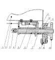
Accompanying drawing is a sower seed manure case fertilizer arrangement of clutch overall arrangement structural representation.
Piece number explanation among the figure:
1, seed manure casing, 2, backguy, 3, fertilizer expelling shaft, 4, fixed head, 5, clutch fork, 6, spring, 7, sliding sleeve, 8, seed manure case side plate, 9, bearing block, 10, row fat sprocket, 11, bearing, 12, active jaw tooth, 13, passive tooth inserted tooth.
Embodiment
Below in conjunction with accompanying drawing the utility model optimum implementation is described in detail.Sower seed manure case fertilizer arrangement of clutch comprises seed manure casing 1, fertilizer expelling shaft 3, seed manure case side plate 8, bearing block 9, row fat sprocket 10 and bearing 11, is sleeved on rotationally on fertilizer expelling shaft 3 outside portions at the row fat sprocket 10 that is provided with active jaw tooth 12 on the inboard end face; The sliding sleeve 7 that end face is provided with passive tooth inserted tooth 13 radially, circumferentially the location, axially movably be fitted on the fertilizer expelling shaft 3, its passive tooth inserted tooth 13 mutually combines with active jaw tooth 12 or separates cooperation; Admittedly join fixed head 4 on fertilizer casing 1, clutch fork 5 is fitted on the fixed head 4 movably, and clutch fork 5 closes with sliding sleeve 7 fork assemblings, and backguy 2 is connected clutch and pitches on 5 sidepieces; Spring 6 covers fit on the fertilizer expelling shaft 3, and between fixed head 4 and sliding sleeve 7, spring 7 both sides end faces contact cooperation with fixed head 4 with sliding sleeve 7 respectively.
During operation, the sower land wheel rotates, by chain rotary power is passed on the row fat sprocket 10, row fat sprocket 10 is rotated on fertilizer expelling shaft 3, at spring 6 sliding sleeve 7 is passed laterally, when passive tooth inserted tooth 13 was combined with active jaw tooth 12, sliding sleeve 7 drove fertilizer expelling shaft 3 and rotates in the lump, realizes and finish the fertilizer operation; Pulling backguy 2 is moved clutch fork 5 on fixed head 4, clutch fork 5 drives sliding sleeves 7 and moves on fertilizer expelling shaft 3, and passive tooth inserted tooth 13 is broken away from and the combining of active jaw tooth 12, fertilizer expelling shaft 3 stops operating, facility stop the fertilizer operation, and at this moment, row fat sprocket 10 dallies on fertilizer expelling shaft 3.
Claims (1)
1, a kind of sower seed manure case fertilizer arrangement of clutch, comprise seed manure casing (1), fertilizer expelling shaft (3), seed manure case side plate (8), bearing block (9), row fat sprocket (10) and bearing (11), it is characterized in that being sleeved on rotationally on fertilizer expelling shaft (3) outside portion at the row fat sprocket (10) that is provided with active jaw tooth (12) on the inboard end face; The sliding sleeve (7) that end face is provided with passive tooth inserted tooth (13) radially, circumferentially the location, axially movably be fitted on the fertilizer expelling shaft (3), its passive tooth inserted tooth (13) mutually combines with active jaw tooth (12) or separates cooperation; Admittedly join fixed head (4) on fertilizer casing (1), clutch fork (5) is fitted on the fixed head (4) movably, and clutch fork (5) closes with the assembling of sliding sleeve (7) fork, and backguy (2) is connected on clutch fork (5) sidepiece; Spring (6) cover fits on the fertilizer expelling shaft (3), is positioned between fixed head (4) and the sliding sleeve (7), and spring (7) both sides end face contacts cooperation with fixed head (4) with sliding sleeve (7) respectively.
Priority Applications (1)
| Application Number | Priority Date | Filing Date | Title |
|---|---|---|---|
| CNU2008200913838U CN201315744Y (en) | 2008-11-19 | 2008-11-19 | Fertilizer discharging clutch device of sowing machine seed manuring box |
Applications Claiming Priority (1)
| Application Number | Priority Date | Filing Date | Title |
|---|---|---|---|
| CNU2008200913838U CN201315744Y (en) | 2008-11-19 | 2008-11-19 | Fertilizer discharging clutch device of sowing machine seed manuring box |
Publications (1)
| Publication Number | Publication Date |
|---|---|
| CN201315744Y true CN201315744Y (en) | 2009-09-30 |
Family
ID=41194521
Family Applications (1)
| Application Number | Title | Priority Date | Filing Date |
|---|---|---|---|
| CNU2008200913838U Expired - Fee Related CN201315744Y (en) | 2008-11-19 | 2008-11-19 | Fertilizer discharging clutch device of sowing machine seed manuring box |
Country Status (1)
| Country | Link |
|---|---|
| CN (1) | CN201315744Y (en) |
Cited By (5)
| Publication number | Priority date | Publication date | Assignee | Title |
|---|---|---|---|---|
| CN103460870A (en) * | 2013-09-23 | 2013-12-25 | 永昌县恒源农机制造有限公司 | Separation and reunion operating control device of seeding and fertilizer distributing machine |
| CN105156488A (en) * | 2015-09-28 | 2015-12-16 | 金湖小青青机电设备有限公司 | Mechanical clutch transmission device for combined seed and fertilizer drill |
| CN105009764B (en) * | 2014-04-17 | 2017-09-12 | 株式会社久保田 | It is equipped on the fertilizer apparatus of traveling car body |
| CN107318317A (en) * | 2017-08-18 | 2017-11-07 | 甘肃洮河拖拉机制造有限公司 | Trench digging shaping plastic film mulch rape film side seeder |
| CN109287213A (en) * | 2017-07-25 | 2019-02-01 | 乌兰浩特市顺源农牧机械制造有限公司 | A kind of agricultural seeding machine feed mechanism for seed arrangement of clutch |
-
2008
- 2008-11-19 CN CNU2008200913838U patent/CN201315744Y/en not_active Expired - Fee Related
Cited By (6)
| Publication number | Priority date | Publication date | Assignee | Title |
|---|---|---|---|---|
| CN103460870A (en) * | 2013-09-23 | 2013-12-25 | 永昌县恒源农机制造有限公司 | Separation and reunion operating control device of seeding and fertilizer distributing machine |
| CN105009764B (en) * | 2014-04-17 | 2017-09-12 | 株式会社久保田 | It is equipped on the fertilizer apparatus of traveling car body |
| CN105156488A (en) * | 2015-09-28 | 2015-12-16 | 金湖小青青机电设备有限公司 | Mechanical clutch transmission device for combined seed and fertilizer drill |
| CN109287213A (en) * | 2017-07-25 | 2019-02-01 | 乌兰浩特市顺源农牧机械制造有限公司 | A kind of agricultural seeding machine feed mechanism for seed arrangement of clutch |
| CN109287213B (en) * | 2017-07-25 | 2024-02-09 | 乌兰浩特市顺源农牧机械制造有限公司 | Seed metering device clutch device of agricultural seeder |
| CN107318317A (en) * | 2017-08-18 | 2017-11-07 | 甘肃洮河拖拉机制造有限公司 | Trench digging shaping plastic film mulch rape film side seeder |
Similar Documents
| Publication | Publication Date | Title |
|---|---|---|
| CN201315744Y (en) | Fertilizer discharging clutch device of sowing machine seed manuring box | |
| RU2015119479A (en) | PNEUMATIC SEED DISPENSER WITH INTERNAL DRIVE | |
| CN2917224Y (en) | Activation power clutch device of precision seeder fertilizing axis | |
| CN101524017A (en) | Inter-plant weeding spring-tooth flexible shaft driving mechanism of paddy field weeding machine | |
| CN201919321U (en) | Mechanical precise dibbling device | |
| CN201585243U (en) | Combined upright comb type crop seeding-strip soil-loosening and weeding mechanism | |
| CN201182062Y (en) | Cover belt type tilling-sowing machine with centrifugal clutch | |
| CA2482218A1 (en) | Power transmission mechanism | |
| CN201612025U (en) | Air-suction precision seeder gearbox | |
| CN202768750U (en) | Speed changing box steering mechanism | |
| CN203353108U (en) | Combined variable speed seed metering device | |
| CN210537281U (en) | Transmission device of automatic rotary cultivator | |
| CN209257769U (en) | Has one-way driving mechanism configuration in the wheel hub structure of reverse position | |
| CN201025777Y (en) | Fertilizer discharging shaft driving dynamic engaging and disengaging device of accurate seeding machine | |
| CN106900292A (en) | Steel rider and dial-type machine for forming cylindrical bale | |
| CN201029288Y (en) | Paddy field precision fertilizing driving mechanism | |
| EP1621067A3 (en) | Rotary rake for a haymaking machine | |
| CN220268259U (en) | One-way clutch of seeder | |
| CN205978173U (en) | Agricultural machine engine electromagnetic clutch | |
| CN106945514B (en) | Self-walking type rice steering mechanism of transplanting machine | |
| CN110043612A (en) | High-speed rice seedling planter Multifunctional combination transmission case | |
| CN202364541U (en) | Through-shaft-end transmission type slurry-stirring land leveler | |
| CN201011769Y (en) | Engaging and disengaging gear of the sowing implement | |
| CN201246427Y (en) | Unilateral transmission clutch | |
| CN205639520U (en) | Circle bale bundling machine's two side synchronous drive device of feeding fork |
Legal Events
| Date | Code | Title | Description |
|---|---|---|---|
| C14 | Grant of patent or utility model | ||
| GR01 | Patent grant | ||
| C17 | Cessation of patent right | ||
| CF01 | Termination of patent right due to non-payment of annual fee |
Granted publication date: 20090930 Termination date: 20111119 |