CN201016966Y - Manual scanner for spiral weld joint - Google Patents
Manual scanner for spiral weld joint Download PDFInfo
- Publication number
- CN201016966Y CN201016966Y CNU2007201036862U CN200720103686U CN201016966Y CN 201016966 Y CN201016966 Y CN 201016966Y CN U2007201036862 U CNU2007201036862 U CN U2007201036862U CN 200720103686 U CN200720103686 U CN 200720103686U CN 201016966 Y CN201016966 Y CN 201016966Y
- Authority
- CN
- China
- Prior art keywords
- probe holder
- scanning frame
- probe
- helical
- scanning
- Prior art date
- Legal status (The legal status is an assumption and is not a legal conclusion. Google has not performed a legal analysis and makes no representation as to the accuracy of the status listed.)
- Expired - Lifetime
Links
- 239000000523 sample Substances 0.000 claims abstract description 124
- 229910000831 Steel Inorganic materials 0.000 claims abstract description 19
- 239000010959 steel Substances 0.000 claims abstract description 19
- 230000007246 mechanism Effects 0.000 claims abstract description 11
- 238000005096 rolling process Methods 0.000 claims abstract description 9
- 238000005476 soldering Methods 0.000 claims description 14
- 238000002604 ultrasonography Methods 0.000 claims description 10
- 230000008878 coupling Effects 0.000 claims description 9
- 238000010168 coupling process Methods 0.000 claims description 9
- 238000005859 coupling reaction Methods 0.000 claims description 9
- RYGMFSIKBFXOCR-UHFFFAOYSA-N Copper Chemical compound [Cu] RYGMFSIKBFXOCR-UHFFFAOYSA-N 0.000 claims description 3
- 239000004411 aluminium Substances 0.000 claims description 3
- 229910052782 aluminium Inorganic materials 0.000 claims description 3
- XAGFODPZIPBFFR-UHFFFAOYSA-N aluminium Chemical compound [Al] XAGFODPZIPBFFR-UHFFFAOYSA-N 0.000 claims description 3
- 229910052802 copper Inorganic materials 0.000 claims description 3
- 239000010949 copper Substances 0.000 claims description 3
- 239000007769 metal material Substances 0.000 claims description 3
- 239000011368 organic material Substances 0.000 claims description 3
- 230000003068 static effect Effects 0.000 claims description 2
- 238000001514 detection method Methods 0.000 abstract description 19
- 238000012360 testing method Methods 0.000 abstract description 6
- 238000009428 plumbing Methods 0.000 abstract 1
- 230000002950 deficient Effects 0.000 description 10
- 238000003466 welding Methods 0.000 description 4
- 239000002184 metal Substances 0.000 description 3
- 229910052751 metal Inorganic materials 0.000 description 3
- 238000000034 method Methods 0.000 description 3
- 239000011324 bead Substances 0.000 description 2
- 238000007689 inspection Methods 0.000 description 2
- 238000009434 installation Methods 0.000 description 2
- 229910000838 Al alloy Inorganic materials 0.000 description 1
- 239000000956 alloy Substances 0.000 description 1
- 230000002146 bilateral effect Effects 0.000 description 1
- 230000007547 defect Effects 0.000 description 1
- 238000009826 distribution Methods 0.000 description 1
- 238000005516 engineering process Methods 0.000 description 1
- 238000003384 imaging method Methods 0.000 description 1
- 239000000463 material Substances 0.000 description 1
- 239000011159 matrix material Substances 0.000 description 1
- 238000005259 measurement Methods 0.000 description 1
- 230000003287 optical effect Effects 0.000 description 1
- 230000035945 sensitivity Effects 0.000 description 1
- 238000003860 storage Methods 0.000 description 1
- 238000010408 sweeping Methods 0.000 description 1
- XLYOFNOQVPJJNP-UHFFFAOYSA-N water Substances O XLYOFNOQVPJJNP-UHFFFAOYSA-N 0.000 description 1
Images


Landscapes
- Investigating Or Analyzing Materials By The Use Of Ultrasonic Waves (AREA)
Abstract
The utility model discloses a manual scanner of spiral weld that is used for phased array to combine TOFD ultrasonic detection to walk on the pipeline when labour steel pipeline spiral weld. To the field of testing and plumbing systems for equipment not otherwise provided for. The scanning device mainly comprises a scanning frame [1], a probe frame [6], rolling wheel mechanisms and an encoder mechanism, wherein the rolling wheel mechanisms are arranged at four corners of the rectangular scanning frame [1], the probe frame [6] is arranged on probe frame moving tracks [4] at two sides of the scanning frame [1], and the encoder mechanism is arranged at one side outside the scanning frame [1 ]. The scanner can stably and reliably walk on the pipeline when detecting the spiral weld of the steel pipeline in service, the position of the probe can be always accurately parallel to the surface of the weld of the pipeline and a certain distance is ensured, and the manual scanner which can reliably and accurately detect the spiral weld of the steel pipeline in service is provided for phased array combined TOFD ultrasonic detection.
Description
Technical field
The utility model is to be used for the helical soldering seam manual checking machine that phased array is walked on pipeline when using as a servant the steel pipe spiral weld in conjunction with the TOFD ultrasound examination.The test and the piping system technical field that relate to other class equipment not to be covered.
Background technology
Helical soldering seam manual checking machine is used for the mechanical hook-up that phased array is walked in the enterprising every trade of pipeline when using as a servant the steel pipe spiral weld in conjunction with the TOFD ultrasound examination, phased array probe and TOFD probe are installed in respectively on the probe holder of scanner, the centre distance of phased array probe and TOFD probe is adjustable, probe can be pressed on the metal surface, and loading and unloading are free.Scanner is installed scrambler along being parallel to the scanning of detecting a flaw of bead direction walking freely on the scanner, be used to write down the scanning distance.Spiral welded steel pipe will carry out nondestructive flaw detection examination to spiral weld before dispatching from the factory.Domesticly designed a kind of automated ultrasonic flaw detecting system that is used for the spiral welded steel pipe weld seam detection already, be used for exactly the spiral weld of the steel pipe before dispatching from the factory is carried out nondestructive flaw detection examination.Its principal feature is that checkout equipment is fixed, and the welded tube rotation obtains testing result.But for labour spiral welded steel pipe, mainly be runed for many years labour spiral welded steel pipe, for various reasons spiral weld may occur the damage or defective, so when the pipeline overhaul, must carry out nondestructive flaw detection examination to spiral weld.Up to the present, also do not have to carry out the scanner that on-the-spot spiral weld detects at spiral welded steel pipe specially.So the external vertical masonry joint of employing mostly pipe is the scanner that does not also have on-the-spot spiral weld to detect.
The utility model content
The purpose of this utility model be a kind of phased array of design in conjunction with the TOFD ultrasound examination when the labour steel pipe spiral weld on pipeline stable, the helical soldering seam manual checking machine accurately of walking.
Scanner is used to make the distance that is maintained fixed between two Probe index, and aims at all the time.The adjection of scanner is to provide probe positions information to reflectoscope, so that can produce the D relevant with position scanning or B scan image. probe positions information can be provided by stepping magnetic encoder or optical encoder or potential difference meter.
X that the TOFD method is commonly used and Y are to two kinds of checking methods.The former is called D scanning, and the latter is called B scanning.
D scanning is to be the center with the weld line, disposes a pair of longitudinal wave oblique probe in opposite directions in the weld seam both sides, makes it do parallel scan (being that X is to scanning) synchronously along the weld line direction.When there is inherent vice in weld seam,, can measures defective and defective is carried out quantitatively (depth measurement is fixed high) test according to the diffracted wave signal that the defective upper and lower end parts produces.
B scanning is to make two probe edges and the perpendicular direction scanning (Y is to scanning) of weld line.The defective that scanning detects to D will be confirmed its position in the weld seam transversal section, will scan with B and accurately measure defective upper and lower end parts position, departs from the situation of two probe spacing center lines according to upper and lower end parts and measures the defective inclined degree, infers defect kind.
Phased array requires two probes that strict pose is arranged in conjunction with the TOFD ultrasound examination, so just scanner has been proposed strict requirement.
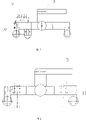
In view of this, the technical solution of the utility model such as Fig. 1, Fig. 2, shown in Figure 3, it mainly is made up of scanning frame 1, probe holder 6, scroll wheel mechanism and code device, four jiaos of rectangle scanning frame 1 are equipped with scroll wheel mechanism, probe holder 6 is installed on the probe holder moving track 4 on scanning frame 1 both sides, and code device is installed in the side outside the scanning frame 1.
Wherein scanning frame support arm 22 shapes such as Figure 19, Figure 20, shown in Figure 21, becoming scanning frame support arm 22 1 ends of " L " shape is " ∏ " shape prong that axis hole is arranged, and the other end has pan and four holes on every side thereof, and root has five holes that connect probe holder moving track 4.Probe holder moving track 4 is for there being the rectangular shaft of chute.
Probe holder 6 (is seen Figure 12, Figure 13) mainly by the fixing footstock 15 of probe holder, probe holder firm banking 17, probe holder slide rail 16, probe holder coupling link 18, probe holder depression bar 19, spring 20, unitor 21 is formed, by probe holder slide rail 16 with probe holder fixedly footstock 15 be connected with probe holder firm banking 17, unitor 21 is placed in outside the probe holder slide rail 16, and have spring 20 with probe holder fixedly footstock 15 be connected with unitor 21, probe holder fixedly footstock 15 (is seen Figure 15, Figure 16) be "T"-shaped, on the upper crosspiece both sides one hole is arranged respectively, a hole fixing spring 20 usefulness wherein, perpendicular section also has a hole.Probe holder firm banking 17 (seeing Figure 17, Figure 18) is inverse-T-shaped, and respectively there is a breach on its crosspiece both sides, and perpendicular section has two holes.Probe holder slide rail 16 shapes as shown in figure 14, for the rectangular shaft of chute is arranged.Probe holder firm banking 17 bottoms connect probe holder depression bar 19, static probe on probe holder depression bar 19 by probe holder coupling link 18.
Scroll wheel mechanism is four magnet pulleies 2 that are installed on 1 four jiaos on scanning frame, magnet pulley 2 (seeing Fig. 5, Fig. 6 Fig. 7, Fig. 8) is placed on the magnetic core wheel 12 for the non magnetic sheet of taking turns in a plurality of magnet pulley sheets interval, and two outsides of magnet pulley 2 are the magnet pulley sheet, by 2-3 root magnet pulley screw rod 13 is installed they are fixed into magnet pulley 2, a rolling bearing 14 is respectively installed at the two ends of magnetic core wheel 12, and axle passes in " ∏ " shape prong of scanning frame support arm 22 that two rolling bearings 14 are installed in 1 four jiaos on scanning frame.The non magnetic sheet of taking turns is made by non-magnet material, as metal materials such as copper, aluminium, or nonmetallic organic material.
Code device is made up of scrambler 8, scrambler moving guide rail 7, and as shown in Figure 1 and Figure 2, scrambler moving guide rail 7 is connected in the outside, one side of scanning frame 1, and scrambler 8 is installed on the scrambler moving guide rail 7.
For light, alleviate operator's burden, do not influence the normal rolling of magnet pulley 2, scanning frame 1, probe holder 6, scroll wheel mechanism and code device (magnet pulley 2 exceptions) all aluminium alloy material are made.
This scanner utilizes four magnet pulleies 2 to walk on steel pipe, makes being adsorbed on the pipeline that scanner can be firm.
Can work on multiple caliber in order to adapt to, the wheel base of scanner can change.This be because of scanning frame 1 be that a centre with two opposite side is the support body that can amount to of axle, promptly two hinge axis on a line with four scanning frame support arms 22 are that rotating shaft is amounted to, can regulate four magnet pulleies 2 according to the caliber of being checked like this, make and pop one's head in and keep in one plane, and make probe near being checked the surface, guarantee the quality of scanning.
For making the scanner can be exactly along the spiral weld scanning, probe positions is parallel with pipe welding seam surface all the time and guarantee a determining deviation, the probe of this scanner keeps probe to advance with spiral weld automatically by the slip of probe holder 6 on the probe holder moving track 4 of scanning frame 1; And probe holder adopts directed guide rail, utilizes spring 20 to compress.
This scanner has been designed the ultrasonic phase array probe scanning device with Three Degree Of Freedom, has established the position relation between this scanner and the spiral weld, has provided the position relation between phased array probe, TOFD probe and spiral pipeline weld seam and the scanner matrix.
This girth joint manual checking device is used for the mechanical hook-up that phased array is walked in the enterprising every trade of pipeline when using as a servant the steel pipe circumferential welded seam in conjunction with the TOFD ultrasound examination, phased array probe and TOFD probe are installed in respectively on the probe holder of scanner, the centre distance of phased array probe and TOFD probe is adjustable, probe can be pressed on the metal surface, and loading and unloading are free.Scanner is installed scrambler along being parallel to the scanning of detecting a flaw of bead direction walking freely on the scanner, be used to write down the scanning distance.
Therefore, this scanner is that a kind of phased array is walked stable, reliable when using as a servant the steel pipe spiral weld on pipeline in conjunction with the TOFD ultrasound examination, probe positions is all the time can be exactly parallel with the pipe welding seam surface and guarantee a determining deviation, for phased array in conjunction with the TOFD ultrasound examination provide at labour steel pipe spiral weld detect reliably, manual checking device accurately.
Description of drawings
Fig. 1 scanner constitutes front elevation
Fig. 2 scanner constitutes vertical view
Fig. 3 scanner constitutes side view
Fig. 4 scanner handle position figure
Fig. 5 magnet pulley wiring layout
Fig. 6 magnet pulley is installed screw rod shape figure
Fig. 7 magnetic core wheel shape figure
Fig. 8 rolling bearing structure figure
Fig. 9 coupling link front elevation of popping one's head in
Figure 10 coupling link side view of popping one's head in
Figure 11 depression bar shape figure that pops one's head in
Figure 12 probe holder front elevation
Figure 13 probe holder side view
Figure 14 probe holder slide rail shape figure
Figure 15 probe holder is the footstock front elevation fixedly
Figure 16 probe holder is the footstock side view fixedly
Figure 17 probe holder firm banking front elevation
Figure 18 probe holder firm banking side view
Figure 19 scanning frame support arm front elevation
Figure 20 scanning frame support arm side view
Figure 21 scanning frame support arm vertical view
Figure 22 couplant divider figure
1-scanning frame 2-magnet pulley wherein
3-set lever 4-probe holder moving track
5-probe holder slide rail 6-probe holder
7-scrambler moving guide rail 8-scrambler
9-couplant divider 10-nut
11-nut 12-magnetic core wheel
The 13-magnet pulley is installed screw rod 14-rolling bearing
The 15-probe holder is footstock 16-probe holder slide rail fixedly
17-probe holder firm banking 18-probe holder coupling link
19-probe holder depression bar 20-spring
21-unitor 22-scanning frame support arm
Embodiment
Embodiment. embodiment of the present utility model is described and the utility model is further described with this example.This example is an experimental prototype, and it constitutes as Fig. 1, Fig. 2, shown in Figure 3.This example is to utilize Ominiscan32/128PR ultrasound phase-control array 1 system to carry out the detection of in-service pipeline weld seam and mother metal is tested, in order to improve detection efficiency and defective recall rate, need one and overlap targetedly scanning equipment as auxiliary detection equipment, make seam inspection can finish the inspection of weld seam single face bilateral simultaneously, and image data is complete.
This scanner is that the Φ 720mm pipeline to Northeast China pipeline networks detects, it can not only be walked on this steel pipe, for taking into account the testing of other caliber, the minimum caliber Φ 426mm that is suitable for, the maximum caliber Φ 1016mm that is suitable for, center probe is apart from moving range 10~200mm; The maximum caliber Φ 1016mm that is suitable for; Center probe is apart from moving range 10~200mm; Its key dimension: scanning frame 1 is 405 * 325 * 38mm; Scanning frame support arm 22 is 180 * 40 * 38; Probe holder fixedly footstock 15 is height overall 23mm, the long 38mm of the high 6.5mm of crosspiece, the wide 16mm of perpendicular section; Probe holder firm banking 17 height overall 52mm; Probe holder slide rail 16 is 10 * 12 * ... mm; Magnet pulley 2 is external diameter Φ 42mm, interior external diameter Φ 20mm, thick 28mm; Nut 10 models: M5X30; Nut 11 models: M8.
Scrambler provides for R/D Tech company, the position of dynamo-electric scrambler record probe scanning.Corrective system of scrambler configuration guarantees the distance of displayed record and the position consistency of surface indicia.Record or Mk system should clearly indicate the position of defective with respect to the scanning starting point, and error is not more than ± 10mm.
Probe holder moving guide rail 4: probe holder vertically moves on guide rail, makes probe can be pressed in pipe surface to be checked tightly.Probe holder moving guide rail 4 is Dalian Chinese meaning Seiko product.
Scanning frame support arm 22: magnet pulley 2 is installed on these parts, scanner can be inhaled at pipe surface to be checked.In order to adapt to the pipe detection of different-diameter, there is axle the centre of every pair of support arm, can adjust the angle of support arm, reaches identical with pipe surface curvature to be checked.
Operation instruction:
The phased array ultrasonic detection system can provide enough detection data acquisition ability, guarantees pipeline to be checked is carried out complete detection, can finish A-scanning, B-scanning, fan sweeping simultaneously and retouch demonstration.In addition also to carry out ultrasonic TOFD and detect, finish TOFD A sweep demonstration and TOFD B scanning demonstration.Ultrasonic testing system should have the collection of the data high-speed of detection, quick storage, the function of real-time color imaging.This weld seam scanner can assist phased array ultrasonic detection to finish measuring ability.
1. at first carry out the routine setting of phased array ultrasonic detection system
2 on-the-spot detections
2.1 mark reference line before the installation scanner, scanner is along the reference line scanning, and reference line must be parallel to axis of a weld;
2.2 will install probe, and make the scanner that reference sensitivity regulates and be installed in pipe surface to be checked; Regulate probe holder 11 position on probe holder slide rail 16, make whole acoustic beam can cover whole welding line, as adopting water, the coupling feed pipe is installed on the couplant divider 9 on the scanner, and is connected with probe as couplant; When scanner was installed in pipe surface to be checked, magnet pulley 2 can be adsorbed on pipe surface to be checked tightly, and probe holder 6 can move at longitudinal direction, relied on the spring 20 on the probe holder 6 that probe is pressed on pipe surface to be checked;
2.3 when there is surperficial acoustical energy losses difference in pipeline to be checked, revise, modified value is measured by one one double probe method of receiving;
2.4 scanner is moved along reference line, make probe finish the scanning of whole detected weld, whether observation detects data complete, and detection is again in time handled in the defective coupling zone.
This scanner is through the detection and the checking of 10 kilometers Φ 720mm in-service pipelines of accumulative total, walking is stable, reliable on pipeline, probe positions is all the time can be exactly parallel with the pipe welding seam surface and guarantee a determining deviation, for phased array in conjunction with the TOFD ultrasound examination provide at labour steel pipe spiral weld detect reliably, manual checking device accurately; And installation weight is light, and is easy to operate, practical.
Claims (10)
1. one kind is used for the helical soldering seam manual checking machine that phased array is walked when using as a servant the steel pipe spiral weld in conjunction with the TOFD ultrasound examination on pipeline, it is characterized in that it mainly is made up of scanning frame [1], probe holder [6], scroll wheel mechanism and code device, four jiaos of rectangle scanning frame [1] are equipped with scroll wheel mechanism, probe holder [6] is installed on the probe holder moving track [4] on scanning frame [1] both sides, and code device is installed in the outer side of scanning frame [1].
2. helical soldering seam manual checking machine according to claim 1, it is characterized in that described scanning frame [1] mainly is made up of scanning frame support arm [22], probe holder moving track [4], set lever [3], two scanning frame support arms [22] hinge connects, hinge axis one end has set lever [3], two groups of hinged scanning frame support arms like this [22] constitute two opposite side of scanning frame [1], in addition two opposite side are probe holder moving track [4], are fixed into rectangle by termination and four scanning frame support arms [22] outer end of two probe holder moving tracks [4] by nut [10] and nut [11].
3. helical soldering seam manual checking machine according to claim 2, it is characterized in that described scanning frame support arm [22] is that to become scanning frame support arm [22] one ends of " L " shape be " П " shape prong that axis hole is arranged, the other end has pan and four holes on every side thereof, and root has five holes that connect probe holder moving track [4].
4. helical soldering seam manual checking machine according to claim 1, it is characterized in that described probe holder [6] is by the fixing footstock [15] of probe holder, probe holder firm banking [17], probe holder slide rail [16], probe holder coupling link [18], probe holder depression bar [19], spring [20], unitor [21] is formed, by probe holder slide rail [16] with probe holder fixedly footstock [15] be connected with probe holder firm banking [17], unitor [21] is placed in outside the probe holder slide rail [16], and have spring [20] with probe holder fixedly footstock [15] be connected with unitor [21], probe holder firm banking [17] bottom connects probe holder depression bar [19] by probe holder coupling link [18], goes up static probe at probe holder depression bar [19].
5. helical soldering seam manual checking machine according to claim 4, it is characterized in that described probe holder fixedly footstock [15] be "T"-shaped, a hole is respectively arranged on the upper crosspiece both sides, hole fixing spring [a 20] usefulness wherein, perpendicular section also has a hole.
6. helical soldering seam manual checking machine according to claim 4 is characterized in that described probe holder firm banking [17] is inverse-T-shaped, and respectively there is a breach on its crosspiece both sides, and perpendicular section has two holes.
7. helical soldering seam manual checking machine according to claim 4 is characterized in that described probe holder slide rail [16] is shaped as the rectangular shaft of chute.
8. helical soldering seam manual checking machine according to claim 1, it is characterized in that described scroll wheel mechanism is for being installed on four magnet pulleies [2] of [1] four jiao on scanning frame, magnet pulley [2] is placed on the magnetic core wheel [12] for the non magnetic sheet of taking turns in a plurality of magnet pulley sheets interval, and two outsides of magnet pulley [2] are the magnet pulley sheet, by 2-3 root magnet pulley screw rod [13] is installed they are fixed into magnet pulley [2], a rolling bearing [14] is respectively installed at the two ends of magnetic core wheel [12], and axle passes in " П " shape prong of scanning frame support arm [22] that two rolling bearings [14] are installed in [1] four jiao on scanning frame.
9. helical soldering seam manual checking machine according to claim 8 is characterized in that the described non magnetic sheet of taking turns is by copper, the non-magnetic conductive metal material of aluminium or the making of nonmetallic organic material.
10. helical soldering seam manual checking machine according to claim 1 is characterized in that described scanning frame [1], probe holder [6], code device are by copper, the non-magnetic conductive metal material of aluminium or the making of nonmetallic organic material.
Priority Applications (1)
| Application Number | Priority Date | Filing Date | Title |
|---|---|---|---|
| CNU2007201036862U CN201016966Y (en) | 2007-03-01 | 2007-03-01 | Manual scanner for spiral weld joint |
Applications Claiming Priority (1)
| Application Number | Priority Date | Filing Date | Title |
|---|---|---|---|
| CNU2007201036862U CN201016966Y (en) | 2007-03-01 | 2007-03-01 | Manual scanner for spiral weld joint |
Publications (1)
| Publication Number | Publication Date |
|---|---|
| CN201016966Y true CN201016966Y (en) | 2008-02-06 |
Family
ID=39057461
Family Applications (1)
| Application Number | Title | Priority Date | Filing Date |
|---|---|---|---|
| CNU2007201036862U Expired - Lifetime CN201016966Y (en) | 2007-03-01 | 2007-03-01 | Manual scanner for spiral weld joint |
Country Status (1)
| Country | Link |
|---|---|
| CN (1) | CN201016966Y (en) |
Cited By (16)
| Publication number | Priority date | Publication date | Assignee | Title |
|---|---|---|---|---|
| CN101915808A (en) * | 2010-07-22 | 2010-12-15 | 中国特种设备检测研究院 | Ultrasonic inspecting and scanning device of welding line |
| CN101256173B (en) * | 2007-03-01 | 2011-01-12 | 中国石油天然气股份有限公司 | Manual scanner for spiral weld joint |
| CN101368932B (en) * | 2008-09-19 | 2011-04-27 | 中国海洋石油总公司 | Full-automatic detection apparatus suitable for multi-diameter pipe welding seam |
| CN102341700A (en) * | 2009-03-05 | 2012-02-01 | 阿尔斯托姆科技有限公司 | Low profile ultrasound inspection scanner |
| CN102384943A (en) * | 2011-08-10 | 2012-03-21 | 国核电站运行服务技术有限公司 | Time-of-flight diffraction ultrasonic scanning bracket |
| CN103018326A (en) * | 2012-11-29 | 2013-04-03 | 北京理工大学 | Contact type ultrasonic non-destructive testing straight-line automatic scanning device |
| CN102016562B (en) * | 2008-04-17 | 2013-05-22 | 空中客车操作有限公司 | Ultrasonic scanner with movement sensor |
| CN105181797A (en) * | 2015-07-30 | 2015-12-23 | 中国石油天然气股份有限公司 | Ultrasonic scanner for butt longitudinal welding seam |
| CN105651865A (en) * | 2015-12-31 | 2016-06-08 | 上海岩土工程勘察设计研究院有限公司 | Die for flat-measurement-type supersonic wave rapid detection and application method of die |
| CN105723215A (en) * | 2013-10-30 | 2016-06-29 | 韩国水力原子力株式会社 | Ultrasonic inspection device for small bore pipes |
| CN106442731A (en) * | 2016-12-15 | 2017-02-22 | 吉林大学 | Portable Lamb wave detection device |
| CN106560708A (en) * | 2016-08-31 | 2017-04-12 | 安徽金三环金属科技有限公司 | Floating flaw detection equipment |
| CN108318583A (en) * | 2018-01-06 | 2018-07-24 | 浙江大学 | Device for TOFD and the integrated detection polyolefin pipe butt-fusion welded joint of phased array |
| CN108845027A (en) * | 2018-03-15 | 2018-11-20 | 宁波市特种设备检验研究院 | A kind of scanning equipment for the detection of plug-in type Nozzle weld |
| CN109975404A (en) * | 2017-12-27 | 2019-07-05 | 核动力运行研究所 | A kind of thin-wall tube welding line ultrasonic verifying attachment |
| CN112255313A (en) * | 2020-10-23 | 2021-01-22 | 无锡金诚工程技术服务有限公司 | Bridge U rib angle welding seam phased array detects automatic scanning device of two probes |
-
2007
- 2007-03-01 CN CNU2007201036862U patent/CN201016966Y/en not_active Expired - Lifetime
Cited By (23)
| Publication number | Priority date | Publication date | Assignee | Title |
|---|---|---|---|---|
| CN101256173B (en) * | 2007-03-01 | 2011-01-12 | 中国石油天然气股份有限公司 | Manual scanner for spiral weld joint |
| CN102016562B (en) * | 2008-04-17 | 2013-05-22 | 空中客车操作有限公司 | Ultrasonic scanner with movement sensor |
| CN101368932B (en) * | 2008-09-19 | 2011-04-27 | 中国海洋石油总公司 | Full-automatic detection apparatus suitable for multi-diameter pipe welding seam |
| CN102341700A (en) * | 2009-03-05 | 2012-02-01 | 阿尔斯托姆科技有限公司 | Low profile ultrasound inspection scanner |
| CN102341700B (en) * | 2009-03-05 | 2014-06-11 | 阿尔斯托姆科技有限公司 | Low profile ultrasound inspection scanner |
| CN101915808B (en) * | 2010-07-22 | 2012-06-27 | 中国特种设备检测研究院 | Ultrasonic inspecting and scanning device of welding line |
| CN101915808A (en) * | 2010-07-22 | 2010-12-15 | 中国特种设备检测研究院 | Ultrasonic inspecting and scanning device of welding line |
| CN102384943A (en) * | 2011-08-10 | 2012-03-21 | 国核电站运行服务技术有限公司 | Time-of-flight diffraction ultrasonic scanning bracket |
| CN102384943B (en) * | 2011-08-10 | 2014-04-16 | 国核电站运行服务技术有限公司 | Time-of-flight diffraction ultrasonic scanning bracket |
| CN103018326A (en) * | 2012-11-29 | 2013-04-03 | 北京理工大学 | Contact type ultrasonic non-destructive testing straight-line automatic scanning device |
| CN105723215A (en) * | 2013-10-30 | 2016-06-29 | 韩国水力原子力株式会社 | Ultrasonic inspection device for small bore pipes |
| CN105723215B (en) * | 2013-10-30 | 2018-08-24 | 韩国水力原子力株式会社 | Ultrasonic detection equipment for small-bore pipeline |
| CN105181797A (en) * | 2015-07-30 | 2015-12-23 | 中国石油天然气股份有限公司 | Ultrasonic scanner for butt longitudinal welding seam |
| CN105181797B (en) * | 2015-07-30 | 2018-04-03 | 中国石油天然气股份有限公司 | Ultrasonic scanner for butt longitudinal welding seam |
| CN105651865A (en) * | 2015-12-31 | 2016-06-08 | 上海岩土工程勘察设计研究院有限公司 | Die for flat-measurement-type supersonic wave rapid detection and application method of die |
| CN106560708A (en) * | 2016-08-31 | 2017-04-12 | 安徽金三环金属科技有限公司 | Floating flaw detection equipment |
| CN106560708B (en) * | 2016-08-31 | 2019-03-29 | 安徽金三环金属科技有限公司 | A kind of floating flaw detection tooling |
| CN106442731A (en) * | 2016-12-15 | 2017-02-22 | 吉林大学 | Portable Lamb wave detection device |
| CN106442731B (en) * | 2016-12-15 | 2018-11-27 | 吉林大学 | A kind of portable Lamb wave detection device |
| CN109975404A (en) * | 2017-12-27 | 2019-07-05 | 核动力运行研究所 | A kind of thin-wall tube welding line ultrasonic verifying attachment |
| CN108318583A (en) * | 2018-01-06 | 2018-07-24 | 浙江大学 | Device for TOFD and the integrated detection polyolefin pipe butt-fusion welded joint of phased array |
| CN108845027A (en) * | 2018-03-15 | 2018-11-20 | 宁波市特种设备检验研究院 | A kind of scanning equipment for the detection of plug-in type Nozzle weld |
| CN112255313A (en) * | 2020-10-23 | 2021-01-22 | 无锡金诚工程技术服务有限公司 | Bridge U rib angle welding seam phased array detects automatic scanning device of two probes |
Similar Documents
| Publication | Publication Date | Title |
|---|---|---|
| CN101256173B (en) | Manual scanner for spiral weld joint | |
| CN201016966Y (en) | Manual scanner for spiral weld joint | |
| CN101368932B (en) | Full-automatic detection apparatus suitable for multi-diameter pipe welding seam | |
| US5549004A (en) | Hand held tube wall thickness ultrasonic measurement probe and system | |
| EP2138838B1 (en) | Ultrasonic inspection probe carrier system for performing nondestructive testing | |
| KR101530337B1 (en) | Pressure vessel welds only category automatically phased array ultrasonic waves detecting device | |
| US5866820A (en) | Coil volumetric and surface defect detection system | |
| US8215174B2 (en) | Inspection apparatus for tubular members | |
| CN101672829B (en) | Method for measuring parameter of omega welding seam defect | |
| KR101637479B1 (en) | Category D welded part joints inside the pressure vessel only phased array ultrasonic inspection device and its method | |
| JPS63502773A (en) | Method and apparatus for detecting characteristics of defects in cylindrical members | |
| CN200996956Y (en) | Probe adjuster | |
| CN102506804B (en) | Device and method for measuring turning angle of cross section at 2D length position of middle part of tested pipe | |
| EP0410580B1 (en) | Scanning outer profiles of control rods | |
| JP5010944B2 (en) | Ultrasonic flaw detector | |
| CN204374150U (en) | A kind of ultrasonic no damage detection device for detecting metal bar | |
| CN216926697U (en) | TOFD detector for nondestructive inspection | |
| CN110308207B (en) | Pipeline nondestructive testing method and system capable of adapting to different areas | |
| US20150300991A1 (en) | Manually operated small envelope scanner system | |
| CN114397359A (en) | Eddy current detection method and detection device for in-service fillet weld toe | |
| JP2006200906A (en) | Scanning flaw inspection device and method | |
| JP2001056318A (en) | Flaw detection method of pipe by ultrasonic waves and ultrasonic flaw detector | |
| CN208206879U (en) | A kind of digital ultrasonic flaw detector with positioning device | |
| KR101510003B1 (en) | The Coordinate Measurement Apparatus for Pressure Vessel Nozzle Weld | |
| RU220373U1 (en) | MONITORING DEVICE FOR CORNER WELDED JOINTS OF PIPELINES |
Legal Events
| Date | Code | Title | Description |
|---|---|---|---|
| C14 | Grant of patent or utility model | ||
| GR01 | Patent grant | ||
| AV01 | Patent right actively abandoned |
Granted publication date: 20080206 Effective date of abandoning: 20070301 |