CN200967166Y - Polishers - Google Patents
Polishers Download PDFInfo
- Publication number
- CN200967166Y CN200967166Y CN 200620062692 CN200620062692U CN200967166Y CN 200967166 Y CN200967166 Y CN 200967166Y CN 200620062692 CN200620062692 CN 200620062692 CN 200620062692 U CN200620062692 U CN 200620062692U CN 200967166 Y CN200967166 Y CN 200967166Y
- Authority
- CN
- China
- Prior art keywords
- grinding tool
- polishing machine
- conveyer belt
- sheet material
- lower connecting
- Prior art date
- Legal status (The legal status is an assumption and is not a legal conclusion. Google has not performed a legal analysis and makes no representation as to the accuracy of the status listed.)
- Expired - Fee Related
Links
Images


Abstract
A polishing machine is provided, which comprises a frame, a conveyer belt, and a plurality of polishing heads assembly provided on the upper side of the conveyer belt. The polishing heads assembly comprises an abrasive tools and motors driving the tools, and is characterized in that: each abrasive tool is provided with a motor and drove by the motor independently. The abrasive tools lie in ranks with the longitudinal direction paralleling the moving direction of belt and the transverse direction plumbing the moving direction of belt. The utility model abolishes the complex rotary table for the revolution of abrasive tools in the existing technology, and is prone to realize the high-speed rotation of abrasive tools, in order to improve the cutting and grinding efficiency of the tools, to avoid the damage in board processing, and ensure the uniformity in thickness, and temper rolling and gloss in surface.
Description
Technical field
The utility model relates to the equipment that building board is polished, particularly the polishing machine that ceramic wall and floor bricks is polished.
Background technology
The at present known polishing machine that building boards such as ceramic wall and floor bricks are polished of being used for all has a plurality of rubbing head assemblies, and each rubbing head assembly drives a bistrique, and each bistrique comprises a plurality of grinding tools again.With regard to the version of single bistrique, mainly contain two kinds, a kind of is that a plurality of grinding tools are while the rotation of revolving round the sun, another kind is that a plurality of grinding tools are swung while the balance staff that revolves round the sun around separately, the common feature of these two kinds of bistriques is rotations of a plurality of grinding tools or all will be installed on the traffic cycle together from swinging mechanism, the traffic cycle diameter is big and heavy, be difficult to realize running up, the rotating speed that has limited traffic cycle thus generally can only cause the grinding tool cutting speed lower between 400~1000 rev/mins.For realizing effective cutting and grinding, the pressure of corresponding raising grinding tool of just having to sheet material, bring more shortcoming thus: 1, because the grinding tool cutting speed is low, big to sheet material pressure, therefore the depth of cut of the cutting particle on the grinding tool is bigger, cause in the cutting polishing process and on sheet material, form cut easily, reduced working (machining) efficiency and qualification rate; 2, grinding tool makes the sheet material breakage scrap to the high pressure of sheet material easily, is commonly called as aircraft bombing; 3, because sheet material is not ideal rigid body, under high pressure, can produce certain elastic deformation, also there is certain elasticity in the conveyer belt of support sheet material in addition, therefore can produce the cutter relieving phenomenon in the cutting polishing process, and the result is difficult to control the flatness of sheet material.
Summary of the invention
The purpose of this utility model provides a kind of polishing machine that can effectively overcome above-mentioned shortcoming.
The utility model is achieved in that polishing machine comprises frame, conveyer belt, and a plurality of rubbing head assemblies that are positioned at the conveyer belt top, the rubbing head assembly comprises grinding tool, drives the motor that grinding tool rotates, it is the mill of working face with the end face that grinding tool is one, especially, a grinding tool distributes a motor, each grinding tool is by a motor drive, with the direction that is parallel to the conveyer belt running trend is vertical, with the direction perpendicular to the conveyer belt running trend is horizontal stroke, and all grinding tools are embarked on journey according to indulging, the rule of horizontal one-tenth row is arranged.During polishing machine work, each grinding tool is rotated by a motor-driven, by the grinding tool end face sheet material is carried out cutting and grinding.Because grinding tool of the present utility model has only not revolution of rotation, got rid of the baroque traffic cycle for realizing that the grinding tool revolution is provided with in the prior art, can do the grinding tool diameter less, each grinding tool is by a motor drive in addition, be easy to realize high speed rotating, rotating speed can reach more than 1400 rev/mins at least, therefore can significantly improve the cutting and grinding efficient of grinding tool, and then can reduce the pressure of grinding tool to sheet material, thereby numerous shortcomings of prior art have been overcome: 1, because the grinding tool velocity of rotation is fast, little to sheet material pressure, therefore the depth of cut of the cutting particle on the grinding tool is little, can effectively prevent from sheet material, to form cut, improve working (machining) efficiency and qualification rate; 2, owing to the pressure of grinding tool to sheet material reduces, therefore the sheet material breakage is scrapped, overcome the aircraft bombing phenomenon; 3, owing to the pressure of grinding tool to sheet material reduces, therefore the distortion of sheet material and conveyer belt is minimum in the cutting polishing process, the cutter relieving phenomenon can not occur, can effectively cut sheet material, can effectively control the flatness of sheet material.
The utility model has the advantages that the sheet metal thickness that processes is more even, the surface is more smooth, glossiness is higher.
Description of drawings
Fig. 1 is a structural representation of the present utility model;
Fig. 2 is the vertical view of Fig. 1;
Fig. 3 is the grinding tool arrangement regulation schematic diagram that direction is seen of overlooking from Fig. 1;
Fig. 4 is the another kind of grinding tool arrangement regulation schematic diagram of representing with the identical visual angle of Fig. 3;
Fig. 5 is the structure cutaway view Amplified image of the single rubbing head assembly among Fig. 1;
Fig. 6 is the A portion enlarged drawing of Fig. 5;
Fig. 7 is the structural representation after setting up safety door and shelves water valve on the basis of Fig. 1;
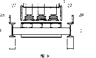
Fig. 8 is the B-B partial sectional view of Fig. 7.
The specific embodiment
Referring to Fig. 1, Fig. 2, Fig. 3, polishing machine comprises frame 1, conveyer belt 2, and a plurality of rubbing head assemblies 3 that are positioned at the conveyer belt top, and each rubbing head assembly 3 comprises grinding tool 4, drives the motor 5 that grinding tool 4 rotates.It is the mill of working face with the end face that grinding tool 4 is one.In polishing machine when work,, sheet material is placed on the conveyer belt 2, is transported to move from left to right by grinding tool 4 by conveyer belt 2 on one side and polishes grinding.Characteristics of the present utility model are that each grinding tool 4 is by motor 5 drive.With the direction that is parallel to conveyer belt 2 running trends is vertical, is horizontal stroke with the direction perpendicular to conveyer belt 2 running trends, and all grinding tools 4 are embarked on journey according to indulging, the rule of horizontal one-tenth row is arranged." vertical embark on journey, horizontal one-tenth row " not strict being arranged in a straight line of the utility model indication.Except spread pattern shown in Figure 3, another kind of arrangement regulation shown in Figure 4 also belongs to the arrangement regulation of " vertical embark on journey, horizontal one-tenth row " of the utility model indication.
For sheet material can be polished uniformly, grinding tool 4 distribution density and distributing position in the horizontal, should make every block of sheet material be cut polishing simultaneously by two file grinding tools at least in the horizontal, and the two file grinding tools that are positioned at sheet edge are just across on the edge of sheet material.With Fig. 3 is example, and sheet material 6a moves from left to right, cut polishing by two file grinding tool 4a, 4b simultaneously respectively in the horizontal, and two file grinding tool 4a, 4b is just across on the edge of sheet material 6a.As best mode, should make every block of sheet material just be cut polishing simultaneously in the horizontal by three file grinding tools, with Fig. 4 is example, sheet material 6b moves from left to right, just cut polishing simultaneously in the horizontal by three file grinding tool 4c, 4d, 4e, and sheet material 6b just by two file grinding tool 4c, 4e across on the edge.This sheet material that makes is just cut the layout type of polishing by three file grinding tools in the horizontal simultaneously, can satisfy the requirement of uniform polish, can avoid being provided with too much grinding tool and motor again and the waste that causes, obtains optimum balance between quality of finish and cost.Certainly, Fig. 4 also is applicable to the sheet material that the cross machine width is bigger, and monolithic sheet material is polished by five file grinding tools in the horizontal simultaneously.In actual applications, certain machinable sheet material width of polishing machine is in the decision of polisher design stage, so the concrete diameter of each grinding tool and distribute spacing also should decide in conjunction with above-mentioned best distribution density according to designed sheet material working width.
But, arrange that according to above-mentioned distribution density grinding tool still is difficult to overcome fully the influence of grinding tool diameter to the polishing uniformity, therefore as preferred forms, all rubbing head assemblies should be installed on the swing mechanism, the swaying direction of swing mechanism is the direction perpendicular to the conveyer belt operation, i.e. teeter.After so improving, grinding tool is polished more equably to sheet material, reach best polishing effect.The amplitude of fluctuation of swing mechanism preferably is controlled at two longitudinal edges that guarantee sheet material and is in all the time in the scope of two file grinding tools covering, makes two longitudinal edges of sheet material be in polished state all the time.Swing mechanism both can be provided with a plurality of, different rubbing head assemblies is installed on the different swing mechanisms, also a swing mechanism can only be set, the total Chengdu of all rubbing heads is installed on the same swing mechanism, as embodiment preferably, should adopt the latter.As shown in Figure 1 and Figure 2, all rubbing head assemblies 3 all are installed on the same swing mechanism, this swing mechanism comprises a bracing frame 7 that is slidingly connected with frame 1, the glide direction of bracing frame 7 is perpendicular to the traffic direction of conveyer belt 2, all rubbing head assemblies 3 are installed on the bracing frame 7, and bracing frame 7 is promoted back and forth by two hydraulic cylinders 8 (perhaps cylinder).In addition, described swing mechanism also can adopt the disclosed swing mechanism of patent No. 200520053843.4.In order to prevent that bracing frame 7 is distorted in swing process, referring to Fig. 1, Fig. 2, the two ends of present embodiment on the longitudinal direction of bracing frame 7 are respectively arranged with gear 9a, the 9b that the number of teeth equates. Gear 9a, 9b are fixed in the same rotating shaft 10.On frame 1, be fixed with two tooth bar 11a, 11b, mesh with two gear 9a, 9b respectively.Article two, the trend of tooth bar 11a, 11b is parallel with the swaying direction of bracing frame 7.When bracing frame 7 swing, tooth bar 11a, 11b with make the two ends, the left and right sides of bracing frame 7 to be synchronized with the movement cooperating of gear 9a, 9b, avoided bracing frame 7 in the process of swinging back and forth, to be distorted.
In actual production, usually can run into the situation that all has identical deformation behaviour with a collection of sheet material, for example the ceramic board that is extruded by brick machine often occurs arching up or recessed distortion, and has same deformation behaviour with the sheet material of a collection of extrusion.In order to make the polishing function polish processing to this sheet material of distortion in batch better, each the rubbing head assembly that should be polishing machine is provided with elevating mechanism.After so improving, can regulate the pressure of each grinding tool according to the deformation behaviour of sheet material aborning, thereby more effectively eliminate the distortion of sheet material the sheet material different parts.With Fig. 4 is example, the deformation characteristics of supposing the sheet material 6b among the figure is to arch upward in the shade position, the downward pressure of a file grinding tool 4d in the middle of can suitably increasing by elevating mechanism so makes the shade position of sheet material 6b bear bigger cutting force, thereby can more effectively eliminate the distortion of sheet material 6b.The used elevating mechanism of present embodiment as shown in Figure 5, grinding tool rotating shaft 12 is enclosed within the sleeve 13 slidably, sleeve 13 is fixing with bracing frame 7 by ring flange 14, be fixed with two cylinders 15 outside the sleeve 13, the piston rod of two cylinders 15 connects with grinding tool rotating shaft 12 by connector 16, between connector 16 and the grinding tool rotating shaft 12 bearing 17 is installed, bearing 17 is fixed in the grinding tool rotating shaft 12.The piston rod of cylinder 15 drives connector 16 and moves up and down, and drives grinding tool rotating shaft 12 by connector 16 again and moves up and down, and just can adjust the pressure of grinding tool to sheet material as long as adjust the pressure of cylinder 15.Except elevating mechanism shown in Figure 5, can also replace cylinder 15 with hydraulic cylinder, perhaps drive connector 16 liftings with feed screw nut's elevating mechanism, can also make whole rubbing head assembly 3 do an as a whole lifting.The internal structure of the sleeve 13 among Fig. 5 also comprises two axle sleeves 18,19 up and down, be fixed with bearing between two axle sleeves 18,19 and the sleeve 13, making two axle sleeves 18,19 can only rotate in sleeve 13 can not slide up and down, grinding tool rotating shaft 12 is enclosed within two axle sleeves 18,19 and by feather key and connects, a top axle sleeve 18 connects with motor shaft by shaft coupling 20, when motor 5 rotates, drive axle sleeve 18 by shaft coupling 20 and rotate, and then drive grinding tool rotating shaft 12 rotations.
In order to eliminate vibrations that the grinding tool high speed rotating produces influence, also should between grinding tool and grinding tool rotating shaft, damping be set to polishing effect.Referring to Fig. 6, damping comprises upper junction plate 21 and lower connecting plate 22, and upper junction plate 21 is fixed with the end of grinding tool rotating shaft 12, and lower connecting plate 22 is fixing with grinding tool 4.Upper junction plate 21 is circumferentially fixed with lower connecting plate 22 but can be axially movable, is connected with damping spring 23 between the upper and lower connecting plate 21,22.Grinding tool rotating shaft 12 drives upper junction plate 21 and rotates, driving lower connecting plate 22 by upper junction plate 21 again rotates, drive grinding tool 4 by lower connecting plate 22 at last and rotate, because can be axially movable between upper junction plate 21 and the lower connecting plate 22, therefore can play cushioning effect to the axial vibrations of grinding tool 4.As realizing the circumferentially fixing but axial preferred forms of activity of upper junction plate 21 and lower connecting plate 22, present embodiment passes upper junction plate 21 from top to bottom with alignment pin 24 and is fixed on then on the lower connecting plate 22, upper junction plate 21 offers the through hole that is slidingly matched with alignment pin 24, and damping spring 23 is enclosed within on the alignment pin 24.Alignment pin 24 transmits torsion between upper junction plate 21 and lower connecting plate 22, and being slidingly matched of alignment pin 24 and upper junction plate 21 makes to have certain axial move place between upper junction plate 21 and the lower connecting plate 22.For further improving damping effect, present embodiment also is fixed with a dividing plate 25 in the upper surface of lower connecting plate 22, is lined with damping glue 26 between dividing plate 25 and the upper junction plate 21.Damping glue 26 plays the bumper and absorbing shock effect jointly with damping spring 23.
For safety, referring to Fig. 7, Fig. 8, be preferably on the bracing frame 7 that the rubbing head assembly is installed, along the direction that is parallel to the conveyer belt operation safety door 27 of setting be set, safety door 27 is hooked on the bracing frame 7; On the frame 1 of polishing machine, along the direction that is parallel to conveyer belt operation the dash door 28 of setting is set, dash door 28 is hinged with frame 1.In polishing machine when work,, safety door 27 and dash door 28 can prevent that the grinding tool accident of rotation flies out at a high speed and hurt sb.'s feelings, and dash door 28 can also stop cooling water in the polishing process contaminated environment of splashing out.When needs are changed grinding tool, safety door 27 can be taken off from bracing frame 7.Safety door 27 preferably is divided into many fans as shown in Figure 7 in the vertical, when changing the grinding tool of diverse location, only needs safety door with the relevant position take off and gets final product.
Claims (10)
1, a kind of polishing machine, comprise frame, conveyer belt, and a plurality of rubbing head assemblies that are positioned at the conveyer belt top, the rubbing head assembly comprises grinding tool, drives the motor that grinding tool rotates, and it is the mill of working face with the end face that grinding tool is one, it is characterized in that: a grinding tool distributes a motor, each grinding tool is by a motor drive, with the direction that is parallel to the conveyer belt running trend is vertical, is horizontal stroke with the direction perpendicular to the conveyer belt running trend, and all grinding tools are embarked on journey according to indulging, the rule of horizontal one-tenth row is arranged.
2, polishing machine as claimed in claim 1, it is characterized in that: grinding tool distribution density and distributing position in the horizontal, satisfy every block of sheet material and cut polishing simultaneously by two file grinding tools at least in the horizontal, and the two file grinding tools that are positioned at sheet edge are just across on the edge of sheet material.
3, polishing machine as claimed in claim 2 is characterized in that: grinding tool distribution density and distributing position in the horizontal, satisfy every block of sheet material and just cut polishing simultaneously by three file grinding tools in the horizontal.
4, polishing machine as claimed in claim 1 is characterized in that: all rubbing head assemblies are installed on the swing mechanism, and the swaying direction of swing mechanism is the direction perpendicular to the conveyer belt operation.
5, polishing machine as claimed in claim 4, it is characterized in that: the total Chengdu of all rubbing heads is installed on the same swing mechanism, described swing mechanism comprises a bracing frame that is slidingly connected with frame, the glide direction of bracing frame is perpendicular to the traffic direction of conveyer belt, and all rubbing head assemblies are installed on the bracing frame.
6, polishing machine as claimed in claim 1 is characterized in that: each rubbing head assembly is provided with elevating mechanism.
7, polishing machine as claimed in claim 1, it is characterized in that: be provided with damping between grinding tool and the grinding tool rotating shaft, described damping comprises upper junction plate and lower connecting plate, the end of upper junction plate and grinding tool rotating shaft is fixed, lower connecting plate and grinding tool are fixed, upper junction plate and lower connecting plate are circumferentially fixing but axially movable, are connected with damping spring between the upper and lower connecting plate.
8, polishing machine as claimed in claim 7, it is characterized in that: the syndeton that upper junction plate and lower connecting plate are circumferentially fixing but axially movable, be to pass upper junction plate from top to bottom with alignment pin to be fixed on the lower connecting plate then, upper junction plate offers the through hole that is slidingly matched with alignment pin, and damping spring is enclosed within on the alignment pin.
9, polishing machine as claimed in claim 8 is characterized in that: also be fixed with a dividing plate in the upper surface of lower connecting plate, be lined with damping glue between dividing plate and the upper junction plate.
10, polishing machine as claimed in claim 5 is characterized in that: on the bracing frame that the rubbing head assembly is installed, be provided with the safety door of setting along the direction that is parallel to the conveyer belt operation, safety door is hooked on the bracing frame; On the frame of polishing machine, be provided with the dash door of setting along the direction that is parallel to conveyer belt operation, dash door and frame are hinged.
Priority Applications (1)
| Application Number | Priority Date | Filing Date | Title |
|---|---|---|---|
| CN 200620062692 CN200967166Y (en) | 2006-08-03 | 2006-08-03 | Polishers |
Applications Claiming Priority (1)
| Application Number | Priority Date | Filing Date | Title |
|---|---|---|---|
| CN 200620062692 CN200967166Y (en) | 2006-08-03 | 2006-08-03 | Polishers |
Publications (1)
| Publication Number | Publication Date |
|---|---|
| CN200967166Y true CN200967166Y (en) | 2007-10-31 |
Family
ID=38966738
Family Applications (1)
| Application Number | Title | Priority Date | Filing Date |
|---|---|---|---|
| CN 200620062692 Expired - Fee Related CN200967166Y (en) | 2006-08-03 | 2006-08-03 | Polishers |
Country Status (1)
| Country | Link |
|---|---|
| CN (1) | CN200967166Y (en) |
Cited By (28)
| Publication number | Priority date | Publication date | Assignee | Title |
|---|---|---|---|---|
| CN102320024A (en) * | 2011-09-23 | 2012-01-18 | 陈勇 | Polishing device |
| CN103029025A (en) * | 2012-12-12 | 2013-04-10 | 大连恒喆木工机械制造有限公司 | Disk-type polishing machine |
| CN103331682A (en) * | 2013-07-22 | 2013-10-02 | 上海西戈玛不锈钢有限公司 | Novel polishing machine |
| CN103357604A (en) * | 2013-07-31 | 2013-10-23 | 攀钢集团工程技术有限公司 | Cleaning device for cleaning sheet bar of heat exchanger |
| CN104309010A (en) * | 2014-10-13 | 2015-01-28 | 佛山市禾才科技服务有限公司 | Semi-finished product surface treatment equipment |
| CN104309009A (en) * | 2014-10-13 | 2015-01-28 | 佛山市禾才科技服务有限公司 | Semi-finished product surface treatment equipment |
| CN104309007A (en) * | 2014-10-13 | 2015-01-28 | 佛山市禾才科技服务有限公司 | Semi-finished product surface treatment equipment |
| CN104309011A (en) * | 2014-10-13 | 2015-01-28 | 佛山市禾才科技服务有限公司 | Surface treatment equipment for semi-finished product |
| CN104309005A (en) * | 2014-10-13 | 2015-01-28 | 佛山市禾才科技服务有限公司 | Surface treatment equipment for semi-finished product |
| CN104309008A (en) * | 2014-10-13 | 2015-01-28 | 佛山市禾才科技服务有限公司 | Surface treatment equipment for semi-finished product |
| CN104309004A (en) * | 2014-10-13 | 2015-01-28 | 佛山市禾才科技服务有限公司 | Semi-finished product surface treatment equipment |
| CN104440468A (en) * | 2014-10-13 | 2015-03-25 | 佛山市禾才科技服务有限公司 | Semi-finished product surface treatment equipment |
| CN104842252A (en) * | 2014-02-15 | 2015-08-19 | 深圳富泰宏精密工业有限公司 | Polishing machine |
| CN104942690A (en) * | 2015-07-17 | 2015-09-30 | 厦门理工学院 | Elastic polishing device and method for irregular workpiece |
| CN105290725A (en) * | 2015-08-05 | 2016-02-03 | 上海罗特钢带有限公司 | Method of preparing high-precision annular grinding mirror surface steel belt |
| CN105479303A (en) * | 2016-01-21 | 2016-04-13 | 华寿庆 | Building board surface polishing machine |
| CN105798743A (en) * | 2016-05-16 | 2016-07-27 | 厦门思尔特机器人系统股份公司 | Through-feed polishing system |
| CN105945673A (en) * | 2015-05-28 | 2016-09-21 | 海宁奇晟轴承有限公司 | External cylindrical superfinishing machine for machining bearing ring |
| CN106112765A (en) * | 2016-08-16 | 2016-11-16 | 无锡尊宝电动车有限公司 | A kind of metal surface treating apparatus |
| CN106217160A (en) * | 2016-06-23 | 2016-12-14 | 蒋学光 | Foundry goods edge sanding apparatus |
| CN106271999A (en) * | 2016-08-26 | 2017-01-04 | 淄博狮王陶瓷有限公司 | A kind of method that polished bricks surface is carried out flexible selection type rough polishing and polished bricks rough polishing machine |
| CN106272012A (en) * | 2016-08-10 | 2017-01-04 | 佛山市思特四通化工有限公司 | A kind of quartz sample block polishing filming equipment and processing method |
| CN106514478A (en) * | 2017-01-04 | 2017-03-22 | 广东鼎科技有限公司 | Efficient polishing machine |
| CN109048529A (en) * | 2018-09-18 | 2018-12-21 | 洛阳理工学院 | A kind of nonmetal plate grinding and polishing apparatus |
| CN109227337A (en) * | 2018-10-10 | 2019-01-18 | 徐州格非家居有限公司 | A kind of large size furniture polish device |
| WO2019080597A1 (en) * | 2017-10-26 | 2019-05-02 | 广东科达洁能股份有限公司 | Ceramic tile polishing apparatus having a multiple-row arrangement of polishing abrasive heads, and technique |
| CN111300248A (en) * | 2019-11-25 | 2020-06-19 | 衡阳阳光陶瓷有限公司 | Burnishing machine that ceramic machining used |
| CN113664691A (en) * | 2021-08-03 | 2021-11-19 | 南京工大数控工具有限公司 | Intelligent multi-station polishing machine tool |
-
2006
- 2006-08-03 CN CN 200620062692 patent/CN200967166Y/en not_active Expired - Fee Related
Cited By (32)
| Publication number | Priority date | Publication date | Assignee | Title |
|---|---|---|---|---|
| CN102320024A (en) * | 2011-09-23 | 2012-01-18 | 陈勇 | Polishing device |
| CN103029025A (en) * | 2012-12-12 | 2013-04-10 | 大连恒喆木工机械制造有限公司 | Disk-type polishing machine |
| CN103331682A (en) * | 2013-07-22 | 2013-10-02 | 上海西戈玛不锈钢有限公司 | Novel polishing machine |
| CN103357604A (en) * | 2013-07-31 | 2013-10-23 | 攀钢集团工程技术有限公司 | Cleaning device for cleaning sheet bar of heat exchanger |
| CN104842252B (en) * | 2014-02-15 | 2017-08-08 | 赛恩倍吉科技顾问(深圳)有限公司 | Polishing machine |
| CN104842252A (en) * | 2014-02-15 | 2015-08-19 | 深圳富泰宏精密工业有限公司 | Polishing machine |
| CN104309007A (en) * | 2014-10-13 | 2015-01-28 | 佛山市禾才科技服务有限公司 | Semi-finished product surface treatment equipment |
| CN104309011A (en) * | 2014-10-13 | 2015-01-28 | 佛山市禾才科技服务有限公司 | Surface treatment equipment for semi-finished product |
| CN104309005A (en) * | 2014-10-13 | 2015-01-28 | 佛山市禾才科技服务有限公司 | Surface treatment equipment for semi-finished product |
| CN104309008A (en) * | 2014-10-13 | 2015-01-28 | 佛山市禾才科技服务有限公司 | Surface treatment equipment for semi-finished product |
| CN104309004A (en) * | 2014-10-13 | 2015-01-28 | 佛山市禾才科技服务有限公司 | Semi-finished product surface treatment equipment |
| CN104440468A (en) * | 2014-10-13 | 2015-03-25 | 佛山市禾才科技服务有限公司 | Semi-finished product surface treatment equipment |
| CN104309009A (en) * | 2014-10-13 | 2015-01-28 | 佛山市禾才科技服务有限公司 | Semi-finished product surface treatment equipment |
| CN104309010A (en) * | 2014-10-13 | 2015-01-28 | 佛山市禾才科技服务有限公司 | Semi-finished product surface treatment equipment |
| CN105945673B (en) * | 2015-05-28 | 2018-01-05 | 海宁奇晟轴承有限公司 | A kind of external cylindrical superfinishing machine for processing bearing ring |
| CN105945673A (en) * | 2015-05-28 | 2016-09-21 | 海宁奇晟轴承有限公司 | External cylindrical superfinishing machine for machining bearing ring |
| CN104942690A (en) * | 2015-07-17 | 2015-09-30 | 厦门理工学院 | Elastic polishing device and method for irregular workpiece |
| CN105290725A (en) * | 2015-08-05 | 2016-02-03 | 上海罗特钢带有限公司 | Method of preparing high-precision annular grinding mirror surface steel belt |
| CN105290725B (en) * | 2015-08-05 | 2018-08-28 | 上海罗特钢带系统股份有限公司 | A method of preparing high-precision annular abrasion minute surface steel band |
| CN105479303A (en) * | 2016-01-21 | 2016-04-13 | 华寿庆 | Building board surface polishing machine |
| CN105798743A (en) * | 2016-05-16 | 2016-07-27 | 厦门思尔特机器人系统股份公司 | Through-feed polishing system |
| CN105798743B (en) * | 2016-05-16 | 2018-07-06 | 厦门航天思尔特机器人系统股份公司 | One kind passes through formula polishing system |
| CN106217160A (en) * | 2016-06-23 | 2016-12-14 | 蒋学光 | Foundry goods edge sanding apparatus |
| CN106272012A (en) * | 2016-08-10 | 2017-01-04 | 佛山市思特四通化工有限公司 | A kind of quartz sample block polishing filming equipment and processing method |
| CN106112765A (en) * | 2016-08-16 | 2016-11-16 | 无锡尊宝电动车有限公司 | A kind of metal surface treating apparatus |
| CN106271999A (en) * | 2016-08-26 | 2017-01-04 | 淄博狮王陶瓷有限公司 | A kind of method that polished bricks surface is carried out flexible selection type rough polishing and polished bricks rough polishing machine |
| CN106514478A (en) * | 2017-01-04 | 2017-03-22 | 广东鼎科技有限公司 | Efficient polishing machine |
| WO2019080597A1 (en) * | 2017-10-26 | 2019-05-02 | 广东科达洁能股份有限公司 | Ceramic tile polishing apparatus having a multiple-row arrangement of polishing abrasive heads, and technique |
| CN109048529A (en) * | 2018-09-18 | 2018-12-21 | 洛阳理工学院 | A kind of nonmetal plate grinding and polishing apparatus |
| CN109227337A (en) * | 2018-10-10 | 2019-01-18 | 徐州格非家居有限公司 | A kind of large size furniture polish device |
| CN111300248A (en) * | 2019-11-25 | 2020-06-19 | 衡阳阳光陶瓷有限公司 | Burnishing machine that ceramic machining used |
| CN113664691A (en) * | 2021-08-03 | 2021-11-19 | 南京工大数控工具有限公司 | Intelligent multi-station polishing machine tool |
Similar Documents
| Publication | Publication Date | Title |
|---|---|---|
| CN200967166Y (en) | Polishers | |
| CN101279436B (en) | Multiple-array staggered form polisher | |
| CN105813806A (en) | Machine for smoothing and/or polishing slabs of stone material, such as natural or agglomerated stone, ceramic and glass | |
| CN109926879A (en) | A kind of stone material automatic polishing machine | |
| CN201415355Y (en) | Dual-row multi-head automatic stone material grinding machine | |
| CN104842255A (en) | Polishing machine | |
| CN202357029U (en) | Surface polishing machine for artificial boards | |
| CN209380496U (en) | A kind of glass polishing machine | |
| CN100467220C (en) | Method of eliminating arc deformation of polished brick and the polishing machine therefor | |
| CN100586655C (en) | Automatic surface grinder for crystal glass | |
| CN105291276B (en) | Intelligent machining device and method for profiling cutting head and multi-face profiling stone | |
| CN1654164A (en) | Environment-friendly type high precision sander | |
| CN208645102U (en) | A kind of automatic sand-blasting machine of SERVO CONTROL rapid translation spray head | |
| CN100519069C (en) | Ceramic polishing brick surface processing method and device | |
| CN217701526U (en) | Flexible rotating tool for milling machine | |
| CN202825470U (en) | Multi-functional glass processing equipment | |
| CN201030500Y (en) | Stone grinder | |
| CN207027749U (en) | The facing cut of timber four | |
| CN105171592A (en) | Glass ceramic continuous polishing machine | |
| CN202240756U (en) | Multifunctional polishing and burnishing machine | |
| CN101396801A (en) | Water mil | |
| CN210060620U (en) | Automatic stone polishing machine | |
| CN201214209Y (en) | Porcelain brick/stone polisher for balancing supported beam gravity center | |
| CN103341808A (en) | Full-automatic cambered surface grinding device for spiral tool bit of tile tool and application method thereof | |
| CN202114587U (en) | Water finishing machine |
Legal Events
| Date | Code | Title | Description |
|---|---|---|---|
| C14 | Grant of patent or utility model | ||
| GR01 | Patent grant | ||
| C17 | Cessation of patent right | ||
| CF01 | Termination of patent right due to non-payment of annual fee |
Granted publication date: 20071031 Termination date: 20100803 |