CN1966342A - Motorcycle - Google Patents
Motorcycle Download PDFInfo
- Publication number
- CN1966342A CN1966342A CNA200610145701XA CN200610145701A CN1966342A CN 1966342 A CN1966342 A CN 1966342A CN A200610145701X A CNA200610145701X A CN A200610145701XA CN 200610145701 A CN200610145701 A CN 200610145701A CN 1966342 A CN1966342 A CN 1966342A
- Authority
- CN
- China
- Prior art keywords
- vehicle
- case beam
- motor bike
- width direction
- capping
- Prior art date
- Legal status (The legal status is an assumption and is not a legal conclusion. Google has not performed a legal analysis and makes no representation as to the accuracy of the status listed.)
- Granted
Links
Images


Classifications
-
- B—PERFORMING OPERATIONS; TRANSPORTING
- B62—LAND VEHICLES FOR TRAVELLING OTHERWISE THAN ON RAILS
- B62J—CYCLE SADDLES OR SEATS; AUXILIARY DEVICES OR ACCESSORIES SPECIALLY ADAPTED TO CYCLES AND NOT OTHERWISE PROVIDED FOR, e.g. ARTICLE CARRIERS OR CYCLE PROTECTORS
- B62J17/00—Weather guards for riders; Fairings or stream-lining parts not otherwise provided for
- B62J17/02—Weather guards for riders; Fairings or stream-lining parts not otherwise provided for shielding only the rider's front
-
- B—PERFORMING OPERATIONS; TRANSPORTING
- B62—LAND VEHICLES FOR TRAVELLING OTHERWISE THAN ON RAILS
- B62J—CYCLE SADDLES OR SEATS; AUXILIARY DEVICES OR ACCESSORIES SPECIALLY ADAPTED TO CYCLES AND NOT OTHERWISE PROVIDED FOR, e.g. ARTICLE CARRIERS OR CYCLE PROTECTORS
- B62J23/00—Other protectors specially adapted for cycles
-
- B—PERFORMING OPERATIONS; TRANSPORTING
- B62—LAND VEHICLES FOR TRAVELLING OTHERWISE THAN ON RAILS
- B62K—CYCLES; CYCLE FRAMES; CYCLE STEERING DEVICES; RIDER-OPERATED TERMINAL CONTROLS SPECIALLY ADAPTED FOR CYCLES; CYCLE AXLE SUSPENSIONS; CYCLE SIDE-CARS, FORECARS, OR THE LIKE
- B62K11/00—Motorcycles, engine-assisted cycles or motor scooters with one or two wheels
- B62K11/02—Frames
- B62K11/04—Frames characterised by the engine being between front and rear wheels
Abstract
The invention provides a motorcycle with an improved external appearance of the head pipe neighboring section of tank rails. Left and right tank rails are formed such that a vehicle width direction space becomes narrower adjacent to the head pipe as the tank rails extend toward the head pipe side. Left and right body covers have a front side neighboring section adjacent to a front side outer side section of the tank rails, a rear side neighboring section further to the rear and further to the outer side in the vehicle width direction than the front side neighboring section, and an overhanging surface that is continuous with the front side neighboring section in plan view, and that is disposed to the side of the front side outer side section such that the overhanging surface protrudes outwards in the vehicle width direction from the front side outer side section of the tank rails.
Description
Technical field
The present invention relates to motor bike, it comprises the vehicle body capping on a pair of left and right sides case beam that pipe from the beginning extends along the vehicle backward directions and the vehicle outside that is arranged on left and right sides case beam.
Background technology
As the example of this type motor bike, for example patent document 1 has proposed a kind of structure, and wherein engine installation is below the case beam of the left and right sides, and radiator navigates to the front side of driving engine.The radiator capping that the wind of advancing is incorporated into radiator is arranged on the vehicle outside of left and right sides case beam.
The radiator capping has the structure that comprises upper lateral part and following side.Upper lateral part forms along adjacent with the head pipe head pipe adjacency section of case beam and extends, and the following side is formed with from upper lateral part continuously and scatter laterally on vehicle-width direction and be fan-shaped curved shape.
[patent documentation 1] Japanese Patent No.2979015
Summary of the invention
But for above-mentioned known motor bike, the upper lateral part of radiator capping forms along the head pipe adjacency section of case beam and extends.As a result, this structure does not have the outward appearance that can produce strong and solid impression, as to center on case beam head pipe adjacency section.More specifically, the head pipe adjacency section of left and right sides case beam tilts to the inside, makes the vehicle width space along with head pipe adjacency section is extended and become narrower towards head pipe side.The radiator capping is set makes it, caused that the outward appearance of the head pipe peripheral region of case beam can not produce bigger impression along this part extension of bevelled to the inside in this way.
The above-mentioned situation of considering prior art has designed the present invention, and its objective is a kind of motor bike is provided, and can improve the outward appearance of the head pipe adjacency section of case beam.
The invention is characterized in, comprising head pipe, be arranged into the motor bike of vehicle body capping in each outside of described left and right sides case beam at the rearward upwardly extending left and right sides of vehicle case beam with at vehicle-width direction from described pipe, described left and right sides case beam forms and makes and at one the vehicle-width direction space between the outside portion is become narrower near described pipe, and described vehicle-width direction space is along with described outside portion is extended and become narrower towards described head pipe side; And the vehicle body capping of the described left and right sides has the adjacency section, front side respectively, and it is arranged as adjacent with the preceding outside portion of close described pipe of each case beam; The rear side adjacency section, its be arranged in than adjacency section, described front side on the vehicle fore-and-aft direction more by the back and on vehicle-width direction more in the outer part position, make described rear side adjacency section adjacent further from the back outside portion of described pipe with the described preceding outside portion of the ratio of each case beam; With stretch out the surface, when observing in birds-eye view, itself and adjacency section, described front side are continuous, and are arranged in towards the position of that side of described preceding outside portion, make that the described described preceding outside portion from described case beam on vehicle-width direction, surface of stretching out is outwards outstanding.
According to motor bike of the present invention, described vehicle body capping has preceding outside portion and the adjacency section, front side of outside portion, back case beam and the structure of rear side adjacency section that comprises with the case beam.In addition, the vehicle body capping has and is included on the vehicle-width direction the outwards outstanding structure of stretching out the surface in outside portion in the past.As a result, when the frame shape that wherein the head pipe adjacency section of left and right sides case beam becomes narrower is provided, can give the vehicle body capping a kind of firm and three dimensional shapes.In addition, the zone around the head pipe has showed its bigger more sound impression, thereby and has an outward appearance that produces strong and solid impression.
Description of drawings
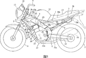
Fig. 1 is the lateral plan according to the motor bike of the embodiment of the invention.
Fig. 2 is the lateral plan of the preceding capping of motor bike.
Fig. 3 is the birds-eye view of preceding capping.
Fig. 4 is the front elevation of preceding capping.
Fig. 5 illustrates the birds-eye view that concerns between preceding capping and the case beam.
Fig. 6 is the cutaway view (cutaway view of being got along the line VI-VI of Fig. 3) of preceding capping.
Fig. 7 is the cutaway view (cutaway view of being got along the line VII-VII of Fig. 2) of preceding capping.
Fig. 8 is the cutaway view (cutaway view of being got along the line VIII-VIII of Fig. 2) of preceding capping.
The specific embodiment
After this, embodiments of the invention will be described with reference to the drawings.
Fig. 1 to Fig. 8 is the figure that explains according to the motor bike of the embodiment of the invention.Notice that the term front, rear, left and right of Shi Yonging are represented by the observed front, rear, left and right of rider that are positioned on the vehicle seat in the present embodiment.In addition, the term that uses in the present embodiment upper and lower be illustrated in the road surface vertical direction on upper and lower.
In the drawings, the body shell of 1 expression motor bike.This body shell 1 comprises head pipe 2; From the beginning manage the left and right sides case beam 3,3 of 2 diagonal angle extensions downwards on the vehicle backward directions; The back arm support 4,4 that extends continuously downwards from each rear end of left and right sides case beam 3,3; From left and right sides case beam 3,3 at the vehicle backward directions vehicle seat beam 5,5 that extends of diagonal angle upwards; And with the suspension mode be arranged in left and right sides vehicle seat beam 5,5 and about the vehicle seat stay 6,6 of back between the arm support 4,4.
The leading section of postbrachium 10 by about back arm support 4 support, make the leading section of postbrachium 10 to swing up and down.The rearward end of postbrachium 10 is supported trailing wheel 11 pivotly.
Watercooled engine 20 is installed in the below of left and right sides case beam 3,3.Driving engine 20 has the bolt fastening structure that comprises the crankcase 22 that holds bent axle 21.Cylinder block 23, cylinder head 24 and cylinder head cover 25 are stacked on the assembly surface on the top of crankcase 22, and bolted arrives it.
Comprise the change speed gear box 22a of transmission system (not shown) and the rear portion of crankcase 22 and form one.The axle drive shaft 26 that is arranged in the rear portion of change speed gear box 22 rotatably drives trailing wheel 11 via chain 26a.
Freeing pipe 27 is connected to the front wall portion of cylinder head 24.Freeing pipe 27 extends downwards from front wall portion, through driving engine 20 belows, rearward extends upward at vehicle, and is connected to the silencer 28 on the right side that is arranged in trailing wheel 11.
The rear wall parts of cylinder head 24 is connected to free air diffuser 29.Free air diffuser 29 is extending below fuel tank 12 on the backward directions, and is connected to the airfilter (not shown).
The left upper wall portions of radiator 30 is by the fastening radiator bearer 32 that is fixed to of bolt 32a, and radiator bearer 32 is attached to the lower surface of right case beam 3.The bottom, left side of radiator 30 is fixed to cylinder head 24 via arm support 31 by bolted.Notice that the right upper wall portions of radiator 30 is fixed to radiator bearer 32 by pin 32b, thus and location.
Left and right sides case beam the 3, the 3rd has the protruding part of four prism type, its have the size on the above-below direction greater than vehicle-width direction on the cross-sectional plane of long limit rectangle of size.Along with left and right sides case beam 3,3 extends to its front side from its rear side, their size on above-below direction becomes bigger gradually.The leading section 3a of the conduct head pipe transom of left and right sides case beam 3 has and is set equal to or less than the above-below direction size h1 of the axial dimension h2 of head pipe 2.Like this, because the above-below direction size h1 of case beam 3 equals the axial dimension h2 of head pipe 2 substantially, so can improve the Joint strenght and the rigidity of left and right sides case beam 3 and head pipe 2.In addition, this structure can be born to apply and be managed 2 and the big moment of flexure of the connecting portion of leading section 3a to the end.
When observing in birds-eye view, left and right sides case beam 3,3 has on the vehicle fore-and-aft direction linearly extended straight portion 3c, 3c and extends and along with it extends and have inboard rake 3b, a 3b in narrower vehicle width space to head pipe 2 from the front end of straight portion 3c, 3c.About the leading section 3a welding of inboard rake 3b, 3b manage 2 to the end.Note, about the interior angle of inboard rake 3b, 3b be set at about 60 degree.In addition, leg-of- mutton gusset 33,34 up and down engages by upper surface and the lower surface of inboard rake 3b, 3b about being welded to.In addition, the outside portion of the inboard rake 3b of case beam 3 has formed the preceding outside portion of close head pipe 2, and the outside portion of straight portion 3c has formed the back outside portion away from head pipe 2.
The left and right sides capping 38,38 that left and right sides vehicle seat beam 5,5 and vehicle seat stay 6,6 are formed from a resin covers.When observing vehicle from the side, left and right sides capping 38 has upside-down triangle shape substantially, and has the front edge 38a that extends along the upper surface of case beam 3; The upper limb 38b that extends along the lower edge portion of fuel tank 12; And the lower edge 38c that extends along vehicle seat stay 6.
In addition, the resin preceding capping 40,40 of making is arranged on the vehicle outside of left and right sides case beam 3,3.About before capping 40,40 be incorporated into the air collector of radiator 30 as the wind that will travel, and also as the trim board that covers between case beam 3, driving engine 20 and the cylinder head cover 25, thereby improve outward appearance.Note, about before capping 40,40 have the shape of basic left and right sides line symmetry.The explanation that this literary composition provides will mainly concentrate on left front capping 40.
Left front capping 40 is extended and the outside of radiator cover 30 and the lower part 40b in the gap between case beam 3 and the cylinder head cover 25 form continuously by the first half 40a of the lateral wall that covers left case beam 3 with from first half 40a.When observing from the side, left front capping 40 has side V-arrangement substantially.In addition, preceding capping 40 is the three-dimensional structures with a plurality of continuous surface A-F, and a plurality of continuous surface A-F have the border that is formed by edge line a1-a5, and has the different angles with respect to edge line.
When observing from the side, edge line a1 forms such shape, it is a basic side V-arrangement, and extends diagonally forward and downwards along the cardinal principle center of the fore-and-aft direction of first half 40a, and extends to the rear downwards diagonally along the border of first half 40a and lower part 40b.Edge line a2, a3 extend to the place ahead respectively downwards diagonally and extend to the rear downwards diagonally along the side V-arrangement of edge line a1.In addition, edge line a4, a5 extend between the upper end of edge line a1 and a2, a3 and bottom, and upper end and the bottom of adjoining edge line a1 and a2, a3.
And, form the expansion continuous surface A that expands and have basic side V-arrangement shape at outward direction from case beam 3 by edge line a1, a2, a3, a4, a5 region surrounded.In addition, the rear lateral portion of edge line a1 forms side V-arrangement, paddy shape continuous surface B substantially.
In addition, formed with curved shape upside vehicle-width direction continuous surface C towards the outer surface extension of case beam 3 on vehicle-width direction by the upside front edge 40c institute region surrounded of edge line a2 and first half 40a.
And, formed the downside vehicle-width direction continuous surface D that on vehicle-width direction, extends with curved shape towards the inboard by the downside front edge 40d region surrounded of edge line a3 and lower part 40b.In addition, formed upper limb continuous surface E by the upper limb 40e region surrounded of edge line a4 and first half 40a with the shape of extending and extending along this upper limb towards the upper limb of case beam 3 with curved shape.Lower edge 40f region surrounded by edge line a5 and lower part 40b has formed lower edge continuous surface F.
When observing in birds-eye view, the vehicle-width direction medial end of upside vehicle-width direction continuous surface C has formed adjacent adjacency section, the front side C1 of preceding outside portion 3b near head pipe 3 with case beam 3.In addition, the rearward end of upper limb continuous surface E formed be arranged in than adjacency section, front side C1 on the vehicle fore-and-aft direction more by the back and on vehicle-width direction more outer rear side adjacency section E1, the back outside portion 3c away from head pipe 3 of rear side adjacency section E1 and case beam 3 is adjacent thus.Rear side adjacency section E1 and adjacency section, front side C1 both are positioned near the upper limb of case beam 3.
And, the top of expansion continuous surface A formed be arranged in towards the position of the sidepiece of preceding outside portion 3b stretch out surfaces A 1, make that to stretch out surfaces A 1 preceding outside portion 3b from case beam 3 on vehicle-width direction outwards outstanding.In addition, stretch out surfaces A 1 and formed on the fore-and-aft direction of vehicle the fore-and-aft direction continuous surface that extends continuously from the adjacent part of rear side adjacency section E1.
When observing vehicle from the side, the vehicle-width direction continuous surface C of the edge that goes forward of capping 40 navigates to the rear and the below of head lamp 15 before being positioned at.As a result, head lamp 15 is exposed to sidepiece.In addition, the leading section G of preceding capping 40 extends to itself and the bottom of head pipe 2 and a part of position overlapped of front fork 7.
The recess 48 that is roughly V-arrangement is formed among the paddy shape continuous surface B that is positioned to edge line a1 rear.The edge B1 and extend diagonally backward and downwards and the tilt edge B2 overlapping of having a down dip that recess 48 has from the upper limb rear end forward and extends diagonally downwards with the lower edge portion of case beam 3 from the lower end of the edge B1 that has a down dip.As the result of recess 48, exposed the lateral wall of case beam 3.
Before the front inner surface of the capping 40 horizontal ribs 40h that is formed with the vertical rib 40g that on above-below direction, extends point-blank and forwards projecting upwards from the above-below direction middle part of vertical rib 40g.
Rearwardly projecting attaching rib 40i is formed on the bottom of the vertical rib 40g of lower part 40b.This attaching rib 40i is fixed to the diapire of the case 30c of radiator 30 by the locating dowel pin 41 that comprises resilient bushing.
Attaching seat 40j forms caving inward in the rearward end of lower part 40b.This attaching seat 40j is fixed to capping support 42 by the bolt (not shown) that is screwed into from the outside, and capping support 42 is fixed to case beam 3.
Having to the inside, the positioning rib 40b that cuts hole 40m of opening is formed among the rear side adjacency section E1 of first half 40b.The hole 40m that cuts of positioning rib 40n is assembled to the locating dowel pin 46 of the lateral wall that is fixed to case beam 3 via resilient bushing 47, thus capping 40 moving on above-below direction, fore-and-aft direction and inside vehicle-width direction before regulating.As the result who adopts this structure, preceding capping 40 is attached to case beam 3 and radiator 30, and all stays space largely with respect to case beam 3 on above-below direction and fore-and-aft direction.
According to present embodiment, following structure is adopted in preceding capping 40, comprising: the front side adjacency section C1 adjacent with the preceding outside portion 3b of left and right sides case beam 3,3; With the adjacent rear side adjacent part E1 of back outside adjacency section 3c; And with respect to the preceding outside portion 3b of the case beam 3 outwards outstanding surfaces A 1 of stretching out on vehicle-width direction.Therefore, in the frame shape that the head pipe adjacency section that its raising middle flask beam 3 is provided becomes narrower, can give the vehicle body capping 40 1 kinds of firm and three dimensional shapes.In addition, the head pipe adjacency section of case beam 3 has showed its bigger more sound impression, thereby and has an outward appearance that produces strong and solid impression.
In this structure, stretch out surfaces A 1 and formed the fore-and-aft direction continuous surface that extends forward continuously from adjacency section, front side E1.As a result, compare with the preceding outside portion 3b of case beam 3, this continuous surface reaches the outside relatively on vehicle-width direction, has firm and three-dimensional outward appearance and uncomplicated shape thereby preceding capping 40 is provided with.
In the present embodiment, vehicle-width direction continuous surface C extends from the upper limb that stretches out surfaces A 1 continuously to the inside with curved shape.As a result, this continuous surface C has filled the space of stretching out between surfaces A 1 and the case beam 3, thereby has further strengthened the firm impression that is produced by preceding capping 40.
Be formed on adjacency section, front side C1 among the vehicle-width direction continuous surface C by be fixed to the capping support 45 of case beam 3 from the bolt 44 that is screwed into.Therefore, the attaching of preceding capping 40 operation is simple, and bolt 44 is orientated as and made that it is not obvious when observing vehicle from the side.
In the present embodiment, be positioned at before the vehicle-width direction continuous surface C of last forward edge of capping 40 navigate to the rear and the below of head lamp 15.As a result, head lamp 15 is exposed to the outside, and the zone around the head lamp 15 has clean and clean and tidy outward appearance.
In addition, the leading section G of preceding capping extends to a part of position overlapped of the bottom that comprises head pipe 2 of itself and front fork 7.Therefore, the amount that is incorporated into the wind that travels of radiator 30 can increase and can improve cooling effectiveness.
In the present embodiment, preceding capping 40 has the structure that comprises a plurality of continuous surface A-F, and a plurality of continuous surface A-F have the border that is formed by edge line a1-a5, and has the different angles with respect to it.Therefore, the rigidity of capping 40 before can improving, and preceding capping 40 has the outward appearance of making us with deep impression and producing firm impression.
In the present embodiment, the recess 48 that is roughly V-arrangement is formed among the paddy shape continuous surface B at the rear that is positioned edge line a1, and exposes the lateral wall of case beam 3 by recess 48.Therefore, can also further strengthen the outward appearance in preceding capping 40 zone on every side.
In addition, in the present embodiment, the lower edge portion of tilt edge B2 and the case beam 3 of paddy shape continuous surface B is overlapping.Therefore, between case beam 3 and preceding capping 40, there is not the gap, and, strengthened outward appearance yet with respect to this point.
Note, in the explanation of present embodiment, about before capping 40 wind that will travel be incorporated into radiator 30.But, of the present invention before capping 40 wind that can certainly be applied to wherein to travel be introduced in the structure of air cooling driving engine.
Claims (15)
1. motor bike comprises the head pipe, is arranged into the vehicle body capping in each outside of described left and right sides case beam from described pipe at the rearward upwardly extending left and right sides of vehicle case beam with at vehicle-width direction, and described motor bike is characterised in that:
Described left and right sides case beam forms and makes and at one the vehicle-width direction space between the outside portion is become narrower near described pipe, and described vehicle-width direction space is along with described outside portion is extended and become narrower towards described head pipe side; And
The vehicle body capping of the described left and right sides has respectively: the adjacency section, front side, and it is arranged as adjacent with the preceding outside portion of close described pipe of each case beam; The rear side adjacency section, its be arranged in than adjacency section, described front side on the vehicle fore-and-aft direction more by the back and on vehicle-width direction more in the outer part position, make described rear side adjacency section adjacent further from the back outside portion of described pipe with the described preceding outside portion of the ratio of each case beam; With stretch out the surface, when observing in birds-eye view, itself and adjacency section, described front side are continuous, and are arranged in towards the position of that side of described preceding outside portion, make that the described described preceding outside portion from described case beam on vehicle-width direction, surface of stretching out is outwards outstanding.
2. motor bike according to claim 1 is characterized in that, the described surface of stretching out has formed adjacent part from described rear side adjacency section continuous fore-and-aft direction continuous surface on the vehicle fore-and-aft direction.
3. motor bike according to claim 1, it is characterized in that, comprise the upper limb successive cars Width continuous surface that stretches out the surface from described, described vehicle-width direction continuous surface extends towards the described preceding outside portion of described case beam, and extends to the inboard of vehicle-width direction with curved shape at a predetermined angle.
4. motor bike according to claim 3 is characterized in that, the attaching portion that is used for described vehicle body capping is attached to described case beam is formed on described vehicle-width direction continuous surface.
5. motor bike according to claim 1, it is characterized in that when observing described vehicle from the side, the upper edge of each vehicle body capping is arranged in the rear or the below of the vehicle fore-and-aft direction of head lamp, so that described head lamp is exposed to sidepiece, described head lamp is arranged into the front side of described pipe.
6. motor bike according to claim 5 is characterized in that, when observing described vehicle from the side, the front edge portion of each vehicle body capping extends at least a portion position overlapped with described pipe.
7. motor bike according to claim 5 is characterized in that, when observing described vehicle from the side, the front edge portion of each vehicle body capping extends at least a portion position overlapped with the front fork that is supported by described head pipe.
8. motor bike according to claim 1 is characterized in that the outer surface of each vehicle body capping has a plurality of continuous surfaces, and described a plurality of continuous surfaces have the border that is formed by edge line, and has the different angles with respect to described edge line.
9. motor bike according to claim 1 is characterized in that, engine installation is below described case beam, and described vehicle body capping is arranged as the covering sidepiece, the feasible inside that can not see between described driving engine and the described case beam.
10. motor bike according to claim 1 is characterized in that, described case beam has the outside portion of upwards expanding below basically.
11. motor bike according to claim 10 is characterized in that, the above-below direction of the leading section of described case beam is sized to the axial dimension of described pipe basic identical.
12. motor bike according to claim 11 is characterized in that, each upper edge of described vehicle body capping is arranged into the rear or the below of the vehicle fore-and-aft direction of head lamp, makes described head lamp be exposed to sidepiece.
13. motor bike according to claim 10 is characterized in that, the adjacency section, described front side of described vehicle body capping and described rear side adjacency section both be positioned at described case beam upper limb near.
14. motor bike according to claim 13, it is characterized in that, the edge and backward and the edge that tilts that extends diagonally downwards of having a down dip that described vehicle capping has respectively from the upper limb rear end of described rear side adjacency section forward and extends diagonally downwards from the front end at the described edge that has a down dip, and each outer surface of the described case beam between described upper inclined surface and the described lower inclined surface is exposed to sidepiece.
15. motor bike according to claim 14 is characterized in that, when observing described vehicle from the side, described edge and the described case beam of tilting is overlapping.
Applications Claiming Priority (3)
| Application Number | Priority Date | Filing Date | Title |
|---|---|---|---|
| JP2005328521 | 2005-11-14 | ||
| JP2005-328521 | 2005-11-14 | ||
| JP2005328521A JP2007131257A (en) | 2005-11-14 | 2005-11-14 | Motorcycle |
Publications (2)
| Publication Number | Publication Date |
|---|---|
| CN1966342A true CN1966342A (en) | 2007-05-23 |
| CN1966342B CN1966342B (en) | 2011-04-06 |
Family
ID=37686062
Family Applications (1)
| Application Number | Title | Priority Date | Filing Date |
|---|---|---|---|
| CN200610145701XA Active CN1966342B (en) | 2005-11-14 | 2006-11-14 | Motorcycle |
Country Status (7)
| Country | Link |
|---|---|
| US (1) | US7552788B2 (en) |
| EP (1) | EP1785344B1 (en) |
| JP (1) | JP2007131257A (en) |
| CN (1) | CN1966342B (en) |
| AT (1) | ATE540859T1 (en) |
| ES (1) | ES2377136T3 (en) |
| MY (1) | MY149362A (en) |
Cited By (2)
| Publication number | Priority date | Publication date | Assignee | Title |
|---|---|---|---|---|
| CN101100206B (en) * | 2007-07-19 | 2010-06-02 | 重庆隆鑫工业(集团)有限公司 | Mounting structure of motorcycle oil tank decorative cover |
| CN109649556A (en) * | 2018-12-17 | 2019-04-19 | 重庆宗申创新技术研究院有限公司 | A kind of engine suspension frame of tubular type support construction |
Families Citing this family (26)
| Publication number | Priority date | Publication date | Assignee | Title |
|---|---|---|---|---|
| US7686116B2 (en) * | 2006-12-27 | 2010-03-30 | Yamaha Hatsudoki Kabushiki Kaisha | Vehicle |
| EP2033885B1 (en) * | 2007-09-04 | 2009-11-11 | Yamaha Motor Research & Development Europe s.r.l. | A side cover assembly for a motorcycle and a motorcycle equipped with such a side cover assembly |
| US7762586B2 (en) * | 2008-01-22 | 2010-07-27 | Kuryakyn Holdings, Inc. | Motorcycle frame neck cover |
| JP3154637U (en) * | 2008-08-08 | 2009-10-22 | ヤマハ発動機株式会社 | Saddle riding type vehicle |
| JP5129712B2 (en) * | 2008-09-30 | 2013-01-30 | 本田技研工業株式会社 | Radiator mounting structure for motorcycles |
| US8517426B2 (en) * | 2010-02-25 | 2013-08-27 | George Erik McMillan | Fan accessory unit for a motorcycle |
| JP5695515B2 (en) * | 2011-07-11 | 2015-04-08 | 本田技研工業株式会社 | Exterior cover for saddle-ride type vehicles |
| JP5823854B2 (en) * | 2011-12-27 | 2015-11-25 | 川崎重工業株式会社 | Resin parts mounting structure for motorcycles |
| JP6043552B2 (en) * | 2012-09-06 | 2016-12-14 | 本田技研工業株式会社 | Tank cover mounting structure for saddle riding type vehicles |
| JP6045903B2 (en) * | 2012-12-19 | 2016-12-14 | 川崎重工業株式会社 | Motorcycle |
| USD748017S1 (en) * | 2013-07-25 | 2016-01-26 | Honda Motor Co., Ltd. | Front side cowl for a motor scooter |
| USD733010S1 (en) * | 2013-09-24 | 2015-06-30 | Honda Motor Co., Ltd. | Rear cowl for motorcycle |
| USD733011S1 (en) * | 2014-01-08 | 2015-06-30 | Honda Motor Co., Ltd. | Motorcycle or motorcycle replica |
| USD736680S1 (en) * | 2014-01-08 | 2015-08-18 | Honda Motor Co., Ltd. | Rear cowl for motorcycle |
| JP6000995B2 (en) * | 2014-02-24 | 2016-10-05 | 本田技研工業株式会社 | Radiator shroud structure |
| JP6039601B2 (en) * | 2014-03-28 | 2016-12-07 | 本田技研工業株式会社 | Radiator shroud structure |
| JP5928538B2 (en) * | 2014-07-29 | 2016-06-01 | スズキ株式会社 | Engine suspension structure for motorcycles |
| US10167054B2 (en) | 2014-07-28 | 2019-01-01 | Suzuki Motor Corporation | Motorcycle |
| JP6015720B2 (en) * | 2014-07-28 | 2016-10-26 | スズキ株式会社 | Motorcycle frame structure |
| JP6140664B2 (en) * | 2014-10-16 | 2017-05-31 | 本田技研工業株式会社 | Body frame structure for saddle-ride type vehicles |
| JP1545074S (en) * | 2015-07-08 | 2016-03-07 | ||
| JP6649083B2 (en) * | 2015-12-28 | 2020-02-19 | 川崎重工業株式会社 | Motorcycle |
| USD846451S1 (en) * | 2017-09-21 | 2019-04-23 | Honda Motor Co., Ltd. | Rear cover for a motorcycle |
| JP1621514S (en) * | 2018-05-31 | 2019-01-07 | ||
| JP2020015386A (en) * | 2018-07-24 | 2020-01-30 | ヤマハ発動機株式会社 | Saddle riding type vehicle |
| JP7389079B2 (en) | 2021-03-30 | 2023-11-29 | 本田技研工業株式会社 | Radiator support structure for saddle type vehicles |
Family Cites Families (9)
| Publication number | Priority date | Publication date | Assignee | Title |
|---|---|---|---|---|
| JP2903231B2 (en) * | 1989-12-22 | 1999-06-07 | ヤマハ発動機株式会社 | Motorcycle |
| JP2999209B2 (en) * | 1989-12-22 | 2000-01-17 | ヤマハ発動機株式会社 | Motorcycle |
| JP2979015B2 (en) | 1991-01-31 | 1999-11-15 | ヤマハ発動機株式会社 | Motorcycle |
| JPH05319340A (en) * | 1992-05-19 | 1993-12-03 | Suzuki Motor Corp | Radiator cover for motorcycle |
| JPH07228279A (en) * | 1994-02-18 | 1995-08-29 | Suzuki Motor Corp | Radiator cover for motorcycle |
| JP3750879B2 (en) | 1996-03-19 | 2006-03-01 | 本田技研工業株式会社 | Motorcycle cooling device |
| JP3712021B2 (en) * | 1996-11-18 | 2005-11-02 | ヤマハ発動機株式会社 | Motorcycle |
| JP4028657B2 (en) * | 1999-03-31 | 2007-12-26 | 本田技研工業株式会社 | Motorcycle tank cover mounting structure |
| CA109649S (en) * | 2004-07-05 | 2006-09-08 | Honda Motor Co Ltd | Fuel tank cover for a motorcycle |
-
2005
- 2005-11-14 JP JP2005328521A patent/JP2007131257A/en not_active Withdrawn
-
2006
- 2006-11-02 MY MYPI20064429A patent/MY149362A/en unknown
- 2006-11-14 US US11/559,853 patent/US7552788B2/en not_active Expired - Fee Related
- 2006-11-14 AT AT06023666T patent/ATE540859T1/en active
- 2006-11-14 CN CN200610145701XA patent/CN1966342B/en active Active
- 2006-11-14 ES ES06023666T patent/ES2377136T3/en active Active
- 2006-11-14 EP EP06023666A patent/EP1785344B1/en active Active
Cited By (3)
| Publication number | Priority date | Publication date | Assignee | Title |
|---|---|---|---|---|
| CN101100206B (en) * | 2007-07-19 | 2010-06-02 | 重庆隆鑫工业(集团)有限公司 | Mounting structure of motorcycle oil tank decorative cover |
| CN109649556A (en) * | 2018-12-17 | 2019-04-19 | 重庆宗申创新技术研究院有限公司 | A kind of engine suspension frame of tubular type support construction |
| CN109649556B (en) * | 2018-12-17 | 2023-09-22 | 重庆宗申创新技术研究院有限公司 | Engine suspension of tubular supporting structure |
Also Published As
| Publication number | Publication date |
|---|---|
| CN1966342B (en) | 2011-04-06 |
| MY149362A (en) | 2013-08-30 |
| US7552788B2 (en) | 2009-06-30 |
| US20070107967A1 (en) | 2007-05-17 |
| JP2007131257A (en) | 2007-05-31 |
| ES2377136T3 (en) | 2012-03-22 |
| ATE540859T1 (en) | 2012-01-15 |
| EP1785344A1 (en) | 2007-05-16 |
| EP1785344B1 (en) | 2012-01-11 |
Similar Documents
| Publication | Publication Date | Title |
|---|---|---|
| CN1966342A (en) | Motorcycle | |
| CN101016063B (en) | Motorcycle | |
| CN1123474C (en) | Frame structure for motorcycle | |
| CN101219691B (en) | Motorcycle or motor tricycle | |
| CN1827459A (en) | Body frame of motorcycle | |
| CN1772555A (en) | Vehicle | |
| CN101028847A (en) | Motorcycle | |
| CN100351135C (en) | Front cowl and vehicle provided with the same | |
| CN1051288C (en) | Storage box of motorbike | |
| CN1456471A (en) | Installing structure of headlight on motorcycle | |
| JP6129888B2 (en) | Front structure of saddle-ride type vehicle | |
| JP2018086907A (en) | Saddle-riding type vehicle | |
| CN1660643A (en) | Indicator lamp of motor bicycle | |
| JP6902887B2 (en) | Manufacturing method of saddle type vehicle, step mounting member, and step mounting member | |
| CN1607144A (en) | Handle cover arrangement of steering handle | |
| CN1718495A (en) | Motorcycle | |
| CN101612963B (en) | Lamp and motorcycle | |
| CN1211247C (en) | Car body frame of small-sized motorcycle type vehicle | |
| CN1607143A (en) | Front cover arrangement of motor scooter | |
| JPS60176876A (en) | Frame for motorcycle | |
| CN1092583C (en) | Leg shield structure of motorcycle | |
| CN1196622C (en) | Engine mounting structure of small-sized motorcycle type vehicle | |
| CN1116194C (en) | Installation structure of back buffer parts of small-sized motorcycle type vehicle | |
| JP7318371B2 (en) | vehicle mirror device | |
| CN1363498A (en) | Rotary structure of rear cover of vehicle |
Legal Events
| Date | Code | Title | Description |
|---|---|---|---|
| C06 | Publication | ||
| PB01 | Publication | ||
| C10 | Entry into substantive examination | ||
| SE01 | Entry into force of request for substantive examination | ||
| C14 | Grant of patent or utility model | ||
| GR01 | Patent grant |