CN1832011A - Disc recording and/or playback apparatus - Google Patents
Disc recording and/or playback apparatus Download PDFInfo
- Publication number
- CN1832011A CN1832011A CNA2005101370399A CN200510137039A CN1832011A CN 1832011 A CN1832011 A CN 1832011A CN A2005101370399 A CNA2005101370399 A CN A2005101370399A CN 200510137039 A CN200510137039 A CN 200510137039A CN 1832011 A CN1832011 A CN 1832011A
- Authority
- CN
- China
- Prior art keywords
- tray salver
- valve component
- fixator
- disc
- tray
- Prior art date
- Legal status (The legal status is an assumption and is not a legal conclusion. Google has not performed a legal analysis and makes no representation as to the accuracy of the status listed.)
- Granted
Links
- 230000008093 supporting effect Effects 0.000 claims abstract description 116
- 238000006073 displacement reaction Methods 0.000 claims abstract description 28
- 230000000694 effects Effects 0.000 claims description 20
- 238000003780 insertion Methods 0.000 claims description 6
- 230000037431 insertion Effects 0.000 claims description 6
- 239000012858 resilient material Substances 0.000 claims description 3
- 230000005489 elastic deformation Effects 0.000 description 6
- 238000006243 chemical reaction Methods 0.000 description 4
- 238000000034 method Methods 0.000 description 4
- 230000015572 biosynthetic process Effects 0.000 description 3
- 230000014509 gene expression Effects 0.000 description 3
- 230000003287 optical effect Effects 0.000 description 3
- 238000003860 storage Methods 0.000 description 3
- 238000005520 cutting process Methods 0.000 description 2
- 238000009434 installation Methods 0.000 description 2
- 238000004519 manufacturing process Methods 0.000 description 2
- 230000004308 accommodation Effects 0.000 description 1
- 238000005452 bending Methods 0.000 description 1
- 238000012937 correction Methods 0.000 description 1
- 238000013461 design Methods 0.000 description 1
- 238000007599 discharging Methods 0.000 description 1
- 239000000428 dust Substances 0.000 description 1
- 238000005516 engineering process Methods 0.000 description 1
- 210000001503 joint Anatomy 0.000 description 1
- 238000012423 maintenance Methods 0.000 description 1
- 238000003032 molecular docking Methods 0.000 description 1
- 230000001737 promoting effect Effects 0.000 description 1
- LENZDBCJOHFCAS-UHFFFAOYSA-N tris Chemical compound OCC(N)(CO)CO LENZDBCJOHFCAS-UHFFFAOYSA-N 0.000 description 1
Images


Classifications
-
- G—PHYSICS
- G11—INFORMATION STORAGE
- G11B—INFORMATION STORAGE BASED ON RELATIVE MOVEMENT BETWEEN RECORD CARRIER AND TRANSDUCER
- G11B23/00—Record carriers not specific to the method of recording or reproducing; Accessories, e.g. containers, specially adapted for co-operation with the recording or reproducing apparatus ; Intermediate mediums; Apparatus or processes specially adapted for their manufacture
- G11B23/02—Containers; Storing means both adapted to cooperate with the recording or reproducing means
- G11B23/03—Containers for flat record carriers
- G11B23/0301—Details
- G11B23/0313—Container cases
- G11B23/0316—Constructional details, e.g. shape
-
- G—PHYSICS
- G11—INFORMATION STORAGE
- G11B—INFORMATION STORAGE BASED ON RELATIVE MOVEMENT BETWEEN RECORD CARRIER AND TRANSDUCER
- G11B17/00—Guiding record carriers not specifically of filamentary or web form, or of supports therefor
- G11B17/02—Details
- G11B17/04—Feeding or guiding single record carrier to or from transducer unit
- G11B17/041—Feeding or guiding single record carrier to or from transducer unit specially adapted for discs contained within cartridges
- G11B17/043—Direct insertion, i.e. without external loading means
-
- G—PHYSICS
- G11—INFORMATION STORAGE
- G11B—INFORMATION STORAGE BASED ON RELATIVE MOVEMENT BETWEEN RECORD CARRIER AND TRANSDUCER
- G11B23/00—Record carriers not specific to the method of recording or reproducing; Accessories, e.g. containers, specially adapted for co-operation with the recording or reproducing apparatus ; Intermediate mediums; Apparatus or processes specially adapted for their manufacture
- G11B23/02—Containers; Storing means both adapted to cooperate with the recording or reproducing means
- G11B23/03—Containers for flat record carriers
- G11B23/0301—Details
- G11B23/0308—Shutters
Landscapes
- Feeding And Guiding Record Carriers (AREA)
Abstract
A disc cartridge can be loaded stably in the disc recorder/player, whether it is provided with a shutter member or not. The present invention provides a disc recording and/or playback apparatus including a cartridge holder in which there is to be held a first disc cartridge including a body and a shutter member, or a second disc cartridge including a body, a shutter member supporting mechanism to support, by pressing, the shutter member of the first disc cartridge inserted in the cartridge holder to limit the movement of the shutter member, a pressing mechanism to press the second disc cartridge inserted in the cartridge holder, and a pressing controlling mechanism provided in connection with the shutter member supporting mechanism and which is to be moved due to displacement of the shutter member supporting mechanism by the first disc cartridge inserted into the cartridge holder to displace the pressing mechanism for removing the pressure applied to the first disc cartridge and has the pressing mechanism press the second disc cartridge inserted in the cartridge holder.
Description
Technical field
The present invention includes and the relevant theme of JP 2004-359013 Japanese patent application that was filed in Jap.P. office on Dec 10th, 2004, its whole contents has been incorporated as a reference.
The present invention generally relates to a kind of disc record and/or playback apparatus that the tray salver that holds disc-shape recoding medium (such as CD etc.) is housed, relate more specifically to a kind of magnetic disc storage and/or playback apparatus that the tray salver that accommodates disc-shape recoding medium in its body is housed, on its body, be formed with and write and/or read opening, partly be exposed to the outside in the scope between footpath and the external diameter within it by this opening disc-shape recoding medium, and be provided with to make and read and/or write that opening opens wide and closed valve component; Also relate to a kind of magnetic disc storage and/or playback apparatus that the tray salver that accommodates disc-shape recoding medium in its body is housed in addition, on its body, be formed with and write and/or read opening, be exposed in the outside in the scope between its internal diameter of a part by this opening disc-shape recoding medium and the external diameter, and be not provided with to make and read and/or write the unlimited and closed valve component of opening, keep thus opening wide.
Background technology
In the past, make disc-shape recoding medium (such as CD) be contained in the body rotatably and make disc-shape recoding medium keep being contained in the intrinsic state of tray salver and the tray salver that is loaded in disc record and/or the playback apparatus is widely used.Disc-shape recoding medium in such tray salver can be protected and be contained in also helps disc-shape recoding medium being loaded into/taking out from disc record and/or playback apparatus.
Be formed with in the above-mentioned tray salver and write and/or read opening, the signal record zone that for example is contained in the intrinsic CD of tray salver by it scope between footpath and the external diameter within it is exposed on the outside.Be arranged on the light picker of writing on disc record and/or the playback apparatus/read means or magnetic head near writing and/or read opening and scanning the signal record zone of CD, thus with information signal recording to/reproduce from CD.
Yet, tray salver is intrinsic to be write and/or reads opening and keep to open wide if be formed on, in the storing process of tray salver, dust may enter the tray salver body and the CD of making dirty, perhaps CD is being loaded into or is taking out in the process of disc record and/or playback apparatus, the foreign matter that enters the tray salver body may damage CD.
In order to overcome top problem, tray salver is provided with valve component so that write and/or read that opening opens wide and closed.Because when tray salver is loaded onto that disc record writes and/or during playback apparatus, the valve component closure is contained in the intrinsic CD of tray salver and is subjected to positive protection.
Note disc-shape recoding medium being claimed, the CD that particularly requires information signal is write or reads has higher recording density and bigger recording capacity.As a result, the CD that proposes here is designed to have higher recording capacity and the small size that is enough to be gripped by a palm.The present patent application proposes a kind of tray salver that holds CD described in the Japanese JP 2004-14091 patented claim type.
Summary of the invention
Even the CD that is contained in the tray salver is designed to small size, still need on tray salver, valve component be set so that be formed at tray salver write and/or read the opening closure, thereby the protection CD.
Yet the valve component of setting like this can make the manufacturing tray salver become complicated and increase number of components simultaneously, and this can make the installation tray salver become difficult and increase manufacturing cost.
In addition, the tray salver that wherein accommodates CD comprises that the sort of is not to make by valve component to write and/or read the closed tray salver of protecting CD of opening.For example, some read-onlyly goes out CD and possibly can't realize resembling high degree of protection the recording type optical disc.
Therefore when not having valve component and making writes and or when reading tray salver that opening opens wide and being stored or when tray salver is not loaded in disc record and/or the equipment, it is interior to protect CD can be taken out and is contained in the storage cover from tray salver.
Thus deducibility go out each wherein accommodate disc-shape recoding medium (such as CD) and be installed in one or identical disc record and or playback apparatus on tray salver comprise two types: be provided with valve component and be not provided with valve component.
Disc record and/or playback apparatus and tray salver compatibility, this tray salver is provided with valve component, this equipment comprises the valve component supporting device, it is used for limiting moving of valve component and valve component is remained on to make and writes and/or read on the position that opening opens wide, perhaps valve component has the valve component locking mechanism, it will be arranged on valve component on the tray salver and be locked in and make on the position that writes and/or read the opening closure, to the valve component release.Such valve component supporting device support valve component by elastic force pushing and so on effect, thus moving of restriction valve component and the latter is held in place so that to write and/or read opening unlimited.
Because pushed or support by the valve component supporting device will being loaded into disc record and/or playback apparatus with the tray salver of valve component, it can be bearing on the CD tray salver fixator with being stabilized and be loaded into disc record and/or playback apparatus.
On the other hand, do not have this valve component and make to write and/or read the tray salver that opening keep to open wide and be inserted into the tray salver fixator and be not subjected to sufficient supporting, because do not exist any valve component supporting device to support tray salver by pushing.Can't be effectively and stably locate this tray salver.
Therefore wish to overcome the above-mentioned shortcoming of prior art, for this reason, provide a kind of disc record and/or playback apparatus here, wherein no matter whether be provided with valve component on the tray salver, it can both stably load tray salver.
Also be desirable to provide a kind of record and/or playback apparatus, wherein no matter whether tray salver is provided with valve component, when information signal being write to or reading the disc-shape recoding medium that is contained in certainly in the tray salver, this record and/or playback reproducer can both support the tray salver that is loaded with the identical power of typewriting.
According to the present invention, a kind of disc record and/or playback apparatus are provided here, comprise: the tray salver fixator, this tray salver fixator is used for fixing first tray salver of band body, rotatably accommodate disc-shape recoding medium in this body, body has and is formed in it and writes and/or read opening from being parallel to one that a side that first tray salver is inserted into a direction the equipment begins to extend to its center, pass through opening, disc-shape recoding medium within it the footpath and external diameter between scope partly be exposed to the outside, first tray salver also has valve component, and this valve component is bearing on the tray salver body movably so that write and/or read the unlimited and closure of opening; Perhaps the tray salver fixator is used for fixing second tray salver of band body, rotatably accommodate disc-shape recoding medium in the body, body has and is formed in it and writes and/or read opening from being parallel to one that a side that tray salver is inserted into a direction the equipment begins to extend to its center, by this opening, the scope of disc-shape recoding medium between internal diameter and external diameter partly is exposed to the outside; The valve component supporting device, this valve component supporting device is inserted into the valve component of first tray salver in the tray salver fixator by pushing effect supporting, thereby limits moving of valve component; Dipper crowding gear, this dipper crowding gear pushing is inserted into second tray salver in the tray salver fixator; And the pushing control gear that is connected in the valve component supporting device, when first tray salver is inserted into the tray salver fixator, this pushing control gear moves because of the displacement of valve component supporting device, make the dipper crowding gear displacement, shed with the pressure that will put on first tray salver, and make dipper crowding gear push second tray salver that is inserted in the tray salver fixator.
The valve component supporting device that is used for disc record and/or playback apparatus is the valve component supporting member, and it is made by resilient material and has elasticity so that it is out of shape because being arranged on the valve component that is inserted into first tray salver in the tray salver fixator.Tray salver pushing and edge that the valve component supporting member is inserted into the tray salver fixator deviate from the direction elastic deformation of tray salver.
In addition, the pushing control gear has the shift length of corresponding valve component supporting device and the displacement that is controlled, the variation of this distance depends on that the type of the tray salver that is inserted into the tray salver fixator is first or second tray salver, thereby control puts on the pressure of first or second tray salver that just is inserted into the tray salver fixator.
Above-mentioned tray salver with some first kind disc record according to the present invention and/or playback reproducer compatibility comprises: the valve locking mechanism, when valve component is in when making the position that writes and/or read the opening closure, it is engaged in the engaging hole that is formed at valve component valve component is locked in that position.When first tray salver was inserted into the tray salver fixator, the valve component supporting device was engaged in the engaging hole that is formed at valve component equally.Be inserted at first tray salver under the situation of disc fixator, valve locking mechanism and engaging hole are removed engagement so that valve component moves with respect to the tray salver body.
In addition, comprise according to disc record of the present invention and/or playback apparatus and to misplug into limiting mechanism, when wherein in a single day first or second tray salver is inserted in the tray salver fixator with being upside down by mistake, the valve component supporting device produces displacement because being arranged on the valve component on first tray salver and is engaged on the valve component, thereby corresponding to limit the further insertion that mistake is inserted into first or second tray salver in the frame fixture owing to the position of the valve component supporting device of getting back to its original position.
At disc record according to the present invention and/or playback apparatus, if when second tray salver that has first tray salver of valve component or do not have a valve component is inserted in the tray salver fixator, they can be supported by valve component supporting device or dipper crowding gear.Like this, tray salver stably can be settled or remained in the tray salver fixator.
In addition, owing to be built in first or second tray salver of tray salver fixator by valve component supporting device or dipper crowding gear pressure support, therefore can be applied in roughly the same pressure (no matter its type is first or second tray salver), and can be inserted into the tray salver fixator and remain under the rigid condition.
Have again owing to misplug into limited part, can prevent tray salver mispluged into and mispluging fashionable protection tray salver, can also protect the valve component supporting device and the dipper crowding gear of disc record and/or playback apparatus in addition.
Description of drawings
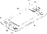
Fig. 1 is from the stereographic map from first half observation that is compatible with first tray salver of disc record and/or playback apparatus according to the present invention;
Fig. 2 is the stereographic map of first tray salver from Fig. 1 that Lower Half is observed;
Fig. 3 be according to of the present invention also can with the stereographic map of observing from the first half of second tray salver of disc record and/or playback apparatus compatibility;
Fig. 4 is the stereographic map of second tray salver from Fig. 3 that Lower Half is observed;
Fig. 5 is from the disc record of display screen direction observation and/or an embodiment stereographic map of playback apparatus according to the present invention;
Fig. 6 is from the disc record of tray salver fixator observation and/or the stereographic map of playback apparatus among Fig. 5;
Fig. 7 is the planimetric map that comprises the tray salver loader mechanism of the tray salver fixator that is included in disc record and/or the playback apparatus according to of the present invention;
Fig. 8 is the planimetric map that is inserted into first tray salver in the tray salver fixator;
Fig. 9 is the planimetric map that is engaged in the valve component supporting device on the valve component that is arranged on first tray salver;
Figure 10 is the planimetric map that is inserted into first tray salver in the tray salver fixator;
Figure 11 is the planimetric map of first tray salver that ejects from the tray salver fixator;
Figure 12 is the planimetric map that is inserted into second tray salver in the tray salver fixator;
Figure 13 is the planimetric map that partly inserts second tray salver in the tray salver fixator;
Figure 14 is the planimetric map that further is inserted into second tray salver in the tray salver fixator;
Figure 15 is the planimetric map that is inserted into second tray salver in the tray salver fixator; And
Figure 16 is the planimetric map of second tray salver that ejects from the tray salver fixator.
Embodiment
Below in conjunction with accompanying drawing disc record according to the present invention and/or playback apparatus are elaborated.
Be compatible with first tray salver according to disc record of the present invention and/or playback apparatus (after this being referred to as " disc record device/player "), this first tray salver comprises body, this body makes the disc-shape recoding medium such as CD rotatably be contained in it and has and is formed at writing and/or reading opening and making in it and writes and/or read that opening opens wide and closed valve component, and does not have any making and write and/or read that opening opens wide and second tray salver of closed valve component.
Before beginning to explain, need first and second tray salvers with disc record device/player compatibility be described according to disc record device/player of the present invention.
Consult Fig. 1 and Fig. 2 now, they schematically illustrate the tray salver of the first kind with the form of stereographic map.Always first tray salver by label 101 expressions is provided with valve component 102.As depicted in figs. 1 and 2, first tray salver 101 comprises the body of being made up of a pair of upward second body 103,104 of butt joint respectively 105.Tray salver body 105 has the CD 106 as disc-shape recoding medium that rotatably is contained in it.
Tray salver 101 holds (for example) wherein have program recorded thereon data and video data CD 106 to carry out video-game, and it is very little to be designed ground.This tray salver 101 can hold the small size that diameter for example is approximately the CD 106 of 60mm and is designed to be gripped by whole palm.
Notice that first tray salver of mentioning in conjunction with example 101 read-only in will being recorded in advance such as the information signal of routine data goes out CD 106 and be contained in wherein here.
As depicted in figs. 1 and 2, the tray salver body 105 of first tray salver 101 has circular arc front end 107, and tray salver 101 at first is inserted in disc record device/player there.The shape of this circular arc front end 107 is the center of the CD 106 in the disc accommodation section 108 that will be formed in the tray salver body 105 is a bit larger tham the radius of CD 106 as center and radius semicircles roughly.That is to say that circular arc front end 107 is corresponding with the CD 106 half-turn shapes in being contained in tray salver body 105.
Form relative side 109 parallel to each other and 110 respectively with the opposite end that circular arc front end 107 in the tray salver body 105 adjoins, and these sides 109,110 are adjacent to circular arc front surface 107 and slightly crooked rear surface 111 dorsad.That is to say, the rear surface 111 ratio of curvature semicircular arc front ends 107 of tray salver body 105 little, but radius ratio semicircular arc front end 107 is big.
As shown in Figure 2, the latter half 104 that constitutes the bottom of tray salver body 105 is formed with circular central opening 112 therein in the heart, be formed on the centre of the CD 106 that is contained in tray salver body 105 by this opening 112 center pit 106a, and its outer rim is exposed to the outside.A part (for example turntable) that is arranged on the disc rotary drive mechanism at the disc record device/player place of loading tray salver 101 is inserted into central opening 112.
As shown in Figure 2, the latter half 104 that constitutes tray salver body 105 bottoms also can form therein and write and/or read opening 113 (after this will be called " disc is near opening "), can be near CD so that information signal is write and/or reads from CD by its optical head.Disc is positioned near opening 113 on the side (109) of two sides (109,110) of tray salver body 105.Therefore it is formed rectangle, has enough sizes and is exposed to the outside with the part in the signal record zone that will be contained in the CD 106 in the tray salver 105 between internal diameter and external diameter.That is, disc near opening 113 along the straight and flat side 109 (rather than circular arc front end 107) of tray salver body 105 and form.In addition, by on a side 109, cutting the latter half 104 as shown in Figure 2 disc is opened wide near opening 113.
As depicted in figs. 1 and 2, first tray salver 101 is provided with dish is opened wide and closed valve component 115 near opening 113.Valve component 115 comprises: form the smooth valve component 116 of rectangle, this has smooth valve component 116 and makes the enough size of dish near opening 113 closures; And the supporting part 117 that also roughly has the C tee section that is formed on valve component 116 bottoms.
Can be provided with movably along the direction of the arrow A among Fig. 2, B valve component 115 with open wide and closure disc near opening 113, valve component 116 extends on coiling near opening 113, at 109 places, a side of tray salver 105, supporting part 117 is bearing on the part of the first half 103.
In addition, be formed with engaging hole 118 on the valve component 115, in this engaging hole 118, be engaged with the part of the valve component supporting device that is arranged on disc record device/player place, such as will be described.Engaging hole 118 is formed on the part of the supporting part 117 of a side 109 of tray salver body 105 dorsad.
Have, first tray salver 101 that is included among this embodiment is provided with valve component locking mechanism 119 again, when making disc near the position of opening 113 closures to move at valve component 115, and the moving of restriction valve component 115.Valve component locking mechanism 119 has the locking lever 121 that is bearing in pivotly on tray salver body 105 and the valve component 115.Locking lever 120 has the lock part 120 that is arranged on its free end, and the direction rotation of stressed effect around the pivot 120a that is arranged on the bottom along arrow C among Fig. 1, so that lock part 121 protrudes from the side 109 of tray salver body 105.When the direction of locking lever 120 arrow C in Fig. 1 pivots, lock part 121 is engaged on the engaging hole 118 that is formed in the valve component 115, and wherein valve component 115 has moved to and made disc near the position of opening 113 closures and therefore valve component 115 is locked in and makes the position of disc near opening 113 closures.
In valve component locking mechanism 119, when locking lever 120 overcome force-applying piece acting force and along with Fig. 1 in the side of arrow C pivot in the opposite direction, when threw off from engaging hole 118 its lock part 121, valve component 115 was disengaged locking and along disc is moved near the directions that opening 113 opens wide.
The tray salver 101 that is noted that the first kind that some is provided with valve component 115 has force-applying piece so that valve component 115 edges make disc move near the direction of opening 113 closures.
In addition, provide moving member gathering sill 122 in the side 109 of tray salver body 105, it is engaged in the valve component moving member that is arranged on disc record device/player place.Moving member gathering sill 122 is 109 formation along a side, to extend on the part of circular arc front end 107 as illustrated in fig. 1.
On tray salver body 105 another side 110 relative, be provided with and misplug into preventing groove 123, to prevent that first tray salver 101 is inserted into recorder/player upside down by mistake with the side 109 of supporting valve component 115.As shown in Figure 1, misplug into preventing that groove 123 from 110 forming and extend to the centre of side 107 along the another side always, thereby on the part of circular arc front end 107, extend.
If first tray salver 101 mistake is inserted into disc record device/player with being upside down, misplug into preventing groove 123, with restriction tray salver 101 being moved further in disc record device/player as mispluging into the valve component moving member insertion that prevents part and being engaged in.
Then, will describe second type tray salver of above-mentioned and of the present invention disc record device/player compatibility in conjunction with Fig. 3 and Fig. 4, it also can be compatible with first tray salver 101 with valve component 115.Second tray salver is always by label 201 expressions.
As first tray salver 101, be not provided with second tray salver 201 of valve component, comprise by a pair of upper and lower half body 103,104 and docking each other and the body 105 that forms, and as shown in Figure 3 and Figure 4 CD 26 rotatably is contained in it.
In addition in this tray salver 201, the latter half 104 as tray salver body 105 bottoms is formed with a circular central opening 112 in the central, be formed on CD 206 centers that are contained in the tray salver body 105 by this open centre hole 206a, and its outer rim is exposed to the outside, as shown in Figure 4.
As shown in Figure 4, also be formed with disc in the latter half 104 near opening 213, can be by its optical head near CD so that information signal is written to and/or reads from CD.Disc is similar near opening 213 on the disc that is formed in first tray salver 101 is positioned in tray salver body 105 like that near opening 113 the side (109) of two sides (109,110), and forms rectangle to extend to side 109 from the position near central opening 112.As shown in Figure 4, disc is open on the side 109 of tray salver body 105 equally near opening 213.
Because second tray salver 201 is not provided with any valve component, so it does not have the structure that groove in first tray salver 101 and so on is used to support valve component.
In second tray salver 201, be provided with moving member gathering sill 122 at 109 places, a side of tray salver body 105 in addition, it is meshing with each other with the valve component moving member that is arranged on disc record device/player.Moving member gathering sill 122 is envisaged as by preventing tray salver and be arranged on the mutual interference of the valve component moving member of the disc record device/player that can be compatible with first tray salver 101, thereby makes first tray salver 101 that valve component 115 is installed on it can be loaded onto in disc record device/player.
Be noted that in the time of in being loaded onto disc record device/player, it can not be subjected to any pressure effect from the valve component supporting device because second tray salver 201 does not have the valve component of close disc near opening 213, this will describe in detail in the back.
In addition, be formed with cavity 202 in second tray salver 201, when being loaded onto disc record device/player, be used for avoiding the pressure of valve component supporting device.That is, when second tray salver 201 is loaded onto in disc record device/player, the part of valve component supporting device will enter in the cavity shown in Figure 4 202.
In first tray salver 101, second tray salver 201 is provided with and misplugs into preventing groove 123 in 110 places, another side of a side 109 dorsad at tray salver body 105, with prevent second tray salver 201 with being upside down mistake be inserted in disc record device/player.
Then, will illustration and the disc record device/player of first and second tray salvers, 101,201 compatibilities of explanation and above-mentioned formation.
As shown in Figure 5 and Figure 6, always the disc record device/player by label 50 expressions comprises disk drives 51, wherein selectively loads first or second tray salver 101 or 201.Disk drives 51 comprise write and/or sensing element information signal is written to the CD 106 that is contained in first or second tray salver 101 or 201 or 206 or the information signal of playback record in CD 106 or 206.
As shown in Figure 5, disk drives 51 has display screen 52 to show view data and the character data from CD 106 or 206.
Disk drives 51 has the global operation of controller with control disk drives 51.Disk drives 51 controls write and/or sensing element and display screen 52.
Disk drives 51 comprises loader mechanism 1 (see figure 7), is used for first or second tray salver 101 or 201 is loaded into writing and/or reading unit.As the back described in detail, loader mechanism 1 comprised tray salver fixator 2, write and/or reading unit so that first or second tray salver 101 or 102 is fixed and is loaded into.Tray salver fixator 2 is supported on the bottom, thus insert or eject the position of first or second tray salver 101,201 and CD 101 or 102 is loaded into be arranged in the disk drives 51 write and/or the position of reading unit between move.
Disk drives 51 has the lid 53 of covering disk box fixing device 2.When tray salver fixator 2 be pivoted to first or second tray salver 101 or 201 can be loaded into write and/or reading unit in the position time, cover 53 covering disk box fixing devices 2 to cover disk drives 51.
Be noted that disk drives 51 is provided with ejector button (not shown) so that tray salver 101 or 102 is ejected from tray salver fixator 2.
Providing a plurality of on two the relative front sides across display screen 52 of disk drives 51 is used to carry out by the control knob 56,57 of writing and/or read the program of reading the unit and makes the operating key 58 that is presented at the picture roll on the display screen 52.
In addition, CD 51 is provided with write or read control knob and the power supply on/off button (not shown) that is used to control disc drive.
Below detailed description being arranged on being used in the aforementioned disc recorder/player is loaded into the mechanism of writing and/or reading the unit with first or second tray salver 101 or 201.
As shown in Figure 7, loader mechanism 1 comprises tray salver fixator 2, is used for that first or second tray salver 101 or 201 is held in place and will be contained in CD 106 or 206 in first or second tray salver 101 or 201 being loaded into and writing and/or read in the unit.Tray salver fixator 2 is set at bottom (not shown), which is provided with and writes and/or read the unit.Tray salver fixator 2 is supported in the bottom and goes up to insert or to eject the position of first or second tray salver 101 or 201 and CD 106 or 206 is loaded into and write and or read to move between the position in the unit.
As shown in Figure 7, valve component supporting member 6 has been mounted thrust piece 7 by the location, side of tray salver groove 3 and at free end, and its bottom is fixed on a side of tray salver fixator 2.Be noted that valve component supporting member 6 is installed in the outside of a side of tray salver fixator 2, this tray salver 2 has the thrust piece 7 that protrudes from tray salver 2.Since thrust piece 7 by be inserted in the tray salver fixator 2 the first or second tray salver fixator 101 or 201 the pushing, valve component supporting member 6 with the bottom of being fixed in tray salver fixator 2 be the center, along the direction elastic deformation that deviates from tray salver fixator 2 (direction of the arrow E among Fig. 7).
Here be noted that when first tray salver 101 is inserted into tray salver fixator 2, valve component supporting member 6 will be when inserting second tray salver 201 at least the shifting ground more severe.More particularly, when first tray salver 101 is inserted in the tray salver fixator 2, as the explanation of back, thrust piece 7 can be across on the valve component 115 that makes disc near opening 113 closures, and valve component supporting member 6 is more severe than shifting ground when inserting second tray salver 201 that does not have any valve component thus.
When first tray salver 101 was inserted in the tray salver fixator 2, valve component supporting member 6 can be across on the valve component 115 that is arranged at first tray salver 101 and therefore elastic deformation.Then, when first tray salver 101 is further inserted tray salver fixator 2, valve component supporting member 6 will flexibly return its initial position so that thrust piece 7 is engaged in the engaging hole 118 that is formed in the valve component 115 and supports valve component 115, limits valve component 115 thus and moves with respect to tray salver body 105.
In addition, when first tray salver 101 that is provided with valve component 115 is inserted into tray salver fixator 2, thrust piece 7 will push lock part 121 and be engaged in engaging hole 118 simultaneously with the twist-lock lever 120 in the opposite direction along the side of Fig. 1 arrow C, and therefore remove locking to valve component 115 to move with respect to tray salver body 105.
Be provided with valve component moving member 8 on a side of the tray salver fixator 2 that is provided with valve component supporting device 5, this valve component moving member 8 is engaged in the moving member gathering sill 122 that is formed at first or second tray salver 101 or 201.
Be noted that the thrust piece 7 than valve component supporting device 5, valve component moving member 8 is set at putting than deep-seated of tray salver fixator 2.
When first tray salver 101 was inserted in the tray salver fixator 2, valve component moving member 8 supported valve components and moves so that disc opens wide near opening 113 with respect to tray salver body 105.In addition, when first or second tray salver 101 or 102 is inserted into tray salver fixator 2 with being reversed, valve component moving member 8 will be engaged in and misplug into preventing that groove 123 is to prevent further first or second tray salver 101 or 102 to be inserted into tray salver 2.
Have, disc record/player according to the present invention comprises that dipper crowding gear 10 is inserted into second tray salver 201 in the tray salver fixator 2 with pushing again.Dipper crowding gear 10 is set on the another side relative with a side of installation valve component supporting device 5 tray salver fixator 2 on the tray salver fixator 2, on this side as shown in Figure 7.As shown in Figure 7, dipper crowding gear 10 comprises the pivot rotaring lever 12 that can support pivotally around pivot 11.Pivot rotaring lever 12 is provided with the thrust piece 13 that enters tray salver fixator 2 on the one end.
In addition, disc record device/player according to the present invention comprises pushing control gear 15, this mechanism 15 is according to being inserted into position that tray salver type in the tray salver fixator 2 controls dipper crowding gear 10 also, and nationality is inserted into the tray salver 101 of tray salver fixator 2 by dipper crowding gear 10 pushings or sheds by dipper crowding gear 10 applied pressures.
More particularly, pushing control gear 15 is connected in valve component supporting device 5.When first tray salver 101 was inserted into tray salver fixator 2, valve component supporting device 5 produced displacement to move the position that pushes control gear 15 and change dipper crowding gear 10 subsequently, sheds the pressure that is applied on first tray salver 101 thus.When second tray salver 201 was inserted into tray salver fixator 2,15 pairs of dipper crowding gears 10 of pushing control gear were controlled to promote second tray salver 201.
Above-mentioned pushing control gear 15 comprises control lever 16, and this control lever 16 is arranged on the tray salver fixator 2 and at the valve component supporting device 5 that is arranged on 2 one sides of tray salver fixator be arranged between the pushing member 10 of tray salver fixator 2 opposite sides.Control lever 16 is installed into a plurality of slide-and-guide bars 17 that will be arranged on the tray salver fixator 2 and is engaged in respectively in a plurality of long and narrow slide-and-guide holes 18, and moves between valve component supporting device 5 and dipper crowding gear 10.That is to say that control lever 16 is installed on the tray salver fixator 2, can move along the direction of arrow G among Fig. 7 and H.
One end of control lever 16 is formed with the control lever moving member 19 of the valve component supporting member 6 that is connected in valve component supporting device 5.To control an end bending of lever 16 and be overlapped on the free end of the valve component supporting member 6 that forms thrust piece 7, form control lever moving member 19 thus.
In addition, the other end of the pivot rotaring lever 12 of dipper crowding gear 10 is connected in the other end of control lever 16.Pivot rotaring lever 12 is equipped with connecting pin 20 at its other end, and this connecting pin 20 is engaged in the long and narrow connecting hole 21 of the other end of controlling lever 16.When control lever 16 when the direction of arrow G or H moves in Fig. 7, the pivot rotaring lever 12 that is connected in control lever 16 rotates along the direction of arrow K among Fig. 7 around pivot 11.
Be noted that control lever 16 is subjected to being arranged on tension spring 22 between control lever 16 and the tray salver fixator 2 along the effect of the direction of arrow H among Fig. 7, thereby make control lever moving member 19 near valve component supporting member 6.That is to say that control lever 16 is by the free end of pushing supporting valve component supporting member 6, so that thrust piece 7 protrudes in the tray salver fixator 2.
When the direction of arrow along Fig. 7 moved control lever 16, pivot rotaring lever 12 rotated along the direction of arrow L among Fig. 7 around pivot 11, so that thrust piece 13 is projecting inward from tray salver fixator 2.Therefore, pushing control gear 15 as mentioned above land deeds by pivot rotaring lever 12 pushing tray salvers 101 to insert it into tray salver fixator 2.
In addition, when first tray salver 101 is inserted into tray salver fixator 2 and valve component supporting member 6 direction of arrow E flexibly forms displacement in Fig. 7 because being arranged on the valve component 115 on the tray salver 101, control lever moving member 19 is by the pushing of the free end of valve component supporting member 6, and control lever 16 overcomes tension spring 22 and moves along the direction of arrow G among Fig. 7.When control lever 16 when the direction of arrow G moves in Fig. 7, the direction of pivot rotaring lever 12 around pivot 11 along arrow K among Fig. 7 rotated so that thrust piece 13 is deviate from tray salver fixator 2 is applied to first tray salver 101 that is inserted in tray salver fixator 2 with removal pressure.
As mentioned above, pushing control gear 15 is controlled dipper crowding gear 10 according to the shift length of valve component supporting device 5, thereby which kind of tray salver that detects in first or second tray salver 101 or 201 just is inserted into and is urged.More particularly, because when first tray salver 101 is inserted tray salver fixator 2, the shift length of valve component supporting device 5 is different from the situation of inserting second tray salver 201, therefore detecting in first (101) or second (201) tray salver which kind of is inserted in the tray salver fixator 2, that is, whether the tray salver of selecting just to be inserted in the tray salver fixator 2 will be urged.
As mentioned above, when first tray salver 101 is inserted tray salver fixator 2, the shift length of valve component supporting device 5 is different from the situation of inserting second tray salver 201, and the control lever 16 of pushing control gear 15 moves in corresponding to the distance of the shift length of valve component supporting device 5.Disc record device/player according to the present invention also comprises lever rod lock mechanism 25, is first or second tray salver according to the tray salver that is inserted in the tray salver fixator 2, and control lever 16 is locked in the position that control lever 16 has moved to.
Lever rod lock mechanism 25 comprises: sliding lever 26, and it is installed on disc fixator 2 and is pushing with first or second tray salver 101 that is inserted into tray salver fixator 2 and slide; And first and second engaging grooves 28,29, it selectively with the engagement flange 27 that is arranged at sliding lever 26 in an engagement.
Sliding lever 26 is installed on the tray salver fixator 2 movably.More particularly, be formed with a pair of long and narrow slide-and-guide hole 32 in the sliding lever 26, and be installed into can along first or second tray salver 101 or 201 to/move from the insertion/ejection direction of tray salver fixator 2, a pair of slide-and-guide bar 31 that wherein is arranged on tray salver fixator 2 is engaged in a pair of slide-and-guide hole 32 respectively.One end of sliding lever 26 is provided with thrust piece 33, and this thrust piece 35 is inserted into first or second tray salver 101 of tray salver fixator 2 or 201 at first inserting side pushing.Thrust piece 33 is formed and first or second tray salver 101 or 201 front ends, 107 corresponding circles, at this place first or second tray salver 101 or 201 at first be inserted in the tray salver fixator 2.The work that sliding lever 26 is subjected to being arranged on the tension spring 34 between sliding lever 26 and the tray salver fixator 2 in order to along and first or second tray salver 101 or 201 be inserted into the opposite ejection direction (direction of arrow M among Fig. 7) of the direction of tray salver 2 and move.
Part by cutting control lever 16 forms first and second engaging grooves 28,29 that are engaged in a flange 27.First and second engaging grooves 28,29 are formed on the moving direction perpendicular to the sliding bar 26 of control lever 16 moving directions.First engaging groove 28 is designed to down array structure: promptly when promoting thrust piece 7 by the valve component on first tray salver 101 that is inserted in tray salver fixator 2 115, valve component moving member 8 flexibly forms displacement along the direction of arrow E among Fig. 7, and control lever 16 moves along the direction of the arrow G among Fig. 7, and the engagement flange 27 on the sliding lever 26 will be in the face of open end.In addition, second engaging groove 29 is designed to down array structure: promptly when control lever 16 was in valve component moving member 8 and does not produce the initial position of elastic displacement, the engagement flange 27 on the sliding lever 26 will be in the face of open end.
The bottom that is noted that first and second engaging grooves 28 and 29 is formed on together as groove 30, will be engaged with engagement flange 27 in this groove 30.That is, first and second engagement flange 28,29 are separately as a branch of groove 30 and form.
When because be inserted into that first or second tray salver 101 or 201 in the tray salver fixator 2 slides and engagement flange 27 on the sliding lever 26 when engaging in first or second engaging groove 28,29 any one, control lever 16 is fixed on the position that has moved to because of valve component or is fixed on its initial position.
In addition, disc record device/player according to the present invention comprises that ejection lever 35 is to eject first or second tray salver 101 or 201 from tray salver 2.Ejection lever 35 is installed in can be on the bottom that pivot 36 pivots.When ejecting that lever 35 is inserted into first or second tray salver 101 of tray salver 2 or 201 pushings and when pivoting, be connected in the spring member that ejects lever 35 and therefore hold power, the power of being held is along the direction effect of ejecting first or second tray salver 101 or 102 from tray salver fixator 2.Ejecting lever 35 pivots under the effect of ejecting first or second tray salver 101 or 102 release forces from spring member from tray salver fixator 2.
Then will illustrate first or second tray salver 101 or 102 will be loaded into according to the process in the disc record device/player of said structure of the present invention.
At first, first tray salver 101 that is provided with valve component 115 is loaded into disc record device/player.
At first the circular arc front end 107 with first tray salver 101 is inserted into the tray salver fixator 2 from tray salver groove 3.
Because at first being inserted into the front end 107 of first tray salver 101 of tray salver fixator 2 is circular arc, thrust piece 7 will not contact first tray salver 101 as yet in the face of circular arc front end 107, and valve component supporting device 5 does not produce effect in the initial period of inserting tray salver 2.
As shown in Figure 8, when first tray salver 101 further was inserted into tray salver fixator 2 middle, thrust piece 7 can be on valve component 115, and flexibly produces displacement on the direction of valve component supporting member 6 arrow E in Fig. 8.Because the elastic displacement of valve component supporting member 6, control lever 16 will move along the direction of arrow G among Fig. 8.By control lever 16 moving along arrow G direction among Fig. 8, the pivot rotaring lever 12 of dipper crowding gear 10 rotates along the direction of arrow K among Fig. 8 around pivot 11, thereby thrust piece 13 is deviate from from tray salver fixator 2, and first tray salver 101 in being inserted into tray salver fixator 2 is not exerted pressure thus.
At this moment, sliding lever 26 makes its thrust piece 33 by circular arc front end 107 pushings of first tray salver 101, so that engagement flange 27 slides into towards the position of the open end of first engaging groove 28 that is formed on control lever 16, as shown in Figure 8.
As shown in Figure 9, when first tray salver 101 further was inserted in tray salver fixator 2, the thrust piece 7 that forms from valve component supporting member 6 was engaged in the engaging hole 118 that is formed on valve component 115.That is to say that thrust piece 7 is returned by the valve component supporting member 6 elastic reaction ground of big elastic displacement effect to its initial position across on valve component 115, thrust piece 7 is engaged to engaging hole 118 moving with restriction valve component 115.
Note being engaged under the situation of engaging hole 118 at thrust piece 7, first tray salver 101 still is applied in the pressure from valve component supporting member 6.That is, in this embodiment, when thrust piece 7 was engaged in engaging hole 118, valve component supporting member 6 formed elastic displacement slightly to support first tray salver 101 by the pushing effect.
When thrust piece 7 is inserted in the engaging hole 118, lock part 121 is promoted by thrust piece 7, locking lever 120 along with Fig. 1 in the side of arrow C pivot in the opposite direction to remove the locking of valve component 115 and valve component 115 can be moved with respect to tray salver body 105.
As shown in Figure 9, be inserted into tray salver 2 when being engaged in engaging hole 118 to thrust piece 7 since first tray salver 101, sliding lever 26 is also promoted to slide on direction of insertion and to make engagement flange 27 engage into first engaging groove 28 by first tray salver 101.Like this, get back to its initial position even valve component supporting member 6 is subjected to elastic reaction, control lever 16 is fixed on the position that is moved to by valve component supporting member 6.Because control lever 16 is fixed in along on the position that the direction of arrow G among Fig. 9 moves, and can limit and will be applied to from the pressure of dipper crowding gear 10 on first tray salver 101.
After thrust piece 7 is engaged in engaging hole 118, when first tray salver 101 further is inserted in tray salver 2, valve component moving member 8 enters the moving member gathering sill 122 that is formed in the tray salver 105, the valve component supporting device 115 that does not unlock with pressure support, as shown in figure 10.When first tray salver 101 further was inserted in tray salver 2, tray salver body 105 moved with respect to valve component 115, and first tray salver 101 is provided with in place in tray salver fixator 2 disc near opening 113 opens wide.
Because at this moment engagement flange 27 is engaged in first engaging groove 28, control lever 16 is fixed on the position that has been moved to by valve component supporting member 6, limits first tray salver 101 thus and is urged mechanism's 10 pushings.
In addition, because valve mechanism 115 is by the 8 pushing ground supportings of valve component supporting member, thrust piece 7 is engaged in the engaging hole 118 simultaneously, valve component 115 can't move freely, positively be held in place so that disc opens wide near opening 113, and first tray salver 101 that has a valve component supporting device 119 part 121 that is fixed remains on from the position that engaging hole 118 is thrown off.
When first tray salver 101 further is inserted in the position of tray salver fixator 2, eject lever 35 and rotate along the direction of arrow P among Figure 10 around pivot 36, and with eject the spring member that lever 35 links and correspondingly hold power.
For first tray salver 101 is ejected from tray salver fixator 2, the ejecting mechanism that is arranged on disc record device/player is actuated to discharge the power of savings in spring member so that eject the direction pivot of lever 35 along arrow Q among Figure 11.When the direction that ejects lever 35 arrow Q in Figure 11 pivoted, it pushed first tray salver 101.Therefore, first tray salver 101 will move along ejection direction from tray salver fixator 2.Because thrust piece 7 still is engaged in the engaging hole 118 this moment, valve component supporting device 115 is limited to move, have only tray salver body 105 to move along ejection direction from tray salver fixator 2 and also valve component 115 closed discs near opening 113, as shown in figure 11.
In addition, because first tray salver 101 is urged to the position of ejecting by ejection lever 35 from tray salver fixator 2 before, engagement flange 27 keeps being engaged in the state of first engaging groove 28, control lever 6 is fixed on the position that has moved to because of valve component supporting member 6, thereby the pressure that limits from dipper crowding gear 10 acts on first tray salver 101.
As shown in figure 11, in order to eject first tray salver 101 that has moved to ejected position from tray salver fixator 2, thrust piece 7 is thrown off from engaging hole 118 and on valve component 115, thereby makes the big displacement of valve component supporting member 6 formation.In addition, as shown in Figure 7, when first tray salver 101 was pulled out from tray salver fixator 2, thrust piece 7 left valve component 115 and makes valve component supporting member 6 be got back to its initial position by elastic reaction.Then, control lever 16 is also got back to its initial position under the effect of tension spring 22, protrude from tray salver fixator 2 at initial position thrust piece 13.In addition, the sliding lever 26 of lever rod lock mechanism 25 is got back to its initial position.
As mentioned above, when first tray salver 101 was inserted into tray salver fixator 2 according to disc record device/player of the present invention, dipper crowding gear 10 was controlled with not to first tray salver, 101 application of forces.Therefore, first tray salver 101 is subjected to from the pressure effect of valve component supporting device 5 and therefore is loaded onto in the tray salver fixator 2 as traditional disc record device/player.
Then, will be loaded into according to the process in the disc record device/player that as above constitutes of the present invention near second tray salver 201 of opening 213 with closed disc and describe not having valve component.
Similar with first tray salver 101, the circular arc front end 107 of second tray salver 201 at first is inserted into disc fixator 2 by tray salver groove 3.
Because at first being inserted into the front end 107 of second tray salver 201 of tray salver fixator 2 is circular arc, thrust piece 7 will not contact second tray salver 201 as yet in the face of circular arc front end 107, and valve component supporting device 5 does not produce effect in the initial period of inserting tray salver 2.
As shown in figure 12, owing to be that convenient second tray salver 201 has been inserted into and makes thrust piece 7 in the face of in the position of disc near opening 213, thrust piece 7 protrudes near opening 213 to disc, and valve component supporting member 6 does not produce elastic displacement ground and is not positioned at its initial position.
Notice that in the face of the thrust piece 7 of disc near opening 213 will be pushed, and therefore valve component supporting member 6 will not produce elastic displacement because disc in second tray salver 201 109 opens wide a side near opening 213.
Even thrust piece 7 is inserted into towards the position of disc near opening 213, wherein second tray salver 201 has been inserted in the tray salver fixator 2, also can not produce any pushing effect.Thus, valve component supporting member 6 will produce elastic displacement and be fixed on its initial position will control lever 16, rather than overcome tension spring 22 forced directions and move.Like this, under the effect of the power of the tension spring 22 that promotes control lever 16, the pivot rotaring lever 12 of dipper crowding gear 10 rotates along the direction of arrow L among Figure 14 around pivot 11, and thrust piece 13 protrudes a side pushing the latter with second tray salver 201 that will be inserted into tray salver fixator 2 in tray salver fixator 2.
As shown in figure 12, when second tray salver 201 be inserted into when thrust piece 7 towards disc during near the position of opening 213, thrust piece 33 is by circular arc front end 107 pushings of second tray salver 201, and circular arc front end 107 pushings that sliding lever 26 also has by second tray salver 201 make the engagement flange 27 of engagement flange 27 towards the position of the open end of second engaging groove 29 that is formed at control lever 16 to slide into.
Note when thrust piece 7 is faced disc near opening 213, second tray salver 201 in the present embodiment just is inserted in the tray salver fixator 2, when in a single day thrust piece 7 docked with a side 109 that is positioned at circular arc front end 107,7 of thrust pieces were faced disc near in the opening 213.At this moment, valve component supporting member 6 slightly forms elastic displacement, and control lever 16 overcomes the power of tension spring 22 and moves along the direction of arrow G among Figure 13.Yet, because controller lever 16 do not move to Be Controlled lever locking mechanism 25 locking, second tray salver 201 further be inserted into tray salver 2 and thrust piece 7 towards disc near opening 213.Then, the direction of thrust piece 7 arrow H in the Figure 12 of the effect lower edge of tension spring 22 moves and remains on its initial position.Therefore, pivot rotaring lever 12 rotates so that thrust piece 13 protrudes in tray salver fixator 2 along the arrow L direction among Figure 13 around pivot 11, thrust piece 13 towards a side of tray salver fixator 2 and promote, and makes second tray salver 201 remain on pressured state second tray salver 201 in the tray salver fixator 2.
Therefore as shown in figure 13, when second tray salver 201 further was inserted in the tray salver 2, it pushed sliding lever 26, and sliding lever moves and its engagement flange 27 is engaged in second engaging groove 29 along direction of insertion.Then, control lever 16 moves and is fixed on thus initial position by tension spring 22 along the direction of arrow H among Figure 14.
When second tray salver 201 begins further to be inserted into tray salver fixator 2 near the position of opening 213 from thrust piece 7 towards disc, thrust piece 7 moves from this position and on rear surface 111, because thrust piece 7 is by the pushing of the side 109 of tray salver body 105, valve component supporting member 6 pressurizeds and in Figure 14, produce elastic deformation shown in the arrow E on the direction.Control lever 16 is applied in to overcome tension spring 22 power and makes its acting force that moves along the direction of arrow G, but because the engagement flange 27 of sliding lever 26 is engaged in second engaging groove 29, it will get back to its initial position.
Elastic deformation by the valve component supporting member 6 on a side 109 that is caused across the thrust piece 7 on the rear surface 111 of tray salver body 105 will be absorbed by the distortion of valve component supporting member 6, and this distortion is produced by the gap between elastic component or the engagement flange 27 and second engaging groove 29.Therefore, even the power that overcomes tension spring 22 moves along the direction of arrow G, control lever 16 still is maintained at its initial position.
When second tray salver 201 further is inserted into tray salver fixator 2, as shown in figure 15, thrust piece 7 will enter and be formed on a cavity 202 on the side surface 109, and as shown in figure 14, and the valve component supporting member 6 that forms elastic displacement along the direction of arrow among Figure 14 is subjected to elastic reaction and returns.At this moment, second tray salver 201 is held on the throne in tray salver fixator 2.
At this moment, control lever 16 is subjected to tension spring 22 effect and moves along the direction of arrow H among Figure 11,15, thereby pivot rotaring lever 12 is rotated along the direction of arrow L among Figure 15 around pivot 11, therefore and thrust piece 13 is protruded from tray salver fixator 2, consequently thrust piece 13 promotes second tray salver 201 in the tray salver fixator 2 towards a side of tray salver fixator 2.
Like this, even when not having as first tray salver 101, to be inserted in disc record device/player by second tray salver 201 of the valve component 115 of valve component supporting device 5 pressure support, it is set in the tray salver fixator 2, simultaneously by dipper crowding gear 10 pushings.Like this, second tray salver 201 is urged and therefore is arranged on securely in the tray salver fixator 2, and this is the same with first tray salver 101 that provides valve component 115.
Note being inserted into when making thrust piece 7 enter into the position of cavity 202 when second tray salver 201, ejecting lever 35 rotates along the direction of arrow P among Figure 15 around pivot, the same with the situation of loading first tray salver 101, hold power and be connected in the spring member that ejects lever 35.
Note in order to reduce elastic deformation by the valve component supporting member 6 that is produced a side 109 across the thrust piece 7 on tray salver 105 rear surfaces 111, can thrust piece 7 across the position on form cavity.
For as shown in Figure 15 second tray salver 201 being ejected from tray salver fixator 2, operation setting, ejects lever 35 and pivots along the direction of arrow Q among Figure 16 thereby make discharging the power of savings in spring member at the ejecting mechanism of tray salver recorder/player.When the direction that ejects lever 35 arrow Q in Figure 16 pivoted, second tray salver 201 was by ejecting lever 35 pushings to move along releasing direction from tray salver fixator 2.
As shown in figure 16, by 35 pushings of ejection lever and before therefore the rear surface 111 of tray salver body 105 is moved to the position of ejecting from tray salver fixator 2, engagement flange 27 maintenances that are arranged on the sliding lever 26 are engaged in second engaging groove 29 at second tray salver 201.Because engagement flange 27 is engaged in second engaging groove 29, control lever 16 is held on initial position.In addition, because control lever 16 is in initial position, then by dipper crowding gear 10 pressure support second tray salver 201.Therefore second tray salver 201 is pushed, and is ejected lever 35 pushings to move to the pushing position until it, therefore can prevent that second tray salver 201 from being ejected suddenly from tray salver fixator 2.
By the rear surface 111 of holding tray salver body 105, the user can take out second tray salver 201 that moves to ejected position subsequently from tray salver fixator 2.
Illustrated as the front, no matter be inserted into second tray salver 201 that first tray salver 101 that tray salver in the tray salver fixator 2 provides valve component 115 does not still provide valve component 115, can will tray salver firmly be supported in the tray salver fixator 2 by valve component supporting device 5 or pushing member 10 respectively according to disc record device/player of the present invention.
In addition, be inserted into first or second tray salver 101 or 201 in the tray salver fixator 2 by valve component supporting device 5 or pushing member 10 pressure support respectively.Like this, no matter the tray salver that is inserted in the tray salver fixator 2 is first or second tray salver 101 or 201, it can both be applied in the pressure that gives about equally and therefore holding tray box fixing device 2 under stationary state.
In addition, in disc record device/player of the present invention, when first or second tray salver 101 or 201 is inserted in the tray salver fixator 2 with being upside down, valve component moving member 8 enters and is engaged in and is formed at mispluging into preventing groove 123 in the tray salver body 105.Therefore, can prevent that first or second tray salver 101 or 201 from being continued to be inserted in the tray salver fixator 2, can prevent from thus the tray salver mistake is inserted in the tray salver fixator 2.
In disc record device/player according to the present invention, when first tray salver 101 that provides valve component 115 was loaded, it was by valve component supporting device 5 pressure support.When second tray salver 201 without any valve component was inserted into, it was subjected to the pressure that is acted on by dipper crowding gear 10 and is supported.Therefore, the tray salver that is loaded in disc record device/player can positively remain in the tray salver fixator 2, no matter it is first or second tray salver 101 or 201.
In addition, first or second tray salver 101 or 201 that is loaded in disc record device/player is respectively by valve component supporting device 5 or 10 supportings of pushing member.Thus, no matter be first or second tray salver 101 or 102 can both be applied in the pressure that gives much at one and thus at the steady state (SS) lower support in tray salver fixator 2.
Note and be not limited to previous example, and can be any kind of tray salver that when being inserted into tray salver fixator 2, is not subjected to from any pressure effect of the valve component supporting device 5 that is arranged at disc record device/player place according to second tray salver 201 of disc record device of the present invention/player compatibility.Therefore, being used for tray salver according to disc record device/player of the present invention, to be not limited to those front ends that at first are inserted into disc record device/player be semicircular wherein any, and can be the rectangle front end.
Be appreciated that according to designing requirement and other all factor those skilled in that art can make multiple correction, combination, subitem combination and change, they all drop in the scope of claims and equivalent thereof.
Claims (9)
1. disc record and/or playback apparatus, comprise: the tray salver fixator, described tray salver fixator is used for fixing first tray salver of band body, rotatably accommodate disc-shape recoding medium in the described body, described body has and is formed in it and writes and/or read open side from being parallel to one that a side that first tray salver is inserted into a direction the equipment begins to extend to its center, by described opening, disc-shape recoding medium within it the footpath and external diameter between scope partly be exposed to the outside, first tray salver also has valve component, and described valve component is bearing on the tray salver body movably so that write and/or read the unlimited and closure of opening; Perhaps the tray salver fixator is used for fixing second tray salver of band body, rotatably accommodate disc-shape recoding medium in the described body, described body has and is formed in it and writes and/or read opening from being parallel to one that a side that tray salver is inserted into a direction the equipment begins to extend to its center, by described opening, disc-shape recoding medium within it the footpath and external diameter between scope partly be exposed to the outside;
The valve component supporting device, described valve component supporting device is inserted into the valve component of first tray salver in the tray salver fixator by pushing effect supporting, thereby limits moving of valve component;
Dipper crowding gear, described dipper crowding gear pushing is inserted into second tray salver in the tray salver fixator; And
Be connected in the pushing control gear of valve component supporting device, when first tray salver is inserted into the tray salver fixator, described pushing control gear moves because of the displacement of valve component supporting device, make the dipper crowding gear displacement, shed with the pressure that will put on first tray salver, and make dipper crowding gear push second tray salver that is inserted in the tray salver fixator.
2. equipment according to claim 1 is characterized in that described valve component supporting device can flexibly form displacement because being arranged on the valve component on first tray salver that is inserted in the tray salver fixator, thereby supports first tray salver by the pushing effect.
3. equipment according to claim 1 is characterized in that the valve component supporting device has the valve component supporting member of being made by resilient material, and described supporting member is by being inserted into the tray salver pushing in the tray salver fixator and flexibly producing displacement along the direction that deviates from tray salver.
4. as equipment as described in the claim 2, it is characterized in that the valve component supporting member can flexibly produce displacement and flexibly turn back to its original state on the valve component on being arranged at first tray salver that just is inserted in the tray salver fixator.
5. equipment according to claim 1 is characterized in that, described valve component supporting device and dipper crowding gear are positioned at respectively on one of the tray salver fixator and another side.
6. equipment according to claim 1, it is characterized in that, described pushing control gear has the shift length of corresponding valve component supporting device and the displacement that is controlled, the variation of described displacement depends on that the type of the tray salver that is inserted into the tray salver fixator is first or second tray salver, thereby control puts on the pressure of first or second tray salver that just is inserted into the tray salver fixator.
7. equipment according to claim 1, it is characterized in that, described pushing control gear has the shift length of corresponding valve component supporting device and the shift position that is controlled, the variation of described shift position depends on that the type of the tray salver that is inserted into the tray salver fixator is first or second tray salver, and described pushing control gear is fixed on the position that is moved to when first or second tray salver is inserted into the tray salver fixator.
8. equipment according to claim 1, it is characterized in that, described first tray salver comprises the valve locking mechanism, when described valve component is in when making on the position that writes and/or read the opening closure, be locked in that position in the engaging hole of described valve latch mechanism engages in being formed on valve component and with valve component, when first tray salver is inserted into the tray salver fixator, make the displacement of valve locking mechanism and from valve component, throw off by being engaged on valve component supporting device in the engaging hole that is formed in the valve component, make valve component move thus with respect to the tray salver body.
9. as equipment as described in the claim 2, it is characterized in that, also comprise and mispluging into limiting mechanism, when in case first or second tray salver is inserted in the tray salver fixator with being upside down by mistake, corresponding to make the valve component supporting device form displacement because being arranged on the valve component on first tray salver also owing to being engaged on the position that turns back to its initial position on the valve component, the described further insertion that misplugs into limiting mechanism restriction first or second tray salver.
Applications Claiming Priority (2)
| Application Number | Priority Date | Filing Date | Title |
|---|---|---|---|
| JP2004359013 | 2004-12-10 | ||
| JP2004359013A JP4207887B2 (en) | 2004-12-10 | 2004-12-10 | Disc recording and / or playback device |
Publications (2)
| Publication Number | Publication Date |
|---|---|
| CN1832011A true CN1832011A (en) | 2006-09-13 |
| CN100533579C CN100533579C (en) | 2009-08-26 |
Family
ID=36673117
Family Applications (1)
| Application Number | Title | Priority Date | Filing Date |
|---|---|---|---|
| CNB2005101370399A Expired - Fee Related CN100533579C (en) | 2004-12-10 | 2005-12-12 | Disc recording and/or playback apparatus |
Country Status (3)
| Country | Link |
|---|---|
| US (1) | US7475410B2 (en) |
| JP (1) | JP4207887B2 (en) |
| CN (1) | CN100533579C (en) |
Families Citing this family (6)
| Publication number | Priority date | Publication date | Assignee | Title |
|---|---|---|---|---|
| KR20100128958A (en) * | 2009-05-29 | 2010-12-08 | 엘지전자 주식회사 | Image display device and control method for the same |
| KR101598336B1 (en) * | 2009-05-29 | 2016-02-29 | 엘지전자 주식회사 | Operating a Remote Controller |
| US20100306688A1 (en) * | 2009-06-01 | 2010-12-02 | Cho Su Yeon | Image display device and operation method therefor |
| US8704958B2 (en) * | 2009-06-01 | 2014-04-22 | Lg Electronics Inc. | Image display device and operation method thereof |
| KR101572843B1 (en) * | 2009-06-03 | 2015-11-30 | 엘지전자 주식회사 | Image Display Device and Operating Method for the Same |
| JP6152687B2 (en) * | 2013-04-17 | 2017-06-28 | ソニー株式会社 | Disk transport device |
Family Cites Families (7)
| Publication number | Priority date | Publication date | Assignee | Title |
|---|---|---|---|---|
| JPH0817159A (en) * | 1994-06-29 | 1996-01-19 | Sony Corp | Disc cartridge |
| JPH0991824A (en) * | 1995-09-26 | 1997-04-04 | Sony Corp | Disk driving system |
| JPH09106605A (en) * | 1995-10-06 | 1997-04-22 | Sony Corp | Disc drive system |
| JP2003263819A (en) * | 2002-03-12 | 2003-09-19 | Hitachi Ltd | Optical disk drive |
| JP2005267826A (en) * | 2004-02-18 | 2005-09-29 | Sony Corp | Recording medium driving device, electronic device equipped with same, and recording medium cartridge |
| JPWO2005098857A1 (en) * | 2004-04-08 | 2008-03-06 | ソニー株式会社 | Disc cartridge and disc recording and / or reproducing apparatus using the disc cartridge |
| JP4168971B2 (en) * | 2004-05-10 | 2008-10-22 | ソニー株式会社 | Disc recording and / or playback device |
-
2004
- 2004-12-10 JP JP2004359013A patent/JP4207887B2/en not_active Expired - Fee Related
-
2005
- 2005-12-12 CN CNB2005101370399A patent/CN100533579C/en not_active Expired - Fee Related
- 2005-12-12 US US11/301,204 patent/US7475410B2/en not_active Expired - Fee Related
Also Published As
| Publication number | Publication date |
|---|---|
| US7475410B2 (en) | 2009-01-06 |
| CN100533579C (en) | 2009-08-26 |
| JP4207887B2 (en) | 2009-01-14 |
| JP2006172520A (en) | 2006-06-29 |
| US20060184955A1 (en) | 2006-08-17 |
Similar Documents
| Publication | Publication Date | Title |
|---|---|---|
| CN1171218C (en) | Cartridge disc | |
| CN1832011A (en) | Disc recording and/or playback apparatus | |
| CN1292437C (en) | Disk cartridge, forming member for disk cartridge, and method of manufacturing inner shell | |
| CN1169146C (en) | Disk container | |
| CN1249720C (en) | Cassette disk | |
| CN1211793C (en) | Disk drive unit | |
| CN1253889C (en) | Cartridge for containing recording medium | |
| CN1221181A (en) | Disc apparatus | |
| CN1251229C (en) | Cartridge for exchangeably containing a disc | |
| CN1855267A (en) | Disk drive device and electronic apparatus | |
| CN1253864C (en) | Shutter mechanism and disc driving device | |
| CN1542830A (en) | Disc cartridge | |
| CN1088236C (en) | Optical disc and disc cartridge | |
| CN1143295C (en) | Device for loading disk cartridge | |
| TWI344135B (en) | Optical disc device and method of controlling the same | |
| CN1224033C (en) | Disk drive unit | |
| CN1826654A (en) | Shutter member for disk cartridge, disk cartridge and disk recording and/or reproducing device | |
| CN1252691C (en) | Disc driver | |
| CN1229244A (en) | Recording and/or reproducing apparatus | |
| CN1860541A (en) | Disk drive apparatus | |
| CN1251216C (en) | Recording and/or reproducing appts. | |
| CN1658323A (en) | Magnetic storage device | |
| CN1867994A (en) | Disc cartridge assembly | |
| CN1076503C (en) | Disc playing equipment | |
| CN1701379A (en) | Disk cartridge |
Legal Events
| Date | Code | Title | Description |
|---|---|---|---|
| C06 | Publication | ||
| PB01 | Publication | ||
| C10 | Entry into substantive examination | ||
| SE01 | Entry into force of request for substantive examination | ||
| C14 | Grant of patent or utility model | ||
| GR01 | Patent grant | ||
| C17 | Cessation of patent right | ||
| CF01 | Termination of patent right due to non-payment of annual fee |
Granted publication date: 20090826 Termination date: 20100112 |