CN1076503C - Disc playing equipment - Google Patents
Disc playing equipment Download PDFInfo
- Publication number
- CN1076503C CN1076503C CN94107201A CN94107201A CN1076503C CN 1076503 C CN1076503 C CN 1076503C CN 94107201 A CN94107201 A CN 94107201A CN 94107201 A CN94107201 A CN 94107201A CN 1076503 C CN1076503 C CN 1076503C
- Authority
- CN
- China
- Prior art keywords
- disc
- turntable
- diameter
- lever
- opening
- Prior art date
- Legal status (The legal status is an assumption and is not a legal conclusion. Google has not performed a legal analysis and makes no representation as to the accuracy of the status listed.)
- Expired - Fee Related
Links
- 238000003780 insertion Methods 0.000 claims description 41
- 230000037431 insertion Effects 0.000 claims description 41
- 230000002093 peripheral effect Effects 0.000 claims description 19
- 230000007246 mechanism Effects 0.000 description 19
- 230000008878 coupling Effects 0.000 description 10
- 238000010168 coupling process Methods 0.000 description 10
- 238000005859 coupling reaction Methods 0.000 description 10
- 230000008859 change Effects 0.000 description 9
- 238000000034 method Methods 0.000 description 5
- 230000008569 process Effects 0.000 description 3
- 238000006073 displacement reaction Methods 0.000 description 2
- 238000000605 extraction Methods 0.000 description 2
- 238000009434 installation Methods 0.000 description 2
- 230000003287 optical effect Effects 0.000 description 2
- 230000009471 action Effects 0.000 description 1
- 230000002146 bilateral effect Effects 0.000 description 1
- 230000010485 coping Effects 0.000 description 1
- 238000001514 detection method Methods 0.000 description 1
- 230000007257 malfunction Effects 0.000 description 1
- 239000002184 metal Substances 0.000 description 1
- 229910052751 metal Inorganic materials 0.000 description 1
- 238000003672 processing method Methods 0.000 description 1
- GOLXNESZZPUPJE-UHFFFAOYSA-N spiromesifen Chemical compound CC1=CC(C)=CC(C)=C1C(C(O1)=O)=C(OC(=O)CC(C)(C)C)C11CCCC1 GOLXNESZZPUPJE-UHFFFAOYSA-N 0.000 description 1
Images


Classifications
-
- G—PHYSICS
- G11—INFORMATION STORAGE
- G11B—INFORMATION STORAGE BASED ON RELATIVE MOVEMENT BETWEEN RECORD CARRIER AND TRANSDUCER
- G11B17/00—Guiding record carriers not specifically of filamentary or web form, or of supports therefor
- G11B17/02—Details
- G11B17/04—Feeding or guiding single record carrier to or from transducer unit
- G11B17/05—Feeding or guiding single record carrier to or from transducer unit specially adapted for discs not contained within cartridges
- G11B17/051—Direct insertion, i.e. without external loading means
- G11B17/0515—Direct insertion, i.e. without external loading means adapted for discs of different sizes
-
- G—PHYSICS
- G11—INFORMATION STORAGE
- G11B—INFORMATION STORAGE BASED ON RELATIVE MOVEMENT BETWEEN RECORD CARRIER AND TRANSDUCER
- G11B19/00—Driving, starting, stopping record carriers not specifically of filamentary or web form, or of supports therefor; Control thereof; Control of operating function ; Driving both disc and head
- G11B19/02—Control of operating function, e.g. switching from recording to reproducing
- G11B19/12—Control of operating function, e.g. switching from recording to reproducing by sensing distinguishing features of or on records, e.g. diameter end mark
- G11B19/124—Control of operating function, e.g. switching from recording to reproducing by sensing distinguishing features of or on records, e.g. diameter end mark involving the detection of diameter of disks
Landscapes
- Feeding And Guiding Record Carriers (AREA)
Abstract
A disk playback apparatus comprises a loader holder, a loader movably disposed in the loader holder and having a disk slot, a pair of front levers symmetrically mounted on the front portion of the loader, and a pair of rear levers symmetrically mounted on the rear portion of the loader. When a compact disk is inserted into the loader through the disk slot so that a insert distance set in accordance with the diameter of the disk is exceeded, the front and rear levers cooperate with one another to push the loader into the loader holder while holding the inserted disk.
Description
The present invention relates to a Compact Disc (CD) player which can effectively transfer various record media with different disc diameters, such as Compact Discs (CD) with disc diameters of 12cm and 8cm, to the corresponding disc playing positions in the main body of the player.
Recently, disc player devices for optically playing back information recorded in a string of binary information on a disc-shaped recording medium (disc) have become popular. Among them, there are so-called Laser Discs (LD) having a disc diameter of 30cm, Compact Discs (CD) having disc diameters of 12cm and 8cm, and the like, and as a disc player, it is possible to play a disc corresponding to a different disc diameter, and therefore, many methods have been devised for starting the player.
In the top loading type (lid type) apparatus, different diameters of the turntable can be directly mounted on the turntable. In contrast, a tray which can be moved freely is provided between a disc playback position inside the apparatus main body and a disc insertion/removal position protruding outside the apparatus main body, and the disc is loaded on the tray and transported. In such a device, as reported in japanese unexamined patent application publication No. 5-121688, for example, a processing method for coping with different disc diameters is to form a plurality of stages by coaxially providing a plurality of circular concave portions on a tray surface in accordance with the disc diameter, and many attempts have been made to solve this problem.
A roller type apparatus has a large opening in the front of the apparatus body for inserting and removing a turntable disk, thereby inserting the turntable disk, and transporting the turntable disk to a turntable disk playback position by a roller provided in the apparatus body. As disclosed in japanese patent laid-open nos. 4-195855 and 5-298802, the roller-type device adjusts the position of a turntable by controlling the angle of opening of a pair of levers connected to the outer peripheral edge of the turntable inserted from the turntable insertion/removal port in accordance with the size of the diameter of the turntable.
The tray type device as described above is relatively simple in structure and is suitable as a disc player for a vehicle, and since such a disc player is often mounted in a narrow space near a driver's seat in a cab, there is a problem that it is not easy to take out the disc player from the device main body of the tray. The reel player of the roller type is adapted to be used as a disc player in a vehicle without the above-mentioned problems of the tray type because the disc is inserted into or ejected from the disc insertion/ejection opening provided in the front thereof.
However, the roller type apparatus is generally large in scale, and the fact that the structure is complicated cannot be denied. In the roller type apparatus, the loading operation is usually started by detecting a turntable when the front end of the turntable inserted from the turntable insertion/extraction opening reaches a predetermined position. For this reason, in the case of a turntable of 12cm turntable diameter, if half of the turntable is inserted, the loading operation can be started; however, in the case of a disc having a disc diameter of 8cm, the loading operation cannot be started unless the disc is almost completely inserted into the apparatus body. Further, there is a problem that the diameter of the turntable cannot be determined and the opening angle of the lever cannot be controlled without inserting the turntable to a certain depth.
Thus, such a turntable of 8cm diameter must be inserted deep, which seriously affects its operability and usability.
The present invention takes such a problem into consideration, and its object is: to provide a disc player which can accurately and efficiently load a plurality of discs having different disc diameters without using a tray, has excellent operability and usability, and has a simple structure.
The disc player of the present invention is provided with a 1 st control lever, a 2 nd control lever and a pressed portion for changing the connecting position of the 2 nd control lever.
The sliding plate is arranged between the disc playing position and the disc inserting and releasing position of the body and can move freely; the 1 st control lever is pressed by the peripheral edge of the turntable inserted into the sliding plate along the turntable surface, and moves to the changing position along the direction crossing the inserting direction of the turntable corresponding to the diameter of the inserted turntable; the 2 nd control lever changes the position connected with the sliding plate according to the position change of the 1 st control lever which moves the changing position corresponding to the size of the gramophone diameter, and one end is pressed by the peripheral edge of the gramophone disk inserted into the sliding plate, and then the control lever rotates by taking the position connected with the sliding plate as a fulcrum.
And a pressed part which is arranged on the body, when the sliding plate member is at the disc inserting and removing position, is engaged with the other end of the 2 nd control rod which rotates by taking the engaging position with the sliding plate member as a fulcrum, and limits the rotation of the second control rod so as to move the 2 nd control rod to the disc playing position side, wherein the pressed part corresponds to the engaging position of the 2 nd control rod and the sliding plate member which is set by changing the diameter of the disc.
On the slide plate, a drive means for moving the slide plate from the disc insertion/removal position to the disc playback position is activated when the slide plate moves to the disc playback position side due to the rotation of a 2 nd control lever connected to the pressed portion.
The 1 st control lever and the 2 nd control lever are symmetrically arranged in a pair in a direction perpendicular to the disc insertion direction, and elastically biased toward the center side of the slide plate to position the disc inserted into the slide plate at a predetermined position.
The 1 st control lever is provided with a connecting portion which is selectively connected to an edge portion of an opening provided in the body corresponding to the size of the disc diameter when the slider is positioned between the disc insertion/removal position and the disc playback position, thereby maintaining the posture of the 1 st control lever which is displaced in a manner corresponding to the disc diameter.
Further, at the connecting portion of the 1 st control lever, when the slider is pressed by the outer peripheral edge portion of the turntable inserted into the slider so as not to be displaced, it is connected to a part of the main body, and the slider is prohibited from being displaced from the turntable insertion/removal position to the turntable playback position side.
When the slide plate moves from the disc playing position to the disc inserting and removing position, the 2 nd control rod rotates reversely with one end connected with the pressed part and limiting the rotation as a fulcrum, and pushes the disc mounted on the slide plate out at the other end.
When the disc is inserted into the disc with respect to the slider, the 1 st lever is moved to a changed position corresponding to the size of the disc diameter, and the connection position between the 2 nd lever and the slider is changed accordingly, so that the pivot of the 2 nd lever, which is rotated by being pressed by the edge of the disc, is changed corresponding to the disc diameter. Then, the 2 nd lever is selectively connected to a pressed portion which is set in advance in the main body in accordance with the disc diameter, and is rotated while the rotation is restricted. By the rotation of the 2 nd control lever whose rotation is restricted, the slide plate is pressed to move to the disc playing position side, and the drive apparatus is started.
Thus, the pivot point and the pivot range of the 2 nd lever vary according to the disc diameter. The moving condition of the slider can be changed in a simple mechanical manner, and therefore, for the moving drive of the slider (the actuation of the turntable mechanism), the size of the disc to be inserted can be set to correspond to the size of the disc diameter, so that the good usability of the disc can be improved.
In addition, the 1 st control lever M and the 2 nd control lever U biased to the inner side can determine the position of the inserted turntable, and the loading position of the turntable can be accurately determined even though the diameter of the inserted turntable is different.
That is, the present invention provides a disc player, comprising: the sliding plate S is arranged between a disc playing position and a disc inserting and removing position which are supported on the guide plate G, can freely move and can move a disc (CD) arranged in the sliding plate S along the direction of a disc surface;
the 1 st control rod M is arranged at the sliding plate, can move freely, is pressed by the peripheral edge of a turntable disc inserted into the sliding plate along the turntable disc surface, and moves to the change position in the direction crossed with the insertion direction of the turntable disc corresponding to the diameter of the inserted turntable disc;
the 2 nd control lever U changes the position connected with the sliding plate according to the position change of the 1 st control lever which moves the changing position corresponding to the size of the disc diameter, and rotates with the connecting position with the sliding plate as a fulcrum after one end is pressed by the peripheral edge of the disc inserted into the sliding plate;
the push-out pressed part is arranged on the guide plate, corresponds to the connection position of the 2 nd control rod and the sliding plate which are set to change according to the change of the diameter of the turntable, and is connected with the other end of the 2 nd control rod which rotates after one end of the sliding plate is pressed due to the turntable when the sliding plate is positioned at the turntable insertion and extraction position, and restricts the rotation of the sliding plate, so that the 2 nd control rod is pressed at the turntable playing position.
Wherein, the said slide plate, after being connected with pressed part, and after being pressed with the junction of the 2 nd control rod that is pressed to the side of the playback position of the record, when moving to the side of the playback position of the record, make the slide plate insert and take off the drive unit that the position moved to the playback position of the record and start.
Wherein the 1 st control lever and the 2 nd control lever are symmetrically arranged in a pair in a direction perpendicular to the disc insertion direction, and elastically biased toward the center side of the slide plate to position the disc inserted into the slide plate at a predetermined position.
Wherein, in the direction forming a right angle with the direction of inserting the disc, there is a pair of 1 st control levers symmetrically, the 1 st control lever is biased to the central side of the slide plate elastically, the 1 st control lever has a interconnecting piece, when the slide plate is located between inserting and taking off position of the disc and disc position, it is according to the size of the diameter of the disc, it is connected with edge of the opening set up on the guide plate selectively, thus keep the posture of the 1 st control lever that the radial displacement of the corresponding disc shifts.
Wherein, in the direction forming a right angle with the direction of inserting the disc, there is a pair of 1 st control levers symmetrically, 1 st control lever is deflected to the central side of the slide elastically, 1 st control lever has a interconnecting piece, when receiving the pressing of the peripheral edge of the disc inserted into the slide and not producing the displacement, it is connected with a part of the guide plate, forbid the slide from inserting and taking off the position to the side of playback position of the disc.
Wherein, in the direction forming right angle with the direction of inserting the disc, there is a pair of 2 nd control levers symmetrically, 2 nd control lever bias to the central side of the slide plate elastically, when the slide plate is from the position of playing the disc to inserting and taking off the position of the disc, 2 nd control lever until one end that limit its rotation that is connected with pressing part is the fulcrum, the reverse rotation, push out the disc mounted on slide plate outside at its other end.
In summary, the present invention provides a disc player characterized in that it is provided with a body having first and second pressed portions, a slider member having an engaging portion for receiving a disc inserted from outside and for guiding the disc to move on the body to a disc playing position,
a driving device which is started when the sliding plate member starts moving and drives the sliding plate member to a predetermined position when the sliding plate member moves the disc to the disc playing position,
a 1 st control lever rotatably mounted on the slider member, pressing an outer peripheral edge of the turntable when the turntable is inserted into the slider member, and rotating only by an amount corresponding to a diameter of the turntable in a direction intersecting with an insertion direction of the turntable, and,
a 2 nd control lever having a body engagement portion and a slider member engagement portion, mounted on the slider member, and being interlocked with the 1 st control lever to press and rotate the outer periphery of the turntable platter inserted in the slider member,
when a small-diameter turntable is inserted into the slider member, the 2 nd control lever causes the body engaging portion thereof to contact the 1 st pressed portion and to rotate about the contact position as a fulcrum, and when a large-diameter turntable is inserted, the 2 nd control lever is linked with the 1 st control lever to cause the body engaging portion thereof to contact the 2 nd pressed portion and to rotate about the contact position as a fulcrum,
when the 2 nd control lever is rotated, the slider member is moved by the engagement of the slider member engagement portion with the engagement portion, and the driving device is started.
The 1 st and 2 nd control levers, the 1 st and 2 nd pressed portions, and the engaging portions are symmetrically arranged in pairs on the left and right sides of the insertion path, and elastic force in a direction to narrow the interval between the portions contacting the turntable is applied to each pair of the 1 st and 2 nd control levers by a spring.
The body has 1 st and 2 nd openings, and the 1 st lever has a guide projection which moves along the 1 st opening when the large-diameter disc is inserted and moves along the 2 nd opening when the small-diameter disc is inserted.
The body has a stopper portion connected to the 2 nd opening, and the movement relative to the slider member is prevented by engagement of the guide projection with the stopper portion in a state where the turntable is not inserted.
The following is further described with reference to the accompanying drawings. Wherein,
fig. 1 is a schematic perspective view of a disc player according to an embodiment of the present invention;
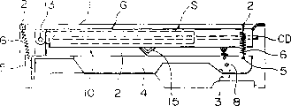
FIG. 2 is a side view of the internal structure of the device in the withdrawn state;
FIG. 3 is a side view of the internal structure of the same device in a sound reproducing state;
FIG. 4 is a plan view of the same device guide plate component configuration;
FIG. 5 is a cross-sectional view of a clamp configuration of the same device;
FIG. 6 is a plan view of the slide plate configuration of the same device;
FIG. 7 is an oblique view of the relationship between the 1 st control lever M and the 2 nd control lever U of the same device;
FIG. 8 is a plan view of the control lever M of the apparatus 1;
fig. 9 is a schematic view of the same apparatus in a state where a turntable is not inserted;
fig. 10 is a schematic view showing a state where a small-diameter turntable is inserted;
fig. 11 is a schematic view showing a state after the small-diameter disc is loaded;
fig. 12 is a state at the start of the insertion of the large-diameter turntable;
fig. 13 is a state of a large-diameter disc insertion process;
fig. 14 is a state after the insertion of the large-diameter disc is completed;
fig. 15 shows a state after the large-diameter turntable is loaded.
First, the overall structure of a disc player will be briefly described with reference to a practical example of the present invention.
FIG. 1 is a perspective view showing a schematic structure of the apparatus according to the embodiment, and FIGS. 2 and 3 are schematic side views showing an internal structure thereof. Fig. 2 shows a state when a disc is loaded, and fig. 3 shows a state when the disc is played.
The upper panel of the main body of the apparatus, the metal casing 1, shown in fig. 1 and 2 is bent downward at both sides and has a large opening at the side of inserting the turntable. A pair of spring mounting parts 2 for mounting springs are respectively arranged at the front and the rear of two sides of an upper plate of a case 1, and pin joint grooves 3 are respectively arranged in two side plates of the case 1. The phase box 1 is provided with a playback mechanism 4 in which a turntable and an optical head, not shown, are provided. The spring 6 is installed between the spring installation part 5 located at the front and the rear of the spring and the spring installation part 2 in the phase box 1, so that the playback mechanism 4 can move freely.
On the side of the playback mechanism 4, a pin 8 is provided which can engage with the pin-engaging recess 3. Above the playback mechanism 4, a drive element 10 is provided, which can be moved back and forth in the direction of insertion of the turntable by a motor, not shown in the figures. A coupling protrusion 11 coupled to a slider S (described later) is provided on the inner side of the drive member 10, and a cam surface 12 is formed at a disc insertion side portion coupled to the coupling protrusion 11.
A guide plate (body) G is arranged above the playback mechanism 4 and between the upper plate of the case 1. The guide plate G is connected to the playback mechanism 4 by a shaft 13 at the rear of the disc player, and is rotatable in the vertical direction. Further, on the disc insertion side, the guide plate G and the playback mechanism 4 are brought close to each other by the action of the spring 14. A protrusion 15 connected to the cam surface 12 is provided on the lower surface of the intermediate portion of the guide plate G, and the protrusion of the protrusion 15 faces downward.
The guide plate G has an I-shape on both sides thereof, and can guide and support the slide plate S inside thereof so as to be freely movable. The coupling protrusion 11 of the driving member 10 is in contact with a coupling recess 16 provided at the rear of the slide plate S, and the driving member 10 and the slide plate S are integrally moved. The guide plate G and the slide plate S will be described in detail later.
However, if a CD player is inserted into the slider S, the slider S is moved slightly toward the inside of the disc player, and this movement is detected by a photoelectric sensor and a detection means (not shown) such as a leaf-shaped stitch, and a motor (not shown) is activated to move the driving member 10 inward. In this way, since the coupling protrusion 11 of the coupling driving member 10 is coupled to the slide plate S, the slide plate S is moved to a disc reproduction position in the disc reproducing apparatus. At this time, the disc loaded on the slide S is loaded to the reproducing position.
When the slide plate S is in the state shown in FIG. 2, i.e., at the retreating position, the cam surface 12 of the driving member 10 comes into contact with the projection 15 of the guide G, so that the spring 14 between the playback mechanism 4 and the guide G is elongated and they are separated from each other at the leading end on the disc inserting side. Thus, the guide rail G is connected with the upper plate of the case 1, and the pin 8 on the playback mechanism 4 is connected with the pin connection groove 3 of the case 1.
When the slide plate S is transferred from the above state to the disc reproduction position at the rear of the apparatus shown in FIG. 3, since the inclined surface of the cam surface 12 of the driving member 10 has reached the position of the projection 15 of the guide plate G, the reproduction mechanism 4 and the guide plate G are brought close to each other by the spring 14. Thus, the guide plate G pushed up is separated from the upper plate of the cabinet 1 by the playback mechanism 4, and then the connection pin 8 of the playback mechanism 4 is separated from the pin-joint groove 3 of the cabinet 1. Further, the playback mechanism 4 is integrally formed with the guide plate G, and is elastically supported on the inside of the cabinet 1 by a spring 6. At this time, since the playback mechanism 4 is adjacent to the guide plate G, the disk placed on the slide plate S is fixed by being mounted on the turntable, and is played back by the optical head.
As means for moving the slide plate S to the record playing position, a method of moving the disc tray is also possible as described in japanese unexamined patent application publication No. 5-128688 and the like.
The guide plate G has a structure (shape) symmetrical right and left as shown in fig. 4, and a slide plate S is mounted on the inner side of the guide plate G. The left half of fig. 4 shows a state in which a large-diameter disc is inserted into the slide plate S, and the right half shows a state in which a small-diameter disc is inserted into the slide plate S. The state of the disc inserted here is a state in which only the disc is inserted into the slider and no force is applied from the outside.
The front end 21 of the guide plate G is a curved surface that rises at one step as shown in fig. 1. Further, 6 openings in total of 3 pairs of openings 22, 23, 24 are formed on the upper surface of the guide plate G facing the inside from the front end portion 21 thereof.
Inside the outermost large-diameter turntable opening 22, there is a larger opening 26. This opening 26 is on the turntable insertion side, and has a pressed portion 27 for the large-diameter turntable; at the innermost side of the opening 26, a pressed portion 28 for a small-diameter turntable is provided, and the pressed portion 28 is formed in a recessed shape. Further, a connection portion 30 for a small-diameter disc and a connection portion 31 for a large-diameter disc are provided on the back side of the opening 26. The pressed portions 26 and 27 and the connecting portions 30 and 31 are provided so as to be movable in the lateral direction of the guide plate G in accordance with the size of the diameter of the disc inserted into the slide plate S. These functions will be described later.
Further, the 2 nd opening 23 for the small-diameter disc from the outside is inclined slightly inward toward the back surface, and a catch recess 23a is provided at the disc insertion side tip. The guide projection opening 24 on the innermost side is straight in the disc insertion direction. The guide plate G has an opening 33 for the clamper at the center, a spring 35 for pressing the clamper at the back, and the spring 35 is fixed by a nut 36, and functions of these openings 23 and 24 will be described later.
The freely movable slide plate S provided inside the guide plate G will be described below. Fig. 6 is a plan view showing a configuration of half portions of the slide board S having a bilaterally symmetrical structure. Fig. 7 is a perspective view showing a connection relationship between the 1 st control lever M and the 2 nd control lever U mounted on the slide plate S, and fig. 8 is a view showing an operation configuration of the 1 st control lever M.
The slider S has a large-opening flat box-like structure on the side where the turntable is inserted, and has openings for chucking and the like in the upper and lower plates. On the upper plate of the slide plate S, a pair of the 1 st control lever M and the 2 nd control lever U are respectively arranged in bilateral symmetry.
The 1 st lever M is composed of a vertically downward disc support portion 41 at the front end of the disc insertion side and a protrusion 42 beside the inner side thereof. The protrusion 42 selects one of the opening 22 for the large-diameter disc and the opening 23 for the small-diameter disc, and is connected thereto so that the guide function protrusion 42 protrudes upward. As shown in fig. 6, the pivot shaft 43 of the 1 st lever M is rotatably attached to a projecting shaft attachment portion 44 of the upper plate portion of the slide plate S. Further, a portion of the turntable entrance side from the rotational shaft 43 of the 1 st lever M moves within a region 45 as shown in FIG. 6, and the region 45 is lower than the 1 st lever M from the upper plate surface of the upper plate of the slide plate S by only the thickness of the 1 st lever M.
As shown in fig. 7, a spring mounting portion 47 is formed at a position inside the pivot shaft 43 of the 1 st lever M. The spring mounting portion 47 is connected to the tip ends of wire springs 51 fixed to spring fixing portions 49 and 50 on the slide plate S. Due to the wire spring 51, the 1 st lever M and the front end side of the turntable support portion 41 formed thereon rotate inward in opposite directions, changing positions being close to each other.
Further, the outer side of the rotating shaft 43 located at the distal end of the 1 st control lever M has a curved groove 53 as shown in FIGS. 7 and 8. The groove 53 is composed of 53a, 53b and 53 c. The end of this groove 53 on the disc insertion side is an arc 53a having a radius a and centered on the rotational axis 43; similarly, the inner end is an arc section 53c having a radius B larger than the radius a and having the rotation axis 43 as a center; in the middle is 53b of the smooth connection 53a, 53 c.
In the groove 53, a pivot shaft 55 of the 2 nd lever U is inserted, and the pivot shaft 55 protrudes from both the inside and outside surfaces of the 2 nd lever U. As shown in fig. 6 and 8, the inner rotary shaft 55 is connected to an opening 56 of the slider S, and under the restriction thereof, the sliding position can be determined according to the size of the disc diameter. Further, when the 1 st lever M is in the position shown by the solid line in FIG. 8, i.e., when the small-diameter turntable is inserted, the rotational shaft 55 is guided to the outside of the opening 56 from the inner tip of the groove 53. When the 1 st lever M is rotated from the position indicated by the solid line to the position indicated by the two-dot chain line, the groove 53 connected to the rotating shaft 55 is also moved along with the rotation, and the intermediate portion 53b presses the rotating shaft 55 to move to the position inside the opening 56. Therefore, when the 1 st lever M is at the position of the two-dot chain line, i.e., when the large-diameter turntable is inserted, the rotational shaft 55 is moved to the inner side position of the opening 56. Thus, the 1 st lever M serves to detect the size of the turntable diameter by changing the position of the rotational shaft 55 of the 2 nd lever U according to the size of the turntable diameter inserted into the slide plate S.
The area 58 of the 2 nd control lever U on the upper plate of the slide S is lower than the area of the 1 st control lever M by the thickness of the 2 nd control lever U as shown in FIG. 6. Thus, the area 45 and the area 58 are sequentially lowered with respect to the plate surface of the slide plate S. Thus, the 1 st control lever M and the 2 nd control lever U are all collectively mounted within the range of the thickness of the slide plate S.
At the inner tip of the 2 nd lever U, as shown in FIG. 7, a vertically downward disc support portion 61 is provided, which is the same as the disc support portion 41 of the 1 st lever M. These disc support portions 41 and 61, as shown in fig. 6 and 7, protrude from the inner side of the slide plate S through an opening 62 provided at the upper plate of the slide plate S, contact the outer peripheral edge of the disc inserted into the slide plate S, change positions inward, and serve to support the disc. At the outer tip of the 2 nd control lever U, there is a projecting pin 64 facing upward, as shown in FIG. 4, projecting from the opening 26 of the guide plate G.
The 2 nd lever U is pivoted to the rotational shaft 55 by a spring 66 connected to the spring mounting portion 65, and the turntable supporting portion 61 is pivoted inward. The spring 66 is installed at the fixing portion 67 of the slide plate S. Further, in the disc ejecting state (the state in which the disc is not inserted), the 2 nd control lever U is rotated until the disc support portion 61 comes into contact with the insertion side end face 68 of the opening 62.
An annular portion 71 for a clamper 70 is provided at a portion of the upper disc insertion side of the slide plate S. The clamper 70 provided in the ring portion 71 moves together with the slide plate S. When the slide plate S is moved to the disc playback position, the clamper 70 is positioned above the turntable 17 facing the playback mechanism 4. Then, the clamper 70 is pressed downward in contact with the pressing spring 35 pressing the clamper 70, the turntable is mounted on the turntable, and when the turntable is lifted up in the slide plate S, the upper surface of the turntable is pressed, and the turntable is chucked in a non-contact state with the slide plate S.
On both sides of the ring portion 71, 4 projections 72 (2 on the left side are shown) for preventing the clamper 70 from falling off are projected upward. These projections 72 are guided by the projection openings 24 for guiding of the guide plate G shown in fig. 4.
The operation of the example apparatus configured as described above will be described below.
Fig. 9 shows a state before the disc is inserted, fig. 10 shows a state when the small-diameter disc is inserted, and fig. 11 shows a state when the small-diameter disc is transferred to a disc playback position.
The state of the disc when the disc is inserted is shown in fig. 9. The 1 st lever M is rotated counterclockwise by the elastic force of the wire spring 51, and the projection 42 thereof is located at the catch recess 23a provided at the front end of the opening 23 for the small-diameter turntable. At this time, the turning shaft 55 of the 2 nd lever U is pressed at the inner side 53c of the recess 53 at the outer side end of the opening 56. As shown in fig. 9, the pin 64 of the 2 nd lever U is in contact with the pressed portion 28 for the small-diameter disc of the guide plate G. Further, the 2 nd lever U is rotated clockwise as shown in the drawing by the spring 66 about the rotational shaft 55, so that the base of the record supporting portion 61 is brought into contact with the turntable insertion side end face 68 of the opening 62 of the slide plate S.
When the small-diameter disc is inserted into the slide plate S as shown in fig. 9, the disc support portion 41 of the 1 st lever M contacts the outer peripheral edge portion of the disc and is pushed outward, and the 1 st lever M moves against the elastic force of the wire spring 51 as shown in fig. 10. In this case, the 1 st lever M is rotated in a range in which the projection 42 is disengaged from the catch recess 23a due to the small diameter of the turntable. To a position where it can be connected to the opening 23 for the small-diameter turntable. In addition, in this state, the rotation shaft 55 of the 2 nd control lever U is maintained in a state of being connected to the inner side 53c of the recess 53 of the 1 st control lever M. Therefore, as shown in fig. 8, the rotation shaft 55 cannot be removed from the outside of the opening 56.
In this state, when the small-diameter disc is further inserted inward, the outer peripheral edge of the disc is connected to the disc support portion 61 of the 2 nd lever U in the inside thereof, resulting in the state shown in fig. 10.
From the state of fig. 10, the small-diameter disc is pushed inward, the disc is pressed, and the disc support portion 61 is moved inward. The 2 nd control lever U rotates counterclockwise around the rotation shaft 55. When the 2 nd lever U rotates about the rotation shaft 55, the pin 64 of the 2 nd lever is engaged with the pressed portion 28 for a small-diameter turntable on the guide plate G, and the rotation is restricted. Thus, the pin 64 which is restricted from rotating after coming into contact with the pressed portion 28 for a small-diameter disc becomes a rotation fulcrum of the 2 nd lever U, and the rotation shaft 55 moves the slide plate S to the back side of the guide plate G through the connection opening 56 of the slide plate S, that is, moves the disc in the direction of the playback position.
The slider S moves with the rotation of the 2 nd lever U so that the disc insertion is detected, and the motor is started to move the slider S by the movement of the driving part 10 so that it is drawn to the inside of the guide plate G. When the slide plate S is pushed in, the projection 42 of the 1 st lever M is guided through the small-diameter disc opening 23, and slightly moves inward to change the position. Due to the shift toward the inner side of the 1 st lever M, the small-diameter disc is fed to the back side of the slide plate S, and the center position is determined for the clamper 70, resulting in the state shown in FIG. 11.
When the slide plate S is pushed to the end, the pin 64 is engaged with the small-diameter turntable coupling 30, and the 2 nd control lever U is slightly rotated counterclockwise. Due to the rotation of the 2 nd control lever U, the turntable supporting portion 61 is separated from the peripheral edge portion of the turntable and retreated to the outside, and the fixing and rotation of the turntable mounted on the turntable are not affected when the audio is played at the audio playback position of the turntable.
On the other hand, the disc is ejected from the minor-diameter disc playback position by the reverse rotation of the drive unit 10, which drives the slide plate S to move from the disc playback position to the ejection position. At this time, the pin 64 of the 2 nd lever U is first disengaged from the small-diameter turntable coupling portion 30 of the guide plate G by the movement of the slide plate S, so that the 2 nd lever U is rotated clockwise by the force of the spring 66, and the turntable supporting portion 61 comes into contact with the outer peripheral edge of the small-diameter turntable to support the turntable. As a result, the small-diameter disc moves toward the disc insertion position side together with the slider S.
With the movement of the slide plate S, the pin 64 of the 2 nd control lever U is engaged with the pressed portion 28 for the small-diameter disc, and the movement thereof is restricted. In this state, the slide plate S continues to move, and the 2 nd control lever U pivots on the pin 64 connected to the pressed portion 28 for the small diameter disc. The rotation of the 2 nd control lever U causes the small-diameter disc to be pressed by the disc support 61 and pushed out in front. As a result, the small-diameter disc is ejected from the disc insertion port until the protruding portion becomes half of the disc as shown in fig. 10.
In contrast, if a large-diameter disc is loaded into the disc player, the operation is performed as follows. Fig. 12 shows a state when the insertion of the large-diameter disc is started, and fig. 13 shows a state when the insertion of the large-diameter disc is completed. Fig. 14 shows a state where the disc is pushed further inward from the state where the disc is inserted, and fig. 15 shows a state where the disc is transferred to the playback position.
When the turntable is not inserted, as shown in fig. 9, the projection 42 of the 1 st lever M is located in the engagement recess 23a of the small-diameter turntable opening 23, and the rotational shaft 55 of the 2 nd lever U is located at the outer end of the opening 56. The pin 64 of the 2 nd lever U is engaged with the pressed portion 28 of the guide plate G for the small-diameter disc.
In this state, the large-diameter turntable is inserted, the turntable support portion 41 at the tip of the 1 st lever M is connected to and pressed against the outer peripheral edge of the large-diameter turntable, and is rotated clockwise in the drawing about the rotation shaft 43 against the elastic force of the wire spring 51, and as shown in fig. 12, the change in the outer position is large, and the rotation of the 1 st lever M causes the rotation shaft 55 connected to the groove 53 to be pressed by the turntable insertion side end portion 53a of the groove 53, and to move from the outer side of the opening 56 to the inner side. Since the 1 st lever M is rotated outward, the projection 42 is disengaged from the catch recess 23a and moved to a position where it can be engaged with the opening 22 for the large-diameter turntable.
As the 1 st control lever M is rotated, the rotation shaft 55 of the 2 nd control lever U moves inward, and the entire 2 nd control lever U also moves inward. Then, as the 2 nd lever U moves, the pin 64 provided therein comes out of the connection position of the small-diameter disc pressed portion 28 and moves inward, thereby forming a state shown in fig. 12.
In this state, if the large-diameter disc is further inserted inward, the inner side of the inserted large-diameter disc is connected to the disc support portion 61 of the 2 nd lever U, and is pressed to rotate. At this time, since the pin 64 is disengaged from the connection position of the pressed portion 28 for the small-diameter turntable, the 2 nd control lever U is rotated counterclockwise in the drawing about the rotation shaft 55 in accordance with the insertion of the large-diameter turntable, and this rotation of the 2 nd control lever U is performed against the elastic force of the spring 66.
However, as the 2 nd control lever U rotates, when the pin 64 thereof comes into contact with the large-diameter disc pressed portion 27 as shown in fig. 13, the rotation of the 2 nd control lever U about the rotation shaft 55 is restricted by the large-diameter disc pressed portion 27.
When the large-diameter disc is further pushed inward in the state shown in fig. 13, the edge of the large-diameter disc is pressed, and the disc support 61 moves inward. The 2 nd control lever U rotates counterclockwise about the rotation shaft 55. However, at this time, the pin 64 of the 2 nd lever U contacts the pressed portion 27 of the guide plate G for the large-diameter turntable, and the rotation thereof is restricted. Therefore, the 2 nd control lever U pivots about the connecting portion between the large-diameter disc pressed portion 27 and the pin 64. Thus, the opening 56 is brought into contact with the pivot shaft 55 of the 2 nd control lever U, and as shown in fig. 14, the slide plate S is displaced by the pivot shaft 55 of the 2 nd control lever U, and the slide plate S moves inward.
As the slider S moves, a disc inserted into the slider S is detected, and the motor is started to move the driving unit 10. Due to the movement of the driving member 10, the slide plate S enters the inside of the guide plate G as shown in fig. 15. At this time, the projection 42 of the 1 st lever M is connected to the large-diameter disc opening 22 and moves into the disc player. The opening 22 for the large-diameter turntable serves as a guide for the protrusion 42, so that the position of the 1 st lever M is maintained. The large diameter disc is transferred to a disc playing portion inside the guide plate G together with the slide plate S supported on the 1 st lever M.
When the large-diameter disc is pushed to the disc-playing position, the pin 64 is engaged with the large-diameter disc-use coupling portion 31, and the 2 nd control lever U is further rotated counterclockwise. As a result of the rotation of the 2 nd control lever U, the turntable support 61 is separated from the outer peripheral edge of the large-diameter turntable so as not to interfere with the fixing and rotation of the turntable during the playback of the turntable.
The ejection process of the large-diameter disc loaded on the disc player as described above is performed as follows.
When the eject operation is performed, the drive member 10 moves in the reverse direction, and the pin 64 is disengaged from the large-diameter disc coupling portion 31 in accordance with the movement of the slider S, and the 2 nd lever U is turned inward by the spring 66. The rotation of the 2 nd lever U causes the turntable supporting portion 61 of the 2 nd lever U to contact the outer peripheral edge of the large-diameter turntable and to support the large-diameter turntable together with the turntable supporting portion 41 of the 1 st lever M.
In this state, the slide plate S moves toward the disc inserting position as a whole with the 1 st and 2 nd control levers M and U. When the slide plate S reaches the disc insertion position, the pin 64 of the 2 nd lever U abuts on the large-diameter disc pressed portion 27 to restrict the movement thereof, and thereby the 2 nd lever U is further rotated inward. Due to the rotation of the 2 nd lever, the large-diameter disc is pressed by the disc support portion 61 of the 2 nd lever U to be partially pushed out in front of the apparatus, and the disc is ejected, resulting in the state shown in fig. 13.
Thus, when the large-diameter disc is inserted into the disc insertion opening with the disc protruding from the disc insertion opening, and the disc is removed by holding the large-diameter disc protruding portion with a hand, the 1 st lever M is urged by the spring 51 to rotate inward, and returns to the initial state shown in fig. 9.
The constitution of the example apparatus and the operation thereof were explained above.
Here, the features of the device of this embodiment are summarized. The slide plate S is provided between the disc playback position and the disc insertion position, and is supported by the guide plate G so as to be freely movable. The 1 st lever M can be modified in rotation angle according to the size of the turntable platter diameter into which the slider S is inserted, and can be rotated about the rotation shaft 43 as a fulcrum. Meanwhile, a 2 nd lever U is provided, which is connected to the 1 st lever M and changes the position of the pivot (position of the rotary shaft 55) according to the rotation angle of the 1 st lever M, that is, according to the size of the diameter of the inserted disc. At one end of the 1 st lever M, a turntable supporting portion 41 is provided, and at one end of the 2 nd lever U, a turntable supporting portion 61 is provided for supporting a peripheral edge portion of a turntable inserted in the slide plate S. This is one of the features.
The guide plate G has pressed portions 26, 27 which are selectively connected to a pin 64 at the other end of the 2 nd lever U according to the size of the turntable diameter to change the pivot point thereof, and the range of the rotation is restricted. Further, they move the rotating shaft 55 body of the 2 nd lever U to the disc playback position in accordance with the rotation of the 2 nd lever U when the 2 nd lever U is rotated. This is yet another feature thereof. In this way, the pin 64 is selectively connected to the pressed portions 26 and 27, so that the 2 nd lever U is moved to move the slide plate S to the position, and the loading mechanism is activated to move the driving member 10 to move the slide plate S to the sound-emitting position.
The apparatus having the above-described structure can control the opening angle (rotation angle) of the 1 st lever M and the rotation point of the 2 nd lever U, and the rotation angle thereof, according to the size of the diameter of the disc inserted into the slider. Therefore, even if the sizes of the discs are different, the outer peripheral edge portion of the disc can be reliably supported, the disc can be inserted to a designated position in the slide plate S, and the disc can be transferred to the disc playing position.
Further, the position of the pivot point of the 2 nd lever U (the position corresponding to the pivot shaft 55 of the slider S) can be changed according to the size of the inserted turntable diameter, and the position (the pressed portions 26 and 27) for restricting the pivoting of the 2 nd lever U can be changed, so that the slider S starts moving according to the turntable diameter in accordance with the amount of insertion of the turntable. Therefore, the loading mechanism can be operated without being limited by the size of the turntable disc diameter, and the processing capacity of the turntable disc can be improved by inserting the turntable disc approximately half way. In addition, at the time of the eject operation, the turntable can be pushed out by the rotation of the 2 nd control lever U in which the position of the rotation fulcrum is changed, corresponding to the turntable diameter. Therefore, even if the disc is a small-diameter disc, the disc can be sent out by about half and is easy to take out. Thus, the usability of the turntable is further improved.
When the turntable is not inserted, the 1 st lever M is biased inward by the force of the spring 51, and the pin 42 provided in the 1 st lever M is positioned to face the engaging recess 23 a. Therefore, in this state, the pin 42 is connected to the engagement recess 23a, and the 1 st lever M is prevented from moving inward. I.e., to prevent the slide plate S from moving to the disc playing position side. Therefore, when the turntable is inserted, the 1 st lever M does not rotate outward, the loading mechanism does not operate, and malfunction can be prevented.
When the slide plate S moves, the pin 42 provided on the 1 st lever M selectively contacts the openings 22, 23 for the large-diameter disc or the small-diameter disc, and is kept in a predetermined rotational state. Therefore, the turntable is surely held at the 1 st lever M and the 2 nd lever U by the restriction of the size of the turntable diameter, and the turntable can be prevented from falling off. When the slide plate S slides to the disc playing position, the pin 64 provided on the 2 nd control lever U is engaged with the connecting portions 30, 31 of the guide plate G to rotate the 2 nd control lever U, whereby the 2 nd control lever U is separated from the disc to place the disc on the turntable. Therefore, the 1 st control lever M and the 2 nd control lever U do not interfere with each other when the disc is played.
The present invention is not limited to the above-described embodiments, and various changes can be made within the scope of the gist of the present invention described in the scope of claims.
(1) In the embodiment, the 1 st lever M has a turntable diameter detecting means and a turntable support portion. However, other means may be used to detect the track diameter. Incidentally, when the 1 st control lever M is used for detecting the size of the turntable diameter, the 1 st control lever M also has a support part, and the number of parts of the apparatus can be reduced.
(2) In the embodiment, the 2 nd lever U can press the slide plate in and has a turntable supporting portion. But it is also possible to press the slide plate in by other means. Incidentally, as described above, the 2 nd lever U has a function of pushing in the slider like the 1 st lever M, and has a turntable supporting portion, so that the number of parts of the apparatus can be reduced.
(3) In the embodiment, the large diameter disc processed is a 12cm CD disc and the small diameter disc is an 8cm CD disc, but other discs with different diameters, such as a laser disc, etc., can be processed.
(4) When the disc player is used to process discs of medium or medium diameter except large-diameter disc and small-diameter disc, a pressed part for disc diameter may be arranged between the pressed part for large-diameter disc and the pressed part for small-diameter disc.
As described above with respect to the present invention, with the present invention, it is possible to insert the turntable into the slider along the turntable surface regardless of the diameter of the turntable, and for example, it is possible to feed the turntable to the playback position by inserting only a half of the turntable into a predetermined position in the slider. Moreover, when the disc is ejected, the portion of the disc protruding from the insertion port is also half of its size, regardless of the size of the disc diameter. Therefore, the operations of loading and unloading the turntable platter are also very simple for the apparatus body, so that the operability of the turntable platter can be sufficiently improved.
CD … … record disc, G … … guide plate (main body), M … … No. 1 control rod (record disc diameter detecting means), S … … sliding plate, U … … No. 2 control rod (sliding plate pressing means), 10 … … driving part (driving device), 27 … … pressed part for large-diameter record disc and 28 … … pressed part for small-diameter record disc.
Claims (4)
1. A disc player apparatus, comprising:
a guide plate (G) having first and second pressed portions (28, 27),
a slider member (S) having an opening (56) for receiving a disc inserted from the outside to be guided on the guide plate and moving the disc to a disc playing position,
a driving member (10) which is started when the slider member starts moving and drives the slider member to a predetermined position when the slider member moves the disc to a disc playing position,
characterized in that the disc player further comprises:
a 1 st control lever (M) rotatably mounted on the slider member to press an outer peripheral edge of the disc when the disc is inserted into the slider member and to rotate only by an amount corresponding to a diameter of the disc in a direction crossing a direction in which the disc is inserted, and
a 2 nd control lever (U) having a pin (64) and a rotation shaft (55), mounted on the slider member, interlocked with the 1 st control lever, and rotating while pressing the outer periphery of the turntable platter inserted in the slider member,
when a small-diameter turntable is inserted into the slider member S, the 2 nd lever causes the pin 64 to contact the 1 st pressed portion 28 and to pivot about the contact position, and when a large-diameter turntable is inserted, the 2 nd lever is interlocked with the 1 st lever to cause the pin 64 to contact the 2 nd pressed portion 27 and to pivot about the contact position,
in the 2 nd control rotation, the driving member (10) is started by moving the slide member by engaging the rotation shaft (55) with the opening (56).
2. The disc player as claimed in claim 1, wherein the 1 st and 2 nd control levers (M, U), the 1 st and 2 nd pressed portions (28, 27), and the openings (56) are symmetrically arranged in pairs on the left and right sides of the insertion path, respectively, and the respective pairs of the 1 st and 2 nd control levers are applied with elastic force in a direction to narrow the interval between the parts connected to the disc by springs (51, 66).
3. The disc playback apparatus as claimed in claim 1, characterized in that the guide plate has 1 st and 2 nd openings (22, 23), and the 1 st lever (M) has a guide projection (42), the guide projection (42) moving along the 1 st opening (22) when a large-diameter disc is inserted, and the guide projection (42) moving along the 2 nd opening (23) when a small-diameter disc is inserted.
4. The disc playback apparatus as claimed in claim 3, characterized in that the guide plate is provided with a stop recess (23a) which is connected to the 2 nd opening (23), and in the state in which the disc is not inserted, the guide plate is prevented from moving relative to the slide member by means of the engagement of the guide projection (42) with the stop recess.
Applications Claiming Priority (3)
| Application Number | Priority Date | Filing Date | Title |
|---|---|---|---|
| JP5202529A JP2901847B2 (en) | 1993-07-26 | 1993-07-26 | Disc playback device |
| JP202529/93 | 1993-07-26 | ||
| JP202529/1993 | 1993-07-26 |
Publications (2)
| Publication Number | Publication Date |
|---|---|
| CN1098812A CN1098812A (en) | 1995-02-15 |
| CN1076503C true CN1076503C (en) | 2001-12-19 |
Family
ID=16459009
Family Applications (1)
| Application Number | Title | Priority Date | Filing Date |
|---|---|---|---|
| CN94107201A Expired - Fee Related CN1076503C (en) | 1993-07-26 | 1994-06-07 | Disc playing equipment |
Country Status (3)
| Country | Link |
|---|---|
| JP (1) | JP2901847B2 (en) |
| KR (1) | KR100244528B1 (en) |
| CN (1) | CN1076503C (en) |
Families Citing this family (2)
| Publication number | Priority date | Publication date | Assignee | Title |
|---|---|---|---|---|
| JP3638655B2 (en) * | 1995-03-03 | 2005-04-13 | アルパイン株式会社 | Disc player |
| CN100461282C (en) * | 2003-09-28 | 2009-02-11 | 杨东佐 | Machine core capable of being compatible with large and small disks |
Citations (4)
| Publication number | Priority date | Publication date | Assignee | Title |
|---|---|---|---|---|
| EP0296829A2 (en) * | 1987-06-23 | 1988-12-28 | Sony Corporation | Disc drive arrangement for CD player and the like capable of loading different size discs |
| EP0434133A1 (en) * | 1989-12-20 | 1991-06-26 | Koninklijke Philips Electronics N.V. | Disc-record player with detection unit |
| US5173894A (en) * | 1989-07-15 | 1992-12-22 | Tanashin Denki Co., Ltd. | Automatic disc loading and centering apparatus |
| US5195077A (en) * | 1990-01-31 | 1993-03-16 | Clarion Co., Ltd. | Disc loading mechanism for large and small disks |
-
1993
- 1993-07-26 JP JP5202529A patent/JP2901847B2/en not_active Expired - Fee Related
-
1994
- 1994-05-17 KR KR1019940010774A patent/KR100244528B1/en not_active Expired - Fee Related
- 1994-06-07 CN CN94107201A patent/CN1076503C/en not_active Expired - Fee Related
Patent Citations (4)
| Publication number | Priority date | Publication date | Assignee | Title |
|---|---|---|---|---|
| EP0296829A2 (en) * | 1987-06-23 | 1988-12-28 | Sony Corporation | Disc drive arrangement for CD player and the like capable of loading different size discs |
| US5173894A (en) * | 1989-07-15 | 1992-12-22 | Tanashin Denki Co., Ltd. | Automatic disc loading and centering apparatus |
| EP0434133A1 (en) * | 1989-12-20 | 1991-06-26 | Koninklijke Philips Electronics N.V. | Disc-record player with detection unit |
| US5195077A (en) * | 1990-01-31 | 1993-03-16 | Clarion Co., Ltd. | Disc loading mechanism for large and small disks |
Also Published As
| Publication number | Publication date |
|---|---|
| KR950004199A (en) | 1995-02-17 |
| JPH0744965A (en) | 1995-02-14 |
| KR100244528B1 (en) | 2000-02-01 |
| JP2901847B2 (en) | 1999-06-07 |
| CN1098812A (en) | 1995-02-15 |
Similar Documents
| Publication | Publication Date | Title |
|---|---|---|
| CN1122268C (en) | Recording and reproducing device | |
| CN1129901C (en) | Recording and/or reproducing apparatus for disk-like recording medium | |
| JPS60501333A (en) | Flexible magnetic disk clamp/eject mechanism | |
| CN1230748A (en) | Disc drive apparatus | |
| CN1130696C (en) | Recording medium and disc cartridge | |
| US6804184B2 (en) | Optical disc drive | |
| CN1076503C (en) | Disc playing equipment | |
| CN1538398A (en) | Valve closing mechanism and disk drive | |
| CN101751954B (en) | Disk device | |
| JP3822621B2 (en) | Disk unit | |
| JP4197146B2 (en) | Disk unit | |
| US6538970B1 (en) | Disk device for loading and ejecting disks | |
| WO2005038797A1 (en) | Disk device | |
| JP2009245531A (en) | Optical disk apparatus | |
| EP1315164A1 (en) | Adaptor for optical disk | |
| CN101171638B (en) | An optical disc device having means for protecting the optical pickup unit | |
| JP4133232B2 (en) | Information recording medium reproducing apparatus | |
| JP4151145B2 (en) | Recording and / or playback device | |
| JP3931136B2 (en) | Lens protection mechanism and disc reproducing apparatus using the lens protection mechanism | |
| JP4945369B2 (en) | Disc player | |
| JP3877166B2 (en) | Optical disk device | |
| JP5136230B2 (en) | Disc removing mechanism and disc reproducing apparatus using the disc removing mechanism | |
| CN101211609A (en) | CD device | |
| JP2001357585A (en) | Disk device and moving device | |
| CN1703747A (en) | Disk player |
Legal Events
| Date | Code | Title | Description |
|---|---|---|---|
| C06 | Publication | ||
| PB01 | Publication | ||
| C10 | Entry into substantive examination | ||
| SE01 | Entry into force of request for substantive examination | ||
| C14 | Grant of patent or utility model | ||
| GR01 | Patent grant | ||
| C19 | Lapse of patent right due to non-payment of the annual fee | ||
| CF01 | Termination of patent right due to non-payment of annual fee |