CN1088236C - Optical disc and disc cartridge - Google Patents
Optical disc and disc cartridge Download PDFInfo
- Publication number
- CN1088236C CN1088236C CN97109624A CN97109624A CN1088236C CN 1088236 C CN1088236 C CN 1088236C CN 97109624 A CN97109624 A CN 97109624A CN 97109624 A CN97109624 A CN 97109624A CN 1088236 C CN1088236 C CN 1088236C
- Authority
- CN
- China
- Prior art keywords
- dish
- tray salver
- record
- main cartridge
- substrate
- Prior art date
- Legal status (The legal status is an assumption and is not a legal conclusion. Google has not performed a legal analysis and makes no representation as to the accuracy of the status listed.)
- Expired - Lifetime
Links
- 230000003287 optical effect Effects 0.000 title abstract description 11
- 239000000758 substrate Substances 0.000 claims description 135
- 210000002784 stomach Anatomy 0.000 claims description 42
- 238000004026 adhesive bonding Methods 0.000 claims description 2
- 238000003780 insertion Methods 0.000 description 110
- 230000037431 insertion Effects 0.000 description 110
- 229920003002 synthetic resin Polymers 0.000 description 10
- 239000000057 synthetic resin Substances 0.000 description 10
- 239000010410 layer Substances 0.000 description 9
- 230000015572 biosynthetic process Effects 0.000 description 7
- 239000000463 material Substances 0.000 description 7
- 230000002093 peripheral effect Effects 0.000 description 6
- 230000001681 protective effect Effects 0.000 description 6
- 238000012360 testing method Methods 0.000 description 5
- 238000004519 manufacturing process Methods 0.000 description 4
- 238000012856 packing Methods 0.000 description 4
- 239000000853 adhesive Substances 0.000 description 3
- 230000001070 adhesive effect Effects 0.000 description 3
- 239000004411 aluminium Substances 0.000 description 3
- 229910052782 aluminium Inorganic materials 0.000 description 3
- XAGFODPZIPBFFR-UHFFFAOYSA-N aluminium Chemical compound [Al] XAGFODPZIPBFFR-UHFFFAOYSA-N 0.000 description 3
- 239000007767 bonding agent Substances 0.000 description 3
- 239000000428 dust Substances 0.000 description 3
- 235000013399 edible fruits Nutrition 0.000 description 3
- 229920005668 polycarbonate resin Polymers 0.000 description 3
- 239000004431 polycarbonate resin Substances 0.000 description 3
- 229920005989 resin Polymers 0.000 description 3
- 239000011347 resin Substances 0.000 description 3
- 229920000122 acrylonitrile butadiene styrene Polymers 0.000 description 2
- 229910052751 metal Inorganic materials 0.000 description 2
- 239000002184 metal Substances 0.000 description 2
- 239000011241 protective layer Substances 0.000 description 2
- GOLXNESZZPUPJE-UHFFFAOYSA-N spiromesifen Chemical compound CC1=CC(C)=CC(C)=C1C(C(O1)=O)=C(OC(=O)CC(C)(C)C)C11CCCC1 GOLXNESZZPUPJE-UHFFFAOYSA-N 0.000 description 2
- 230000007306 turnover Effects 0.000 description 2
- 229920005479 Lucite® Polymers 0.000 description 1
- 238000003848 UV Light-Curing Methods 0.000 description 1
- 239000011324 bead Substances 0.000 description 1
- 230000005540 biological transmission Effects 0.000 description 1
- 125000004122 cyclic group Chemical group 0.000 description 1
- 238000013461 design Methods 0.000 description 1
- ZZUFCTLCJUWOSV-UHFFFAOYSA-N furosemide Chemical compound C1=C(Cl)C(S(=O)(=O)N)=CC(C(O)=O)=C1NCC1=CC=CO1 ZZUFCTLCJUWOSV-UHFFFAOYSA-N 0.000 description 1
- 238000009434 installation Methods 0.000 description 1
- 238000012423 maintenance Methods 0.000 description 1
- 238000000034 method Methods 0.000 description 1
- 238000000465 moulding Methods 0.000 description 1
- 239000004926 polymethyl methacrylate Substances 0.000 description 1
- 230000002265 prevention Effects 0.000 description 1
- 238000007789 sealing Methods 0.000 description 1
Images


Classifications
-
- G—PHYSICS
- G11—INFORMATION STORAGE
- G11B—INFORMATION STORAGE BASED ON RELATIVE MOVEMENT BETWEEN RECORD CARRIER AND TRANSDUCER
- G11B7/00—Recording or reproducing by optical means, e.g. recording using a thermal beam of optical radiation by modifying optical properties or the physical structure, reproducing using an optical beam at lower power by sensing optical properties; Record carriers therefor
- G11B7/24—Record carriers characterised by shape, structure or physical properties, or by the selection of the material
- G11B7/24018—Laminated discs
- G11B7/24027—Layers; Shape, structure or physical properties thereof
-
- G—PHYSICS
- G11—INFORMATION STORAGE
- G11B—INFORMATION STORAGE BASED ON RELATIVE MOVEMENT BETWEEN RECORD CARRIER AND TRANSDUCER
- G11B23/00—Record carriers not specific to the method of recording or reproducing; Accessories, e.g. containers, specially adapted for co-operation with the recording or reproducing apparatus ; Intermediate mediums; Apparatus or processes specially adapted for their manufacture
- G11B23/28—Indicating or preventing prior or unauthorised use, e.g. cassettes with sealing or locking means, write-protect devices for discs
-
- G—PHYSICS
- G11—INFORMATION STORAGE
- G11B—INFORMATION STORAGE BASED ON RELATIVE MOVEMENT BETWEEN RECORD CARRIER AND TRANSDUCER
- G11B23/00—Record carriers not specific to the method of recording or reproducing; Accessories, e.g. containers, specially adapted for co-operation with the recording or reproducing apparatus ; Intermediate mediums; Apparatus or processes specially adapted for their manufacture
- G11B23/02—Containers; Storing means both adapted to cooperate with the recording or reproducing means
- G11B23/03—Containers for flat record carriers
- G11B23/0301—Details
- G11B23/0302—Auxiliary features
-
- G—PHYSICS
- G11—INFORMATION STORAGE
- G11B—INFORMATION STORAGE BASED ON RELATIVE MOVEMENT BETWEEN RECORD CARRIER AND TRANSDUCER
- G11B23/00—Record carriers not specific to the method of recording or reproducing; Accessories, e.g. containers, specially adapted for co-operation with the recording or reproducing apparatus ; Intermediate mediums; Apparatus or processes specially adapted for their manufacture
- G11B23/02—Containers; Storing means both adapted to cooperate with the recording or reproducing means
- G11B23/03—Containers for flat record carriers
- G11B23/0301—Details
- G11B23/0306—Means for locking the record carriers
-
- G—PHYSICS
- G11—INFORMATION STORAGE
- G11B—INFORMATION STORAGE BASED ON RELATIVE MOVEMENT BETWEEN RECORD CARRIER AND TRANSDUCER
- G11B23/00—Record carriers not specific to the method of recording or reproducing; Accessories, e.g. containers, specially adapted for co-operation with the recording or reproducing apparatus ; Intermediate mediums; Apparatus or processes specially adapted for their manufacture
- G11B23/02—Containers; Storing means both adapted to cooperate with the recording or reproducing means
- G11B23/03—Containers for flat record carriers
- G11B23/0301—Details
- G11B23/0317—Containers with interchangeable record carriers
-
- G—PHYSICS
- G11—INFORMATION STORAGE
- G11B—INFORMATION STORAGE BASED ON RELATIVE MOVEMENT BETWEEN RECORD CARRIER AND TRANSDUCER
- G11B7/00—Recording or reproducing by optical means, e.g. recording using a thermal beam of optical radiation by modifying optical properties or the physical structure, reproducing using an optical beam at lower power by sensing optical properties; Record carriers therefor
- G11B7/24—Record carriers characterised by shape, structure or physical properties, or by the selection of the material
-
- G—PHYSICS
- G11—INFORMATION STORAGE
- G11B—INFORMATION STORAGE BASED ON RELATIVE MOVEMENT BETWEEN RECORD CARRIER AND TRANSDUCER
- G11B11/00—Recording on or reproducing from the same record carrier wherein for these two operations the methods are covered by different main groups of groups G11B3/00 - G11B7/00 or by different subgroups of group G11B9/00; Record carriers therefor
- G11B11/10—Recording on or reproducing from the same record carrier wherein for these two operations the methods are covered by different main groups of groups G11B3/00 - G11B7/00 or by different subgroups of group G11B9/00; Record carriers therefor using recording by magnetic means or other means for magnetisation or demagnetisation of a record carrier, e.g. light induced spin magnetisation; Demagnetisation by thermal or stress means in the presence or not of an orienting magnetic field
- G11B11/105—Recording on or reproducing from the same record carrier wherein for these two operations the methods are covered by different main groups of groups G11B3/00 - G11B7/00 or by different subgroups of group G11B9/00; Record carriers therefor using recording by magnetic means or other means for magnetisation or demagnetisation of a record carrier, e.g. light induced spin magnetisation; Demagnetisation by thermal or stress means in the presence or not of an orienting magnetic field using a beam of light or a magnetic field for recording by change of magnetisation and a beam of light for reproducing, i.e. magneto-optical, e.g. light-induced thermomagnetic recording, spin magnetisation recording, Kerr or Faraday effect reproducing
- G11B11/10582—Record carriers characterised by the selection of the material or by the structure or form
- G11B11/10584—Record carriers characterised by the selection of the material or by the structure or form characterised by the form, e.g. comprising mechanical protection elements
-
- G—PHYSICS
- G11—INFORMATION STORAGE
- G11B—INFORMATION STORAGE BASED ON RELATIVE MOVEMENT BETWEEN RECORD CARRIER AND TRANSDUCER
- G11B2220/00—Record carriers by type
- G11B2220/20—Disc-shaped record carriers
- G11B2220/23—Disc-shaped record carriers characterised in that the disc has a specific layer structure
- G11B2220/232—Double-sided discs, i.e. two recording layers accessed from opposite sides
Abstract
An optical disc and a disc cartridge for accommodating the optical disc. The disc cartridge includes a main cartridge body portion and an opening/closure mechanism. The main cartridge body portion has an aperture via which to insert or take out the disc. The main cartridge body portion is configured for accommodating the disc only in the regular state of the disc which permits recording and/or reproduction of the disc. The opening/closure mechanism opens or closes the aperture.
Description
The present invention relates to a kind of CD and tray salver.Specifically, relate to a kind of CD and tray salver that uses two dish substrates.
Recently, along with the increase of information signal recording density, a kind of single bonding CD occurs, wherein with compact disc (CD), or magneto-optic disk and so on, two of the CD that each is formed by a dish substrate are coiled substrates and are bonded together and form a single dish.This adhesive discs is made of two dish substrates of same size, and signal recording surface outwardly.Pros and cons in adhesive discs forms signal recording surface.
In bonding CD, have a kind of dish only on a dish substrate, to form signal recording layer, and another dish substrate work to guarantee above-mentioned disc substrate physical strength.This bonding CD is contained in the tray salver, by record/playback apparatus record and/or playback information signal.
And the main part that this tray salver is made up of one half boxes constitutes, and this double box is called first box and second box, and each is a shallow discoid, and it is also bonding to adjoin each other.
At the main cartridge partial interior, formation dish flexible joint part, thickness is limited by arc upstanding wall spare greater than CD and the size external dimensions greater than dish.Dish rotatably is contained in the sabot part.
In the upper and lower surface of main cartridge part, the middle part forms record and resets mouthful, divides from central division to the front side with partly a left side of main cartridge-with-right and extends.The part dish recording areas that these records and the mouth of resetting allow to be contained in the main cartridge part is exposed the outside.
At the main cartridge valve that partly is slidingly installed, its xsect generally is roughly U-shaped.Valve is made of the web member of a pair of shutter member and interconnected shutter member, to close record and mouthful definite valve size of resetting.This valve is only closed the mouth that writes down and reset when tray salver is contained on record and the replay device, and opens record in other cases and the mouth of resetting.Not the time spent, valve prevents that dust and dirt from entering the main cartridge partial interior, prevents hand or finger contact disc recording areas simultaneously.
When above-mentioned bonding CD coiled substrate in process of production and is in mutual alignment and adhering state, the relative position of dish substrate produced deviation, causes inconvenience.
Since this position deviation that produces when bonding, two dish substrate 420A, and the middle pit of the stomach inside dimension E1 of 420B, E2 partly represent the middle pit of the stomach inside dimension E3 of bonding CD 420.As a result, for mutual adhesive discs substrate 420A, 420B, if the reference axis of centre clamp passes dish substrate 420A, the middle pit of the stomach of 420B is so that during the location, outside dimension relatively in the skew at the pit of the stomach increase, produce inconvenience.
When bonding CD 420 is contained in the sabot part 422 of tray salver 421, as shown in Figure 3, meet difficulty when determining between the outer rim of the inner peripheral wall of sabot part 422 and bonding CD 420 required gap, go wrong.
In tray salver, there is the situation of adorning double-sided disc, on every of dish substrate, is provided with recording areas so that the tow sides of dish substrate are all surperficial as record and playback in order to increase the dish capacity at this moment.Proposed to construct the tray salver of adorning this dish, dish can have been inserted in the box or from box eject.
The structure tray salver, make end record with the record surface of resetting on information signal the time, tray salver once ejects from device, is turned upside-down and the box by record and replay device inserts a mouthful insertion once more.
Above-mentioned being equipped with is used to write down and the tray salver of playback dish, if record finishes and record and/or next dish of resetting with resetting, new building must exchange with the dish of end record and playback.Because dish is configured to have identical outside dimension, the user is difficult to recognize desired record and the surface of resetting, and dish can be contained in the tray salver with incorrect state as a result.
For example, when being contained in the tray salver, the non-record of face and the playback face wanted is made as playback face, and tray salver is loaded on record and the replay device so that recording/reproducing may be wiped the information needed signal because of carelessness with this state as fruit tray.
Therefore, the purpose of this invention is to provide a kind of CD that addresses the above problem.
Another object of the present invention provides a kind of tray salver that addresses the above problem.
CD of the present invention comprises the first dish substrate that has recording layer and form the pit of the stomach in first; And have recording layer and form the second dish substrate at the pit of the stomach in second, bonding this first dish substrate of this second dish substrate, corresponding recording layer is faced mutually; It is characterized in that: this in first in the pit of the stomach and this second one of pit of the stomach diameter greater than the pit of the stomach in another.
The dish that tray salver dressing of the present invention is bonded together and constituted by two dish substrates, this dish cross section is that the center is asymmetric with the gluing of surfaces, this tray salver comprises: the main cartridge part with mouth, insert and the taking-up dish by this mouth, the structure of this main cartridge part makes it hold dish under the rule state that allows record and playback dish; And the open/close mechanism that is used for this mouth of ON/OFF.
In another embodiment of tray salver of the present invention, this main cartridge part (14) comprises whether appointment can be at the unloading device of forbidding of disc recording, and this forbids that unloading device prevents that this dish from partly taking out from this main cartridge of described mouthful of ON/OFF.
In yet another embodiment of the present invention, should anti-locking mechanism comprise whether be used to specify can be at the identification part of disc recording, this identification part moves to when appointment prevents state at disc recording from described mouthful of outstanding position, this identification part specify can be at disc recording state the time move to the position of recessing described mouth.
In another embodiment more of the present invention, engagement will be from the dish of this mouthful taking-up when moving to from the outstanding position of this mouthful for this anti-locking mechanism.
Fig. 1 is the skeleton view that shows bonding compact disk structure.
Fig. 2 is the sectional view of CD shown in Figure 1.
Fig. 3 is a sectional view, shows that CD shown in Figure 1 is contained in the state in the tray salver.
Fig. 4 is a skeleton view, shows the structure of first embodiment of the invention CD.
Fig. 5 is the sectional view of CD shown in Figure 4.
Fig. 6 is the skeleton view that shows the second embodiment of the invention compact disk structure.
Fig. 7 is the sectional view of CD shown in Figure 6.
Fig. 8 illustrates the state that two dish substrates of the second embodiment CD bond together.
Fig. 9 is a skeleton view, shows the tray salver structure that the first embodiment CD is housed.
Figure 10 is a skeleton view, shows the state of observing tray salver shown in Figure 9 from the negative.
Figure 11 is a skeleton view, shows that CD inserts the state of tray salver shown in Figure 9.
Figure 12 is a sectional view, shows that CD shown in Figure 9 is contained in the state in the tray salver.
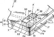
Figure 13 is a perspective illustration, and what show tray salver shown in Figure 9 forbids error logging mechanism.
Figure 14 is the skeleton view that shows CD and third embodiment of the invention tray salver.
Figure 15 is a sectional view, shows that CD has been contained in the state in the third embodiment of the invention tray salver.
Figure 16 is the skeleton view that shows CD and fourth embodiment of the invention tray salver.
Figure 17 is a sectional view, shows that CD has been contained in the state in the fourth embodiment of the invention tray salver.
Figure 18 is the skeleton view that shows the fifth embodiment of the invention tray salver.
Figure 19 is a sectional view, shows that CD correctly is contained in the state in the fifth embodiment of the invention tray salver.
Figure 20 is a sectional view, shows that CD is contained in state in the fifth embodiment of the invention tray salver with incorrect state.
Figure 21 is a perspective illustration, and what show that sixth embodiment of the invention is used for tray salver forbids error logging mechanism.
Figure 22 is a perspective illustration, and what show that seventh embodiment of the invention is used for tray salver forbids error logging mechanism.
Figure 23 is a perspective illustration, and what show that eighth embodiment of the invention is used for tray salver forbids error logging mechanism.
With reference to accompanying drawing, describe CD of the present invention and tray salver in detail.
At first, CD of the present invention is described.
The CD 1 of first embodiment of the invention constitutes by the first dish substrate 1A with the bonding second dish substrate 1B of the first dish substrate 1A, shown in Figure 4 and 5.
The first dish substrate 1A is made of printing opacity synthetic resin or similar material, becomes the dish that middle pit of the stomach 1D is arranged.The first dish substrate 1A has the annular signal recording area S that the layer that is reflected covers, as by the recording layer that constitutes as aluminium; And the protective seam of synthetic resin, as UV solidifiable resin.Form protective layer used in the upper surface that covers the reflection horizon, so that entirely cover a first type surface.If CD 1 is a read-only optical disc, the reflection horizon is by forming as aluminium.But,, then form by optical recording material if CD is a recordable disc.
The second dish substrate 1B is made of as polycarbonate resin synthetic resin, becomes the dish that middle pit of the stomach 1E is arranged.The bonding first dish substrate 1A, the second dish substrate 1B keeps the physical strength of the first dish substrate 1A as step disk.Be similar to the first dish substrate 1A, the second dish substrate 1B can establish reflection horizon and protective seam.In this case, the bonding second dish substrate 1B and the first dish substrate 1A face one another each reflection horizon or protective seam.
Form the second dish substrate 1B, make pit of the stomach inside dimension D3 wherein greater than the inside dimension D1 of pit of the stomach 1D among the dish substrate 1A and outside dimension D4 outside dimension D2 less than dish substrate 1A.Form the CD 1 that the neighboring has step 1C, as shown in Figure 4.
The design second dish substrate, the offset that makes pit of the stomach 1E inside dimension wherein be equal to or greater than bonding generation less than the value of the first CD 1A greater than the value or the second CD outside dimension of the first dish substrate 1A.
In above-mentioned CD 1, the state that the first dish substrate 1A and the second dish substrate 1B bond together is described.At first, the reference axis of centre clamp passes the middle pit of the stomach 1D of the first dish substrate 1A and the second dish substrate 1B respectively, and 1E is so that the location.Behind the location, the first dish substrate 1A and the second dish substrate 1B are bonded together mutually with UV solidifiable bonding agent.On at least one first type surface of the first or second dish substrate, apply UV solidifiable resin in advance.Behind above-mentioned relevant location, the UV ray is from the second dish substrate face irradiation, UV curing solidifiable bonding agent.
Utilize the above-mentioned CD 1 of first embodiment, because the inside dimension D1 at the pit of the stomach is less than the inside dimension at the pit of the stomach among the second dish substrate 1B among the first dish substrate 1A, simultaneously the outside dimension D2 of the first dish substrate 1A is greater than the outside dimension of the second dish substrate 1B, thereby can prevent to produce offset during bonding.So pit of the stomach 1F becomes the middle pit of the stomach 1D that coils substrate 1A in the CD 1 that forms.
Utilize this CD 1, the inside dimension D1 of pit of the stomach 1D is less than the inside dimension D3 of pit of the stomach 1E among the inside dimension D1 or the second dish substrate 1B in must preventing, the outside dimension D2 of pit of the stomach 1D is greater than outside dimension D2 in must preventing simultaneously, and second coils the outside dimension D4 of substrate 1B.
Utilize this CD 1, required gap between dish outer rim and the sabot of the aftermentioned tray salver inner wall part partly can be provided.
The CD 2 of second embodiment of the invention constitutes by the first dish substrate 2A with the bonding second dish substrate 2B of the first dish substrate 2A, shown in Fig. 6 and 7.
The first dish substrate 2A is made of the printing opacity synthetic resin as polycarbonate resin, becomes the dish that middle pit of the stomach 2D is arranged.The first dish substrate 2A has the annular signal recording area S that the layer that is reflected covers, as by the recording layer that constitutes as aluminium; And the protective seam of synthetic resin, as UV solidifiable resin.Form protective layer used upper surface, so that entirely cover the first type surface of the first dish substrate 2A in the covering reflection horizon.If CD 2 is CD-R, the recording layer that provides optical recording material to form replaces the A1 reflection horizon.
The second dish substrate 2B is made of as polycarbonate resin synthetic resin, becomes the dish that the middle pit of the stomach is arranged.The bonding first dish substrate 2A, the second dish substrate 2B keeps the physical strength of the first dish substrate 1A as step disk.Be similar to above-mentioned first embodiment, the second dish substrate 2B can establish reflection horizon and protective seam.In this case, the bonding second dish substrate 2B and the first dish substrate 2A face one another each reflection horizon or protective seam.
Form the second dish substrate 2B, make pit of the stomach inside dimension D7 wherein greater than the inside dimension D5 of pit of the stomach 2D among the dish substrate 2A and outside dimension D8 outside dimension D6 less than dish substrate 2A.Form the CD 2 that the neighboring has step 2C, as shown in Figure 7.
In above-mentioned CD 2, the state that the first dish substrate 2A and the second dish substrate 2B bond together is described.At first, the reference axis of unshowned centre clamp passes the middle pit of the stomach 2D of the first dish substrate 2A so that with the outside dimension as the pit of the stomach 2D location second dish substrate 2B among the first dish substrate 2A of benchmark.Behind the relative positioning, the first dish substrate 2A and the second dish substrate 2B are bonded together with UV solidifiable bonding agent.
Utilize the above-mentioned CD 2 of second embodiment, because the inside dimension D7 of pit of the stomach 2E is greater than the inside dimension D5 of pit of the stomach 2D among the first dish substrate 2A among the second dish substrate 2B, the outside dimension D8 of the first dish substrate 2A coils the outside dimension D6 of substrate 2A greater than first simultaneously, thereby can keep the skew of the relative second dish substrate 2B inside dimension of outside dimension to make it to be equivalent to or to be better than the skew that outside dimension relative first coils pit of the stomach 2F inside dimension among the substrate 2A.The middle pit of the stomach 2F of CD 2 becomes the middle pit of the stomach 2D of the first dish substrate 2A as a result.
Like this, to the first dish substrate 2A, pit of the stomach inside dimension simultaneously, is coiled substrate 2B, the skew that needn't keep outside dimension centering pit of the stomach inside dimension to second to the skew of outside dimension in needn't highly precisely keeping.As a result, to CD 2, relatively easily make the first dish substrate 2A and the second dish substrate 2B, thereby reduce production costs.
This CD 2 can provide required gap between dish outer rim and the sabot of the aftermentioned tray salver inner wall part partly, thereby can the low-cost production tray salver.
In addition, this CD 2 can highly precisely keep having the skew between the pit of the stomach 2D and CD 2 outer rims among the first dish substrate 2A of signal recording area S, thereby can make aftermentioned tray salver sabot part inner wall part and the required gap of coiling between 2 outer rims reaches minimum value.So will highly precisely not remain on the record/playback apparatus face by CD 2, so that reduce the production cost of record and replay device.
The following describes the tray salver of the present invention that the above-mentioned first embodiment CD is housed.
With reference to Fig. 9 and 10, tray salver 10 has the main cartridge part 14 that is made of first box 12 and second box 13, and each half box is the dish of the shallow degree of depth.CD 1 rotatably is contained in the main cartridge part 14.Valve 16 is contained in the front side of main cartridge part 14 slidably.At the reverse side formation dish insertion/conveying end 17 of main cartridge part 14, coiling 1 thus can insert or take out.But CD 1 herein is the CD of recording information signal.
On each opposite inner face of upper and lower half box 12,13, on same circumference, form the arcwall spare of a plurality of interruptions, in case interior edge fit wall spare 21a, 21b.These arcwall spares constitute sabot wall spare 19 together.The sabot wall spare 19 of first box 12 is slightly larger than the overall diameter of dish substrate 1B and the height thickness greater than dish substrate 1B.The sabot wall spare 19 of second box 13 is slightly larger than the overall diameter of dish substrate 1A and the height thickness greater than dish substrate 1A.On, when second box 12,13 lumped together, the inside surface of sabot wall spare 19 and half box 12,13 constituted sabot part 20 together.It is convex substantially that this sabot part 20 limits a space and a cross section that is slightly larger than CD 1 profile.Sabot part 20 restriction is contained in moving of CD 1 in the box main body part 14.
In half box 12,13, form mouth 22,23 respectively, divide from central division to a plane of half box 12,13 and extend.When tray salver 10 was loaded on record and the replay device, the Pan Tai of this device charged into the middle part 22a of mouth 22,23,23a.Constitute Pan Tai so that rotation drives the CD 1 that is contained in the sabot part 20.
The middle part 22a of continuity mouth 22,23,23a, part 22b, 23b extends to a plane of half box 12,13.The interior outer rim that these parts 22b, 23b allow the partial record district 14 of CD 1 to cross dish is at least revealed the outside.These parts 22b, 23b is with noting down and reset mouth 23.That is, when CD 1 was contained on record and the replay device, as these parts 22b of the record/playback unit through port 22,23 of optical take-up apparatus, 23b faced CD 1.
At the outside surface of main cartridge part 14, form recessed 26.When tray salver 10 was loaded on record and the replay device, by being located at the valve open/close mechanism on this device, valve 16 was remained silent mobile between 22,23 position and the position of opening mouth 22,23 in the pass, and the moving range of corresponding valve 16 forms recessed 26.
When tray salver 10 did not use, when promptly tray salver 10 was not loaded on record and the replay device, valve 16 prevented that dust and dirt through port 22,23 from entering sabot unit 20 and being deposited on the CD 1 that is contained in the sabot unit 20.Under remained silent 22,23 state in the pass, valve 16 prevented the recording areas S of hand or finger contact disc 1.Valve 16 is made by the pressed metal thin plate, and by a pair of first type surface part 28a, 28b and interconnected these first type surface parts 28a, the web member 29 of 28b constitutes, and this is to first type surface 28a, and the size of 28b is decided to be the mouth 22,23 of closing upper and lower half box 12,13.Form valve 16 and make it to have the U-shaped cross section.
Above-mentioned valve 16 be installed in main cartridge part 14 recessed 26 in, set main cartridge part 14.The end of first type surface part 28 is compressed by valve keeper 34, and unshowned valve guide member is installed in the supporting guide channel that forms in the main cartridge part 4 simultaneously.Tray salver 10 is kept by an end of unshowned spring, and its other end is kept by main cartridge part 4.Valve 16 spring thus constantly is offset with the direction shown in the arrow A among Fig. 9.When valve 16 was loaded on record and the replay device, the valve of valve opening mechanism one of was opened among pins engages otch 31a or the 31b.This makes valve slide into and open mouthfuls 22,23 position with remain silent from the pass 22,23 position of direction shown in the arrow B among Fig. 9.
Though above-mentioned valve 16 is to move in a direction,, valve also can be configured to move with right on a left side.At this moment, need on the front side of each first box 12 and second box 13, form recessed 16 in the main cartridge part 14 in the whole zone.
On two horizontal sides of main cartridge part 14, form the recessed 36a of insertion control, 36b to the front side.When tray salver 10 was loaded on record and the replay device by automatic loading device, these inserted the recessed 36a of control, the insertion control pin on the 36b engagement automatic loading device.When being moved by automatic loading device, inserts tray salver 10 the recessed 36a of control, the insertion control pin on the 36b engagement automatic loading device, the precalculated position in moving to record and replay device.
Form and insert the recessed 36a of control, 36b extends to second box 13 from first box 12.Because insert the recessed 36a of control, 36b passes the whole thickness of tray salver and forms, when a plurality of tray salvers 10 were contained in the sabot cartridge device with stacked state, whether rule was located can to identify tray salver 10.If the tray salver of packing into 10 is the rule location not, insert the recessed 36a of control, 36b is alignment mutually not, thus it is incorrect to discern which tray salver location.
On two horizontal sides of main cartridge part 14, form taking-up control otch 37a, 37b to rear side.When tray salver 10 from record and replay device when taking out automatically, these take out control otch 37a, 37b meshes unshowned taking-up pin on the automatic loading device.When tray salver 10 is moved by the precalculated position of automatic loading device from record and replay device, take out control otch 37a, the 37b engagement is located at the taking-up pin on the automatic loading device.
Formed taking-up control otch 37a, 37b be not from first box 12 to second box 13, but intermediate altitude face from second box 13 to first box 12 upstanding edge wall spares 21.Like this, when tray salver 10 manually when dish record takes out with replay device, when promptly not using automatic loading device, these take out controls otch 37a, 37b is not blocked by the peripheral wall part of the tray salver insertion mouth of dish record and replay device, thereby can smooth insertion or taking-up.
In the main cartridge part 14, formation dish insertion/ejection door 17 on the offside that valve 16 sides are housed, as shown in figure 11.When tray salver did not use, when promptly the tray salver unloaded was on dish record and replay device, dish insertion/ejection door 17 was closed by the lid 40 that is installed on the main cartridge part 14 rear side hinges, and lid 40 is used for relative main cartridge part 14 ON/OFF.
On two horizontal sides of the dish insertion/ejection door 17 of first box 12, form rib shape keeper 41.By keeper 41 is set, form insertion/ejection door 17, make it the overall cross-sectional area of size, and open with the step-like rectangle of each upper edge greater than CD 1.Dish insertion/ejection door 17 is made of the first opening 17a and the second opening 17b, the first opening 17a is limited by the keeper 41 of step 1C of alignment CD 1 and the size of its long side is slightly larger than the diameter of the less dish substrate 1B of diameter and the size of short side is slightly larger than the thickness of dish substrate 1B, and the size of the long side of the second opening 17b is slightly larger than the diameter of the bigger dish substrate 1A of diameter and the size of its short side is slightly larger than the thickness that coils substrate 1A.
Dish insertion/the ejection door 17 of said structure is inside and outside with main cartridge part 14, and the sabot part 20 in the main cartridge part 14 communicates.Prevent that like this CD 1 from having passed through to coil insertion/bullet mouthful 17 insertion sabot parts 20 with wrong way.When CD 1 is inserted sabot part 20, have only first mouthful of 17a of substrate 1B alignment of CD 1 and second mouthful of 17b of substrate 1A alignment of CD 1, could so insert CD 1 when inserting CD by dish insertion/ejection door 17.On the contrary, if second mouthful of 17b of substrate 1B alignment of first mouthful of 17a of the substrate 1A of CD 1 alignment and CD 1, during with CD 1 insertion dish insertion/ejection door 17, the step 1C of CD 1 props up keeper 41, thereby stops CD 1 to insert sabot part 20 inside.
Be used to close the lid 40 that coils insertion/ejection door 17 and have the principal part 45 that is used to close dish insertion/ejection door 17, be located at the hinge portion 46 of principal part 45 ends, and be located at principal part 45 another terminal block pieces 47.
By being contained in the not shown mounting portion on the principal part 45 on the unshowned fulcrum post, hinge portion 46 supporting principal parts 45 are so that main cartridge part 14 and ON/OFF relatively, and fulcrum post is located on the end of main cartridge part 14 dish insertion/ejection doors 17.Be provided with block piece 47 on another opposite end of principal part 45, it and principal part 45 are in aggregates.The far-end of block piece 47 is made as keeper 49.
Under the state of closing dish insertion/ejection door 17, the unshowned projection of lid 40 engagements, this projection is located at another opposite end of the dish insertion/ejection door 17 of main cartridge part 14, so even vibrated during tray salver 10 transmits, it is not opened yet.When opening dish insertion/ejection door 17, lid 40 breaks away from block piece 47 unshowned projectioies, so that open with direction shown in the arrow C among Figure 11.
When anti-error recording mechanism 50 is in primary importance, the i.e. position shown in the X in Figure 13, the horizontal edge of stop portions 54 holding trays 1 of anti-error record spare 51, be convenient to simultaneously to write down and replay device on the test section of misdescription record pick-up unit enter, prevent to write the fresh information signal like this.When primary importance, i.e. the X of position shown in Figure 13, anti-error record spare 51 forbid coiling 1 and take out from dish insertions/conveying end 17, forbid simultaneously writing new information signal coiling on 1.
When anti-error record spare 51 slides to the second place, i.e. position shown in the Y among Figure 13, anti-error recording mechanism 50 discharges from the state of stop portions 54 holding trays 1 horizontal edge.This can take out CD 1 from dish insertion/conveying end 17, and the misdescription record pick-up unit of forbidding simultaneously being located on record and the replay device enters, thereby allows the new information signal of record.When the second place, i.e. position shown in the Y among Figure 13, anti-error record spare 51 can take out CD 1 from dish insertions/conveying end 17, allows to write down new information signal simultaneously.
Be loaded on record and the replay device if the above-mentioned tray salver 10 of above-mentioned CD 1 is housed, tray salver 10 is located by unshowned detent mechanism, and valve 16 slides with direction shown in the arrow B among Fig. 9 and makes mouth 22,23 expose the outside simultaneously.The CD 1 that is contained in the tray salver 10 also can be rotated thus by Pan Tai on record and the replay device and anchor clamps spare chucking.
Utilize above-mentioned tray salver 10, when dish 1 took out from optical disk cartridge 10, the anti-error record spare 51 of anti-error recording mechanism 50 entered the second place simultaneously, i.e. position Y shown in Figure 13.Can inform that like this user can write on the CD 1 that exposes.If CD 1 can write new information signal being loaded under the state of tray salver 10 of not packing on record and the replay device on CD 1.
And, utilize tray salver 10, if CD 1 is contained in the tray salver 10, and the anti-error record spare 51 of anti-error recording mechanism 50 is in primary importance, promptly the position X shown in Figure 13 can inform that then the user can not write on CD 1.
If under CD 1 is contained in state in the above-mentioned tray salver 10, tray salver 10 is loaded on record and the replay device, location tray salver 10, simultaneously along with valve 16 moves with the direction shown in the arrow B among Fig. 9, make mouthfuls 22,23 expose outside.
The middle part 22a of through port 22,23, one of 23a, the Pan Tai on record and the replay device charges into the inside of record and replay device.The CD 1 that is contained in the tray salver 10 is arranged on the anchor clamps spare on record and the replay device and coils the platform clamping, thereby rotatable.
When tray salver did not use, the CD that is contained in the tray salver 10 can exchange with a new CD.At this moment, open and coil insertion/conveying end 17 towards the outside by the lid 40 of tray salver 10, the tray salver upset, mouth 17 is downward.CD 1 slidably and outwards takes out.In main cartridge part 14 that CD 1 is packed into, being made as towards first mouthful of 17a of CD 1 towards dish substrate 1B side, and coil 1 be made as towards second mouthful of 17b towards dish substrate 1A side, lid 40 is in closed condition.CD 1 inserts by dish insertion/conveying end 17 under this state.Because formed dish insertion/ejection door 17 sizes are greater than the cross section of whole CD 1, and opening one-tenth is at the step-like rectangle of each upper edge of registration CD 1 step 1C, so CD 1 is not put upside down the danger of insertion.
Therefore, utilize this tray salver 10, the record and the playback side plug that will write down or reset be located at record and replay position, and the danger that is recorded in the information signal of wanting on the CD is not wiped in the danger that does not just have the user because of carelessness CD 1 to be inserted main cartridge part 14 simultaneously because of carelessness yet.
In above-mentioned tray salver 10, the sabot part of supposing to form in the main cartridge part 14 20 is similar to the shape of dish insertion/conveying end 17 at the step-like rectangle of each upper edge.But, it should be noted that the sabot wall spare of second box 12,13 is slightly larger than the overall diameter of dish substrate 1A, so that determine to have the sabot part of square-section.
CD and the tray salver of the 3rd embodiment are described now.Referring to Figure 14 and 15, tray salver 60 is described at first.Tray salver 60 has a circumferential rib 61a on the CD 61 inside circumferences part that does not have recording information signal.Main cartridge part 63 have one with the essentially identical dish insertion/conveying end 83 of CD 61 cross sectional shapes.Represent no longer to describe with identical mark with part or parts that tray salver shown in Fig. 9 to 11 10 is shared.
Be similar to the tray salver 10 shown in Fig. 9 to 11, tray salver 60 has by first box 62 and second box 63 unites the main cartridge part 64 that forms, and each first box 62 and second box 63 are the dish type of the shallow degree of depth of cardinal principle.CD 61 as CD-WORM or magneto-optic disk, rotatably is contained in the main cartridge part 64.Valve 16 is slidably mounted on the front side of main cartridge part 64.The rear side of main cartridge part 64 is provided with dish insertion/conveying end 83, inserts or take out CD 61 by it.On, the similar of second box 62,63 is in half box 12,13 of the tray salver shown in Fig. 9 to 11 10.
The CD 61 that is contained in the tray salver 60 is made of a dish substrate 61b, forms the information signal recording district on an one first type surface.This dish substrate 61b has wherein the not inner edge retaining part 61c of the center arrangement of recording information signal, wherein recording information signal from the radially outer recording areas 61d of inner edge retaining part 61c, and the non-recording areas 61e of avris outside recording areas 61d is radially outer of recording information signal not wherein.CD 61 is provided with upright circumferential rib 61a, and it extends along the outward flange of the inner edge retaining part 61c on the signal record first type surface, and the signal record first type surface promptly writes down and resets surperficial.So dish becomes the square-section with outstanding quadrilateral core.
The inside surface of main cartridge part 64 is provided with outer avris sabot wall spare 78 and interior avris sabot wall spare 79.Outer avris sabot wall spare 78 is made of a plurality of arcwall spares on the same circumference.On the other hand, interior avris sabot wall spare 79 is formed on the inside surface of first box 62, its align when CD 61 is contained in the main cartridge part 64 outward flange of upright circumferential rib 61a.Outer avris sabot wall spare 78 is slightly larger than the overall diameter of CD 61 and is slightly thicker than the thickness of CD 61.Interior avris sabot wall spare 79 highly is slightly larger than the height of rib 61a.On, when second box 62,63 lumped together, sabot wall spare 78,79 was close to mutually, determined a sabot part 80, and it has the square-section of outstanding quadrilateral core.The amount of movement of CD 61 in main cartridge part 64 that 80 restrictions of sabot part are mounted in it.
The opposite side that main cartridge part 64 front sides of valve 16 are housed is provided with dish insertion/conveying end 83.Tray salver 60 is the time spent not, and when promptly tray salver 60 was not loaded on record and the replay device, dish insertion/conveying end 83 was closed by the lid of installing 40, and lid 40 is used for ON/OFF on main cartridge part 64 dorsal parts.
On the part of first box 62, alignment inner edge retaining part 61c and recording areas 61d, form stop portions 41 at dish insertion/ejection door 83.Divide 41 by the handicapping stopper, formation dish insertion/ejection door 83 makes it size greater than the cross section of whole CD 1 and be shaped as the rectangle of projection at core.Dish insertion/ejection door 183 is made of the first opening 83a and the second opening 83b, the first opening 83a is limited by the stop portions 41 of alignment CD 1 inner edge retaining part 61C and the size of its long side is slightly larger than the diameter of inner edge retaining part 61C and the size of short side is slightly larger than the height of rib 61a, and the size of the long side of the second opening 83b is slightly larger than the diameter of dish substrate 61b and the size of short side is slightly larger than the thickness that coils substrate 61b.
Dish insertion/ejection door 83 maintenances of above-mentioned structure communicate with the inboard of the sabot part 80 of main cartridge part 64.Prevent that like this CD 61 from inserting sabot part 80 with wrong way by dish insertion/ejection door 83.When CD 61 is inserted the sabot part 80 of tray salver 60, have only first mouthful of 83a of inner edge retaining part 61C alignment and second mouthful of 83b of substrate 61B alignment of CD 61, could insert CD 61 when inserting CD by dish insertion/ejection door 83.On the contrary, if before opposite, turn over side position with normal insertion position, i.e. first mouthful of 83a of substrate 61b alignment and second mouthful of 83b of inner edge retaining part 61c alignment, during with CD 61 insertion dish insertion/ejection doors, CD 61 can't insert.
When tray salver did not use, the CD that is contained in the tray salver 60 can exchange with a new CD, and the situation of tray salver 60 just shown in Figs. 9 to 11 is the same.At this moment, open and coil insertion/conveying end 83 towards the outside by the lid 40 of tray salver 60, the tray salver upset, mouth 83 is downward.CD 61 slidably and outwards takes out then.In main cartridge part 64 that CD 61 is packed into, the inner edge retaining part 61C of CD 61 is made as towards first mouthful of 83a, and dish substrate 61b is made as towards second mouthful of 83b, and lid 40 is in closed condition.CD 1 inserts main cartridge part 64 by dish insertion/conveying end 83 under this state.Because formed dish insertion/ejection door 83 sizes are greater than the cross section of whole CD 1, and opening one-tenth is at the step-like rectangle of each upper edge of registration CD 1 inner edge retaining part 61C, so CD 1 is not put upside down the danger of insertion.
Therefore, utilize this tray salver 60, record that writes down not wanting or reset and playback side are located at record and replay position, the danger that does not just have the user because of carelessness CD 61 to be inserted main cartridge parts 64, and the while is not wiped the danger that is recorded in the information signal of wanting on the CD 1 because of carelessness yet.
In above-mentioned tray salver 60, the sabot part of supposing to form in the main cartridge part 64 80 is similar to the shape of dish insertion/conveying end 83 at the step-like rectangle of each upper edge.But, it should be noted that the sabot wall spare 78,79 of second box 62,63 also can be slightly larger than the overall diameter of dish substrate 61b, the height of sabot wall spare 78,79 has the sabot part of square-section for the thickness of dish substrate 61b and the height sum of rib 61b so that constitute.
The CD and the tray salver of fourth embodiment of the invention are described now.The tray salver 90 of the 4th embodiment at first, is described with reference to Figure 16 and 17.In order to insert or take out the CD 91 with oblique outside, this tray salver 90 has main cartridge part 92, and main cartridge part 92 is provided with the dish insertion/conveying end 93 identical with CD 91 cross sectional shapes.Represent with identical mark with shared part of tray salver shown in Fig. 9 and 10 10 and parts and omit corresponding description, so that simplify.
Tray salver 90 has the main cartridge part 94 that is made of first box 92 and second box 93, first box 92 and second box 93 be similar to tray salver shown in Fig. 9 to 11 10 on, second box 12,13, general shape is the dish of the shallow degree of depth.CD 91 as CD-WORM or magneto-optic disk, rotatably is contained in the main cartridge part 94.Valve 16 is slidably mounted on the main cartridge part 94.The rear side of main cartridge part 94 is provided with dish insertion/conveying end 95, inserts or take out CD 91 by it.
The CD 91 that is contained in the tray salver 90 is made of a dish substrate 101, forms interblock on an one first type surface.This dish substrate 101 has wherein the not inner edge retaining part 102 of the center arrangement of recording information signal, wherein recording information signal from inner edge retaining part 102 radially outer recording areas 103, and the non-recording areas 104 of avris outside recording areas 103 is radially outer of recording information signal not wherein.The CD 91 of said structure has its information signal recording first type surface, promptly record with reset surperficially, its overall diameter is less than the opposite side first type surface of recording information signal not, so the outward flange of CD 91 is the inclined-plane, CD 91 cross sections are roughly frustoconical.
Be provided with sabot wall spare 110 on first box 92 or second box 93, it is made of a plurality of arcwall spares on the same circumference.Sabot wall spare 110 forms inclined wall spare, and it adapts to the profile of CD 91 and is slightly larger than the overall diameter of CD 91.On, when second box 92,93 lumps together, the sabot part 111 that sabot wall spare 110 is determined therein.Therefore 111 restrictions of sabot part are contained in the amount of movement of the CD 91 in the main cartridge part 94.
The opposite side that main cartridge part 94 front sides of valve 16 are housed is provided with dish insertion/conveying end 95.Tray salver 90 is the time spent not, and when promptly tray salver 90 was not loaded on record and the replay device, dish insertion/conveying end 95 was closed by the lid of installing 40, and lid 40 is used for ON/OFF on main cartridge part 94 dorsal parts.
Dish insertion/ejection door 95 has stop portions 113 on two horizontal sides of first box 92, make it be roughly the frustoconical of corresponding CD 91 cross sectional shapes.These stop portions 113 are formed on the rib on the two horizontal sides of first box 92.The long side that dish insertion/ejection door 95 is of a size of on first box 92 sides is slightly larger than the respective disc record and the dish 91 first type surface diameters on surface of resetting, and the long side on second box 93 sides is slightly larger than the offside first type surface of CD 91, and the size of bead height is slightly larger than the thickness of CD 91.
Dish insertion/the ejection door 95 of above-mentioned structure communicates with sabot part 80 inboards of main cartridge part 111.Prevent that like this CD 91 from inserting sabot part 111 with wrong way by dish insertion/ejection door 95.When CD 91 is inserted sabot part 111, have only the record of CD 91 and playback main surface side to be made as and the first type surface offside of CD 91 is made as towards second box 93, could insert CD 91 when coiling insertion/ejection door 95 insertion CDs towards the last box 92 of dish insertions/ejection door 95.On the contrary, if turn over side position before oppositely with opposite with normal insertion position, be that the record of CD 91 and playback main surface side are made as towards the following box 92 of dish insertion/ejection door 95 and the first type surface offside of CD 91 is made as towards first box 93, during with CD 91 insertion dish insertion/ejection doors, CD 91 can't insert sabot part 111.
When tray salver did not use, when promptly tray salver was not loaded on record and the replay device, the CD that is contained in the tray salver 90 can exchange with a new CD.At this moment, open and coil insertion/conveying end 95 towards the outside by covering 40, the tray salver upset, mouth 95 is downward.CD 61 slidably and outwards takes out then.In main cartridge part 94 that CD 91 is packed into, the record of CD 61 and playback first type surface are made as towards first box side of dish insertion/conveying end 95 and the first type surface offside that coils is made as second box side towards second mouthful of 83b, closing cap 40.CD 1 inserts in the main cartridge part 94 by dish insertion/conveying end 95 under this state.Because formed dish insertion/ejection door 95 sizes are greater than the cross section of whole CD 91, and opening becomes frustoconical, so CD 1 is not put upside down the danger of insertion.Therefore, utilize this tray salver 90, the record and the playback side of not record or playback are located at record and replay position, and the danger that is recorded in the information signal of wanting on the CD 1 is not wiped in the danger that does not just have the user because of carelessness CD 91 to be inserted main cartridge parts 94 simultaneously because of carelessness yet.
In above-mentioned tray salver 90, the sabot part of supposing to form in the main cartridge part 94 111 is for being similar to the frustoconical of dish insertion/conveying end 83.But it should be noted that sabot part 111 also can be the square-section, the height that sabot wall spare 110 sizes of first box 92 and second box 93 are slightly larger than the overall diameter of CD 91 and sabot wall spare 110 is slightly larger than the thickness of CD 91.
The CD and the tray salver of fifth embodiment of the invention are described now.The tray salver 120 of the 5th embodiment at first, is described with reference to Figure 17 to 20.Below, suppose that the CD 2 of second embodiment is contained in the tray salver 120.
This tray salver 120 is made of the box-like main cartridge part 121 of whole minimal thickness and has a first type surface of opening, but and the lid 122 of switch main cartridge part 121 first type surfaces of opening.By ON/OFF lid 122 can insert CD 2 and from tray salver 120 with its taking-up.The CD 2 of this moment is CD-R of energy recording information signal.
The bottom surface 143 of sabot part 141 is provided with window 148, and window 148 extends from the middle part to the outside of covering 122 main cartridge part 121 is housed.This window 148 is charged into mouthful 148a and rectangle record and mouthful 148b that resets by Pan Tai and is constituted, Pan Tai charges into the dish platform shape that is located at when mouthful 148a is loaded on record and the replay device corresponding to tray salver 120 in record and the replay device, and rectangle record and mouthful 148b that resets are used for outside the S of recording areas at least with CD 2 partly exposes, and it is charged into mouthful 148a from Pan Tai and covers 122 main cartridge part 121 outsides and cross its outer edge to being equipped with.
Charge into the rib that forms on the limit of mouthful 148a as setting face 151 at Pan Tai, tray salver 120 without the time CD 2 put thereon.That is, tray salver 120 is the time spent not, and the inner edge retaining part of dish substrate 2A is near setting face 151.
These window 148 installation valve align, it is opened when tray salver 120 is loaded on record and the replay device, do not enter sabot part 141 with dust protection and dirt and be deposited on the CD 2 of packing into wherein and do not close between the operating period, and prevent that hand or finger from touching the recording areas S of CD 2 at tray salver 120.
On the inside surface of lid 122, form the rib 160 of the non-recording areas in alignment CD 2 neighborings highlightedly.The vertical vibration that CD 2 under 122 closed conditions is covered in rib 160 restrictions.
When the above-mentioned tray salver 120 that CD 2 is housed was loaded on record and the replay device, record was charged into Pan Tai with Pan Tai on the replay device side and is charged into a mouthful 148a, and dish folder 156 chucking optical disks 2 on lid 122 are so that rotate driving CD 2.
When tray salver did not use, when promptly tray salver was not loaded on record and the replay device, the CD that is contained in the tray salver 120 can exchange with a new CD.At this moment, utilize and to cover 122 and be in open mode, commutative CD 2.
In main cartridge part 121 that CD 2 is packed into, the dish substrate 2A of CD 2 is faced down, promptly to the bottom surface 143 of box main body part 121 sabot parts 141, with the CD sabot part 141 of packing into, lid 122 keeps closing, as shown in figure 19.At this moment, the stop portions 142 of sabot part 141 engagement alignment CDs 2 step 2C.In this case, lid 122 is closed by cooperating recesses 155 definitely.
On the contrary, if the dish substrate 2B of CD 2 is directly downward,, CD 2 is packed in the sabot part 141 promptly to the bottom surface 143 of main cartridge part 121 sabot parts 141, as shown in figure 20, dish substrate 2B is located on the setting face 145 and the step 2C of CD 2 does not mesh stop portions 142.So dish substrate 2A is outstanding by the recess 155 of main cartridge part 121, lid 122 is not closed.
Utilize above-mentioned cooperation 120, the danger that CD 2 does not have the reversed position mistake to insert.Therefore, utilize this tray salver 120, record that writes down not wanting or reset and playback side are located at record and replay position, the danger that does not just have the user because of carelessness CD 120 to be inserted main cartridge parts 121, and the while is not wiped the danger that is recorded in the information signal of wanting on the CD 2 because of carelessness yet.
The 6th embodiment of tray salver is described now.The tray salver 260 of the 6th embodiment comprises the anti-error recording mechanism 263 that is installed on the lid 262 of closing dish insertion/conveying end 261.Represent not do corresponding description to simplify with part or parts that tray salver 10 is shared with identical mark.
Referring to Figure 21, the horizontal side in the behind of main cartridge part 14 has dish insertion/conveying end 261, inserts the CD 1 that illustrates with reference to Figure 4 and 5 by it.Dish insertion/conveying end 261 has the first notch portion 261a, the second notch portion 261b and the 3rd notch portion 261c, the size of the long side of the first notch portion 261a is slightly larger than the thickness that the size of lacking side than the diameter of minor diameter dish substrate 1B is slightly larger than dish substrate 1B, the size of the long side of the second notch portion 261b is slightly larger than the diameter of major diameter dish substrate 1A and the size of short side is slightly larger than the thickness of dish substrate 1A, and the similar of the 3rd notch portion 261c is in the first notch portion 261a.CD 1 with square-section of outstanding quadrilateral core can directly make progress dish substrate 1B or coil substrate 1A and directly upwards pack into by dish insertion/conveying end 261.
The lid 262 of closing dish insertion/conveying end 261 has the principal part 275 of closing dish insertion/conveying end 261, is formed on the hinge and the block piece 276 that is formed on principal part 275 another opposite ends of principal part 275 1 ends.
Principal part 275 has a closed 277 on its side in the face of dish insertion/conveying end 261.Closed 277 is formed on the same curved surfaces with the horizontal side of CD 1.When lid 262 had been closed dish insertion/conveying end 261, lid was determined sabot part 20 together with the inside surface of half box 12,13.Anti-error recording mechanism 263 is installed on the first type surface 278 of principal part 275.When lid 262 had been closed dish insertion/conveying end 261, principal part 275 flushed with the horizontal side of first type surface and main cartridge part 14.On the opposite end of principal part 275, block piece 276 and principal part 275 whole formation.Block piece 279 is formed on the far-end of block piece 276.
When closing dish insertion/conveying end 261, above-mentioned lid 262 engagements are located at the not shown projection of dish insertion/conveying end 261 opposite ends of main cartridge part 14, can not open because of the vibration accident that is produced between tray salver 260 transmission periods thereby cover 262.When lid 262 was opened dish insertion/conveying end 261, block piece 276 moved the projection that breaks away from main cartridge part 14 owing to opening.
Anti-error recording mechanism 263 is by being installed in the anti-error record spare 281 that covers on 262, and the control opening 283 that forms in opening 282 and first box 12 constitutes, and opening 282 is located at and cover in 262 the first type surface 278, so that outside anti-error record spare 281 exposes.
Anti-error record spare 281 has drive part 284 and the stop portions 285 that is located on drive part 284 both sides.Stop portions 285 has the otch 286 that extends to drive part 284 on the thickness direction of bonding pad.
Opening 282 and control opening 283 are made as the elongated open of extending along main cartridge part 14 horizontal sides, formation dish insertion/conveying end 261 in the main cartridge part 14.These openings 282,283 allow the drive part 284 of anti-error record spare 281 to reveal to the outside, allow anti-error record spare 281 to slide therein simultaneously.
Utilize above-mentioned anti-error recording mechanism 263, close dish insertion/conveying end 261 as operculum 262, drive part 284 exposes by control opening 1283.So lid 262 is by stoping anti-error record spare 281 lockings that drive on the opening direction.When tray salver 260 was loaded on record and the replay device, anti-error record spare 281 stoped the test section of the misdescription record pick-up unit that is located on record and the replay device to enter, thereby prevents to write on CD 1 new information signal.
Drive on opening direction as operculum 262, the stop portions 285 of at first anti-error record spare 281 is removed.Because stop portions 285 is provided with the drive part 284 by otch 286, can easily it be removed by push drive part 284 open from above.Because stop portions 285 removes from opening 282,283, thereby anti-error record spare 281 can discharge and covers 262, makes to cover 262 and can open.
Be loaded on record and the replay device if having the tray salver 260 of the anti-error record spare 281 of breaking-up, the test section that is located at the misdescription record pick-up unit on the device enters opening 282,283, allows to write on CD 1 new information signal.
Like this, if CD 1 so far takes out from tray salver 260 as yet, the user can recognize and not allow to write new information signal.If the user takes out CD 1 from tray salver 260, the user can recognize can not write new information signal.
The 7th embodiment of tray salver is described now.
In the tray salver 290 of the 7th embodiment, be suitable for closing the auxiliary member that anti-error recording mechanism 291 is installed on the lid 292 that coils insertion/conveying end 17, as shown in figure 22.These embodiment others are identical with the tray salver 10 shown in Fig. 9 to 11.
The lid 292 of closing dish insertion/conveying end 17 has the principal part 293 that is used to close dish insertion/conveying end 17, is located at the not shown hinge of principal part 293 1 ends, and the block piece 294 that is located at principal part 293 opposite ends.
In the face of principal part 293 sides of coiling insertion/conveying end 17 are provided with closed 295.Closed 295 has and the identical curved surfaces of CD 1 horizontal lateral edges.When lid 292 had been closed dish insertion/conveying end 17, lid formed part sabot part 20.Anti-error recording mechanism 291 is set on the first type surface 296 of principal part 293.When lid 292 had been closed dish insertion/conveying end 17, principal part 293 flushed with the horizontal side of first type surface and main cartridge part 14.Be located at the block piece 294 and principal part 293 whole formation of principal part 293 opposite ends, and have stop portions 297 at its far-end.
When above-mentioned lid 292 was closed dish insertion/conveying end 17, stop portions 297 engagements were located at the not shown projection of main cartridge part 14 dish insertion/conveying ends 17 opposite ends, even so that lid is not also opened between 290 delivery periods under the vibrative situation at tray salver.When dish insertion/conveying end 17 is opened, discharge block piece 294, cover 292 thereby can open.
Utilize above-mentioned anti-error recording mechanism 291, when closing dish insertion/conveying end 17 as operculum 292, anti-error record spare 301 exposes by unshowned opening in first box 12.So lid 292 is by 301 lockings of anti-error record spare, can not drive opening direction.Utilize anti-error record spare 301, the test section of the error logging pick-up unit of record and replay device can't enter when tray salver 290 is loaded on record and the replay device, thereby prevents from new information signal is write on the CD 1.
Drive and to cover 292 o'clock opening direction, the web member 303 of anti-error record spare 301 is at first removed.Web member 303 is destroyed by the anti-error record spare 301 that promotes from above.Because web member 303 destroys, anti-error record spare 301 is removed from opening 302.The result is covered 292 and is discharged, and can open thereby cover 292.
If having cut the tray salver 290 of anti-error record spare 301 is loaded on record and the replay device, the test section of the error logging pick-up unit of record and replay device can enter the not shown control opening in opening 302 and first box 12, so new information signal can write on the CD 1.So if CD 1 never takes out from tray salver 290, the user can recognize can not write new information signal.In case the user takes out CD 1 from tray salver 290, he or she can recognize can not write new information signal.
Above-mentioned lid 292 is provided with the auxiliary member 305 of anti-error record spare 301, and it is integral with the first type surface 296 of lid.In case anti-error record spare 301 is removed, this auxiliary member 305 is contained in the opening 302.Auxiliary member 305 constitutes by operating parts 306 with from the outstanding elastic component 307 of the horizontal edge of operating parts 306, and is connected to principal part 293 by web member 308.Auxiliary member 305 is identical with anti-error record spare 301 profiles.Elastic component 307 is outstanding so that size is slightly larger than opening 302 from the edge of anti-error record spare 301.
When being contained in the opening 302, auxiliary member 305 at first cuts from web member 308.At this moment, auxiliary member 305 is by making progress or descending warpage to cut.The auxiliary member 305 that so cuts is by being fixed by the elastic component 307 crooked openings 302 that push.Elastic component 307 sizes are slightly larger than opening 302, thereby by pushing away auxiliary member 305, elastic component 307 resilient movement are so that enter opening 302.Because elastic component 307 sizes are slightly larger than the peripheral wall of opening 302 and engagement opening 302, so tray salver does not exist elastic component 307 to shift out from opening 302 because of carelessness between 290 delivery periods danger.By using auxiliary member 305 in this way, can reuse tray salver 290.
The 8th embodiment of tray salver is described now.The tray salver 320 of the 8th embodiment is included near the anti-error recording mechanism 322 the dish insertion/conveying end 321 of main cartridge part 14, as shown in figure 23.Represent not remake corresponding explanation with same tag so that simplify with part or parts that tray salver 10 is shared.
CD 1 shown in the Figure 4 and 5 enters in the main cartridge part 14 dish insertion/conveying end 321 that horizontal side forms behind.Dish insertions/conveying end is rectangle and is of a size of that long side is slightly larger than than the diameter of major diameter dish substrate 1A and its short side is slightly larger than and coils substrate 1A and 1B thickness sum.The structure of dish insertions/conveying end 321 makes the CD 1 with the step-like square-section of widthwise edge can insert the sabot part, and no matter be dish substrate 1B upwards or dish substrate 1A makes progress.
Dish insertion/conveying end 321 is opened or closed by the lid 40 of tray salver shown in Fig. 9 to 11 1.
Control opening 327 forms arc, and the long side of arc is parallel to main cartridge part 14 horizontal sides extends, and dish insertion/conveying end 321 is located in the main cartridge part 14.Anti-error record spare 326 drives to rotate block piece 325 along control opening 327 with the direction shown in arrow C among Figure 23 and the D.
Above-mentioned anti-error recording mechanism 322 is in primary importance, shown in the V, represents the horizontal side of block piece 325 locking disks 1 among Figure 23, and 326 preventions of anti-error record spare write new information signal.Because anti-error record spare 326 slides, above-mentioned anti-error recording mechanism 322 is in the second place, and shown in the W, the state of block piece 325 locking disks 1 horizontal side is removed in expression among Figure 23, dish 1 can take out from dish insertion/conveying end 321, and anti-error record spare 326 allows to write new information signal.If anti-error record spare 326 cuts as mentioned above, the error logging pick-up unit on record and the replay device is thought can not record.Like this, even under the situation of swapdisk, information signal can be recorded in because of carelessness on the swapdisk yet.
Utilize above-mentioned tray salver 320, take out from tray salver 320 as fruit tray 1, anti-error record spare 326 youngsters of anti-error recording mechanism 322 enter the second place shown in the W among Figure 27 simultaneously, and the user knows and can write on dish 1.
On the other hand, be contained in the tray salver 320 as fruit tray 1, the anti-error record spare 326 of anti-error recording mechanism 322 enters primary importance shown in the V among Figure 27.The user knows now and can not write on dish 1 like this.
The present invention can change under the condition that does not exceed its main idea in many ways.
Claims (5)
1. a CD (1,2) comprising:
Have recording layer and form the pit of the stomach in first (1D, 2D) first the dish substrate (1A, 2A); And
Have recording layer and form the pit of the stomach in second (1E, 2E) second the dish substrate (1B, 2B), described second the dish substrate (1B, 2B) bonding described first the dish substrate (1A, 2A), corresponding recording layer is faced mutually; It is characterized in that:
(1D, (1E, one of 2E) diameter is greater than the pit of the stomach in another at the pit of the stomach 2D) and in described second at the pit of the stomach in described first.
2. a tray salver (10), dressing is by two dish substrates (1A, 2A; 1B, the 2B) dish (1,2) that bonds together and constitute, described dish cross section is that the center is asymmetric with the gluing of surfaces, described tray salver comprises:
Have the main cartridge part (14) of mouthful (17), insert and the taking-up dish by described mouthful (17), the structure of described main cartridge part (14) makes it hold dish under the rule state that allows record and playback dish; And
The open/close mechanism (16) that is used for ON/OFF described mouthful (17).
3. tray salver as claimed in claim 2 is characterized in that: described main cartridge part (14) comprises whether appointment can be at the unloading device of forbidding of disc recording, and the described unloading device of forbidding prevents that described dish from partly taking out from the described main cartridge of described mouthful of ON/OFF.
4. tray salver as claimed in claim 3, it is characterized in that: described anti-locking mechanism comprises whether be used to specify can be at the identification part of disc recording, described identification part moves to when appointment prevents state at disc recording from described mouthful of outstanding position, described identification part specify can be at disc recording state the time move to the position of recessing described mouthful.
5. tray salver as claimed in claim 4 is characterized in that; Engagement will be from described mouthful of dish that takes out when moving to from described mouthful of position of giving prominence to for described anti-locking mechanism.
Applications Claiming Priority (2)
| Application Number | Priority Date | Filing Date | Title |
|---|---|---|---|
| JP64998/96 | 1996-03-21 | ||
| JP06499896A JP3666111B2 (en) | 1996-03-21 | 1996-03-21 | Disc-shaped optical recording medium |
Publications (2)
| Publication Number | Publication Date |
|---|---|
| CN1165374A CN1165374A (en) | 1997-11-19 |
| CN1088236C true CN1088236C (en) | 2002-07-24 |
Family
ID=13274251
Family Applications (1)
| Application Number | Title | Priority Date | Filing Date |
|---|---|---|---|
| CN97109624A Expired - Lifetime CN1088236C (en) | 1996-03-21 | 1997-03-21 | Optical disc and disc cartridge |
Country Status (5)
| Country | Link |
|---|---|
| US (2) | US5970045A (en) |
| EP (3) | EP1610315A3 (en) |
| JP (1) | JP3666111B2 (en) |
| KR (1) | KR100659740B1 (en) |
| CN (1) | CN1088236C (en) |
Families Citing this family (9)
| Publication number | Priority date | Publication date | Assignee | Title |
|---|---|---|---|---|
| WO1997041560A1 (en) | 1996-04-26 | 1997-11-06 | Matsushita Electric Industrial Co., Ltd. | Information recording method, information recorder/reproducer and information recording medium |
| JPH11185423A (en) * | 1997-12-24 | 1999-07-09 | Tdk Corp | Disc cartridge |
| JP2000153891A (en) * | 1998-09-17 | 2000-06-06 | Sony Corp | Package for disk-like recording medium and package system |
| JP2001057048A (en) * | 1999-03-05 | 2001-02-27 | Hitachi Maxell Ltd | Disk cartridge |
| EP1118988B1 (en) * | 1999-07-12 | 2009-07-01 | Panasonic Corporation | Optical information recording medium and method for initializing the same |
| JP3904773B2 (en) * | 1999-10-01 | 2007-04-11 | パイオニア株式会社 | Disk body storage device, information reproducing device, and information recording device |
| JP3350495B2 (en) | 1999-12-21 | 2002-11-25 | シャープ株式会社 | Disk cartridge and disk device |
| DE10020360A1 (en) * | 2000-04-26 | 2001-10-31 | Service John Comp | Multimedia store has flat substrate with information store layer on front side, and further, paper, layer with protruding edge |
| WO2003090210A2 (en) * | 2002-04-22 | 2003-10-30 | Atofina | Optical disc construction |
Family Cites Families (34)
| Publication number | Priority date | Publication date | Assignee | Title |
|---|---|---|---|---|
| US3833185A (en) * | 1973-07-23 | 1974-09-03 | Eastman Kodak Co | Magnetic tape cassette |
| US4090224A (en) * | 1975-08-29 | 1978-05-16 | Olympus Optical Co., Ltd. | Apparatus for preventing inadvertent erasure of cassette tape |
| JPS6020334A (en) * | 1983-07-14 | 1985-02-01 | Matsushita Electric Ind Co Ltd | Information carrier disk |
| JP2529179B2 (en) * | 1984-08-20 | 1996-08-28 | 松下電器産業株式会社 | Information record carrier |
| JPS6163941A (en) * | 1984-09-05 | 1986-04-02 | Matsushita Electric Ind Co Ltd | Optical disk |
| JPS6168782A (en) * | 1984-09-12 | 1986-04-09 | Sony Corp | Disc cartridge |
| JPS61156547A (en) | 1984-12-28 | 1986-07-16 | Canon Inc | Disk-shaped recording medium |
| JPS629547A (en) * | 1985-07-08 | 1987-01-17 | Matsushita Electric Ind Co Ltd | Information medium disc and its manufacture |
| US4618060A (en) * | 1985-11-07 | 1986-10-21 | Tarter Norman D | Floppy disc casing with optional write-protect capability |
| US4863031A (en) * | 1985-12-18 | 1989-09-05 | Tdk Corporation | Disc cartridge having peripheral disc support |
| JP2515757B2 (en) * | 1986-10-13 | 1996-07-10 | パイオニア株式会社 | Optical information recording disk manufacturing method |
| US4908817A (en) * | 1986-11-14 | 1990-03-13 | Opticord, Inc. | Cartridge for optical data discs |
| JPS63129578A (en) * | 1986-11-19 | 1988-06-01 | Matsushita Electric Ind Co Ltd | Disk like recording medium |
| US4785370A (en) * | 1987-06-09 | 1988-11-15 | Verbatim Corporation | Disk brake mechanism for a disk cartridge |
| DE3725616A1 (en) * | 1987-08-03 | 1989-02-16 | Philips & Du Pont Optical | STORAGE CASSETTE FOR A DISK-SHAPED INFORMATION CARRIER |
| EP0314010B1 (en) | 1987-10-27 | 1994-05-18 | Seiko Epson Corporation | Information recording disk |
| JP2656785B2 (en) * | 1988-02-24 | 1997-09-24 | 日東電工株式会社 | Light disk |
| CA1328015C (en) * | 1988-03-11 | 1994-03-22 | Shuji Haruna | Disk cartridge |
| US4805769A (en) * | 1988-03-28 | 1989-02-21 | Liberty Diversified Industries | Compact disc security holder |
| JP2574860B2 (en) * | 1988-03-29 | 1997-01-22 | 日立マクセル株式会社 | Optical information recording disk and disk drive |
| JPH0268378U (en) * | 1988-11-11 | 1990-05-23 | ||
| JPH02172079A (en) * | 1988-12-26 | 1990-07-03 | Canon Inc | Information recording medium with case |
| JPH02252145A (en) * | 1989-03-27 | 1990-10-09 | Hitachi Maxell Ltd | Optical recording medium and production thereof |
| US5000316A (en) * | 1990-05-18 | 1991-03-19 | Lerner Adam J | Optically readable disc case |
| JP3178005B2 (en) * | 1991-01-21 | 2001-06-18 | ソニー株式会社 | Disk cartridge |
| JP2821060B2 (en) * | 1992-06-03 | 1998-11-05 | シャープ株式会社 | Optical disk cartridge |
| JP3230701B2 (en) * | 1992-12-29 | 2001-11-19 | ソニー株式会社 | recoding media |
| CA2185452A1 (en) * | 1994-03-18 | 1995-09-28 | Patrick Sandell | Protective cartridge for rewritable optical disk |
| JPH087336A (en) * | 1994-06-15 | 1996-01-12 | Nikon Corp | Optical disk and its manufacture |
| US5714222A (en) * | 1995-01-23 | 1998-02-03 | Canon Kabushiki Kaisha | Optical recording medium and process for producing same |
| JP3309645B2 (en) * | 1995-05-26 | 2002-07-29 | ソニー株式会社 | Data cartridge drive |
| JP3426809B2 (en) * | 1995-10-13 | 2003-07-14 | 株式会社東芝 | Disk cartridge device |
| JP3462318B2 (en) * | 1995-10-13 | 2003-11-05 | 株式会社東芝 | Disk cartridge device |
| JPH1063798A (en) * | 1996-08-19 | 1998-03-06 | Norishige Nakajima | Forgery prevention method for prepaid card |
-
1996
- 1996-03-21 JP JP06499896A patent/JP3666111B2/en not_active Expired - Lifetime
-
1997
- 1997-03-17 US US08/819,658 patent/US5970045A/en not_active Expired - Lifetime
- 1997-03-20 EP EP05019418A patent/EP1610315A3/en not_active Withdrawn
- 1997-03-20 EP EP05019416A patent/EP1610314A3/en not_active Withdrawn
- 1997-03-20 KR KR1019970009606A patent/KR100659740B1/en not_active IP Right Cessation
- 1997-03-20 EP EP97301877A patent/EP0797195B1/en not_active Expired - Lifetime
- 1997-03-21 CN CN97109624A patent/CN1088236C/en not_active Expired - Lifetime
-
1998
- 1998-07-29 US US09/124,105 patent/US6151293A/en not_active Expired - Lifetime
Also Published As
| Publication number | Publication date |
|---|---|
| EP1610314A3 (en) | 2008-05-28 |
| KR100659740B1 (en) | 2007-07-06 |
| EP0797195A2 (en) | 1997-09-24 |
| US6151293A (en) | 2000-11-21 |
| KR970067167A (en) | 1997-10-13 |
| EP0797195B1 (en) | 2012-12-12 |
| US5970045A (en) | 1999-10-19 |
| EP1610314A2 (en) | 2005-12-28 |
| EP1610315A3 (en) | 2008-05-28 |
| CN1165374A (en) | 1997-11-19 |
| JP3666111B2 (en) | 2005-06-29 |
| JPH09259471A (en) | 1997-10-03 |
| EP0797195A3 (en) | 2001-04-11 |
| EP1610315A2 (en) | 2005-12-28 |
Similar Documents
| Publication | Publication Date | Title |
|---|---|---|
| CN1172311C (en) | Cased discs | |
| CN1171218C (en) | Cartridge disc | |
| CN1169146C (en) | Disk container | |
| CN1116679C (en) | Cartridge with removable disk | |
| CN1292437C (en) | Disk cartridge, forming member for disk cartridge, and method of manufacturing inner shell | |
| CN1088236C (en) | Optical disc and disc cartridge | |
| CN1249720C (en) | Cassette disk | |
| CN1245336A (en) | Cartridge disc | |
| CN1082228C (en) | Disk cartridge | |
| CN1253889C (en) | Cartridge for containing recording medium | |
| CN1210610A (en) | Disc cartridge | |
| CN1221181A (en) | Disc apparatus | |
| CN1251229C (en) | Cartridge for exchangeably containing a disc | |
| CN1832011A (en) | Disc recording and/or playback apparatus | |
| CN1492440A (en) | Magnetic tape cassette | |
| CN1224033C (en) | Disk drive unit | |
| CN1239572A (en) | Container casing for disc-shaped recording medium | |
| CN1233829A (en) | Disk loading apparatus | |
| US7237247B2 (en) | Disc cartridge having deeper concave portion continuous with shutter opener/closer groove | |
| CN1296935C (en) | Recording medium cartridge | |
| CN1229244A (en) | Recording and/or reproducing apparatus | |
| CN1325113A (en) | Cassette disc | |
| JP2006323952A (en) | Chucking plates | |
| KR100512575B1 (en) | Optical disc and disc cartridge | |
| CN1867994A (en) | Disc cartridge assembly |
Legal Events
| Date | Code | Title | Description |
|---|---|---|---|
| C06 | Publication | ||
| PB01 | Publication | ||
| C10 | Entry into substantive examination | ||
| SE01 | Entry into force of request for substantive examination | ||
| C14 | Grant of patent or utility model | ||
| GR01 | Patent grant | ||
| CX01 | Expiry of patent term |
Granted publication date: 20020724 |
|
| CX01 | Expiry of patent term |