CN1647351A - Electrical generator with ferrofluid bearings - Google Patents
Electrical generator with ferrofluid bearings Download PDFInfo
- Publication number
- CN1647351A CN1647351A CNA038087588A CN03808758A CN1647351A CN 1647351 A CN1647351 A CN 1647351A CN A038087588 A CNA038087588 A CN A038087588A CN 03808758 A CN03808758 A CN 03808758A CN 1647351 A CN1647351 A CN 1647351A
- Authority
- CN
- China
- Prior art keywords
- magnet
- conductor
- coil
- ferrofluid
- motion
- Prior art date
- Legal status (The legal status is an assumption and is not a legal conclusion. Google has not performed a legal analysis and makes no representation as to the accuracy of the status listed.)
- Granted
Links
Images


Classifications
-
- H—ELECTRICITY
- H02—GENERATION; CONVERSION OR DISTRIBUTION OF ELECTRIC POWER
- H02K—DYNAMO-ELECTRIC MACHINES
- H02K35/00—Generators with reciprocating, oscillating or vibrating coil system, magnet, armature or other part of the magnetic circuit
- H02K35/02—Generators with reciprocating, oscillating or vibrating coil system, magnet, armature or other part of the magnetic circuit with moving magnets and stationary coil systems
-
- F—MECHANICAL ENGINEERING; LIGHTING; HEATING; WEAPONS; BLASTING
- F21—LIGHTING
- F21L—LIGHTING DEVICES OR SYSTEMS THEREOF, BEING PORTABLE OR SPECIALLY ADAPTED FOR TRANSPORTATION
- F21L13/00—Electric lighting devices with built-in electric generators
- F21L13/06—Electric lighting devices with built-in electric generators with mechanical drive, e.g. spring
-
- H—ELECTRICITY
- H02—GENERATION; CONVERSION OR DISTRIBUTION OF ELECTRIC POWER
- H02K—DYNAMO-ELECTRIC MACHINES
- H02K7/00—Arrangements for handling mechanical energy structurally associated with dynamo-electric machines, e.g. structural association with mechanical driving motors or auxiliary dynamo-electric machines
- H02K7/08—Structural association with bearings
- H02K7/086—Structural association with bearings radially supporting the rotor around a fixed spindle; radially supporting the rotor directly
- H02K7/088—Structural association with bearings radially supporting the rotor around a fixed spindle; radially supporting the rotor directly radially supporting the rotor directly
Landscapes
- Engineering & Computer Science (AREA)
- Power Engineering (AREA)
- Connection Of Motors, Electrical Generators, Mechanical Devices, And The Like (AREA)
- Magnetic Bearings And Hydrostatic Bearings (AREA)
Abstract
An electrical generator includes a magnet (2) constrained to move relative to a conductor (14) by a support structure (4), with a ferrofluid bearing providing an ultra low friction interface between the magnet (2) and support structure (4). The assembly has a critical angle of displacement from a horizontal static position of less than 1 degree, and preferably less than 10 minutes. An electrical signal is generated in the conductor (14) by the moving field.
Description
Background of invention
Invention field
The present invention relates to generating, more specifically to the ultra-low friction supporting of magnet by the motion of magnet in coil.
The narration of correlation technique
Magnet goes out the electromotive force that produces electric current in this coil by the motional induction of a conductive coil.If this magnet moves back and forth with reciprocating form, thereby the sense of current then in the coil will be with in succession the generation AC electric current that back and forth overturn each time.
Several reciprocating electricity generation systems of utilizing magnet by one or more coils have been developed.For example, in No. 4260901 patents, the wave motion in the water body moves up and down a float, and a magnet passed to reciprocating motion conversely by this float, and this magnet is opposite between the coil at the relative two ends of the motion path of magnet one and moves.In No. 5347186 patents, linear movement before and after a rare earth magnet and a coil are oriented to relative to each other.Can magnet fix and coil moves up and down with respect to magnet as wave action, coil stationary and magnet are as being promoted with respect to coil movement by air pressure, or the shell of coil shakes or vibrates, and as being carried by a canterer, magnet moved in coil.In No. 5818132 patents, the motion magnet is restricted, by at least two coils of being separated by mutually each do bidirectional linear or near linear motion, be used for to such as the long life photoflash lamp, warning system, the application that is arranged in the communication device in the place that can not get conventional power supply is powered, and perhaps being used for has big relatively stressed repeatedly occasion such as the heel of a shoe of walking or running.
In above-mentioned every kind of application, all must keep magnet or coil stationary and effectively promote another element, or shake or vibrate on the shell that is applied to device, make magnet with respect to coil movement with strong.This will make this device be not suitable for such application, in this is used, have only mild energy mobile shell, if especially motion on substantially horizontal direction especially like this.Like this, having magnet and coil device in the example of the portable photoflash lamp of bulb powered, the hand-held simply photoflash lamp walking of user is moved lamp under the shallow arc corresponding to the basic horizontal of the motion of user's hand, with deficiency so that magnet produces the abundant exercise with respect to shell.
General introduction of the present invention
The object of the present invention is to provide a kind of generating set system and method for novelty, in this system and method, frictional force between magnet and the supporting construction is enough low, even so that the relative motion between magnet and the adjacent conductor coils this motion be level and only have small motion to be endowed under the situation of supporting construction also to be enough to produce useful electric energy.
The realization of this purpose is by using a kind of Blast Furnace Top Gas Recovery Turbine Unit (TRT), and in this Blast Furnace Top Gas Recovery Turbine Unit (TRT), magnet is configured to respect to a supporting construction motion, and this device has one less than 1 degree, even can be less than 10 minutes the displacement critical angle from horizontal static position.This ultra low friction level realizes by the choice of ferrofluid bearings of low friction interface is provided between magnet and the supporting construction.Be provided with conductor with respect to magnet, coil preferably, like this, the motion of response magnet on its supporting construction produces the signal of telecommunication and the signal of telecommunication is coupled to outside the system in conductor.Ferrofluid preferably has the light mineral oil medium that also comprises mixed with isoparaffinic acid less than the viscosity of about 5 centipoises in certain embodiments.
In one embodiment, magnet moves in a package casing and produces a moving magnetic field, produces the signal of telecommunication in the conductive coil so around.An air flow passage is set between the relative two sides of magnet, and preferably air moves by the magnet that this occupies less than the totality cross-sectional area of package casing, to prevent to form the pressure that can hinder magnet movement.For handheld devices, this package casing can be made crooked roughly to meet the camber line of arms swing.Package casing can be inclusive in the unsteady outer enclosure, and this unit can send electricity and comes when this outer enclosure floats on the surface and stands wave action, and perhaps this unit can be draped and responds wind action and produce the signal of telecommunication.Representational application comprises batter-charghing system, photoflash lamp, environmental sensor, alert anxious reflector and cell phone.
By in conjunction with the accompanying drawings detailed descriptionthe hereinafter, the above and other features of the present invention and advantage for the skilled personnel in present technique field with more obvious.
Summary of drawings
Fig. 1 and 2 is the schematic diagram that the application of the present invention in environmental sensor and alert anxious reflector is described respectively;
Fig. 3 is the profile of an embodiment, and a magnet slides along the passage that is formed in the package casing among the figure;
Fig. 4 is the schematic diagram that is applied in the photoflash lamp of the present invention;
Fig. 5 is the front view of photoflash lamp of bending of motion work of the hand of the user in the explanation response walking;
Fig. 6 is the perspective view of the simplification of the response wave motion according to the present invention Blast Furnace Top Gas Recovery Turbine Unit (TRT) of actuating;
Fig. 7 is the perspective view of the simplification of the response air movement according to the present invention Blast Furnace Top Gas Recovery Turbine Unit (TRT) of actuating;
Fig. 8 is the cellular simplified plan view of the power supply according to the present invention;
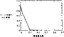
Fig. 9 is the illustrative graph as the energy that is produced by the oscillating magnetic flux system of the function of the confficient of static friction between magnet and the supporting construction thereof;
Figure 10 is the schematic diagram that explanation can be passed through the ultra-low friction of novel ferrofluid lubricant acquisition;
Figure 11 is that magnet is in enclosure and the generalized section of pick-up winding embodiment inside;
Figure 12 is the curve chart with the output voltage of the shown device generation of Figure 11.
Detailed description of the present invention
The invention provides the friction of the ultra low degree between magnet and the supporting construction thereof, non-by supporting construction Useful electric energy is sent in the normal slight motion that departs from horizontal plane and/or the motion on horizontal plane. For example, when this When supporting construction is held in the user's hand or is placed in the coat pocket, walking movement or other normal motions, Such as turning, spring, the motion of the vibration-generating such as bow even get on or off the bus can both be sent useful electric weight at an easy rate, Simultaneously because wave or wind action and the motion that departs from slightly level also can both be used to generating.
In order to make magnet to the motion of its supporting construction high-sensitive response can be arranged, preferably with choice of ferrofluid bearings As the interface between magnet and the supporting construction. Ferrofluid is magnetic or the magnetizable particulate of fine dispersion Dispersion, particulate usually have the size range of 30 to 150 dusts and are dispersed in the carrier of liquid. Magnetic is little Grain is covering surfaces agent alive or dispersant usually. Changeless distance between the Surfactant assurance magnetic particle is with gram The attraction that clothes are caused by Van der Waals for and magnetic interaction is also carried at the skin of capped particulate simultaneously For the chemical composition of coordinating mutually with the chemicals of liquid-carrier and surrounding environment. The ferrite that is used as magnetic particle Provide some physics and chemistry performances with the trivalent iron oxide to ferrofluid, comprised saturation magnetization, viscosity, Magnetic stability and chemical stability. Ferrotec (USA) Corporation of Nashua, New Hampshire The ferrofluid of several types is provided. Relate to ferrofluid preparation patent be summarized in United States Patent (USP) Introduction is arranged in 6056889.
Ferrofluid had been used in electrically driven (operated) system in the past. For example, disclose in No. 5323076 patents A kind of spindle motor of dish, the ball of the electric drive spindle that ferrofluid lubricant is used as rotating in this motor The substitute of bearing. In No. 5452520 patents, the ferrofluid band provides the magnet that slides in dipmeter The motion that supporting, magnet depart from the center is surveyed by Hall element or coil, and is used to be activated at device Coil on each end, these coils return to magnet again its center.
Having done various effort is applied in the generating ferrofluid with to outside system power supply. 4064409 Number patent utilization make its magnetic property that the characteristic of fast-changing ferrofluid take place by changing temperature, by with magnetic Body place a closed loop ferrofluid system around send electric energy to produce a kind of ferrofluid by one Solenoidal from the pumping effect. But, the system of this type need external heat source can not carry out long-range or Portable operation.
The applicant has invented a kind of new method of utilizing ferrofluid in the generating of the power supply of the system outside Blast Furnace Top Gas Recovery Turbine Unit (TRT) itself.This new method is according to the low frictional behavior of ferrofluid, rather than its magnetic characteristic is with variation of temperature.Provide a kind of reciprocating system, thereby magnet produces electric current with respect to the conductive coil motion to induce electromotive force in coil in this system.By use the ferrofluid lubricant of suitably selecting that an extremely low coefficient of friction is provided for magnet, make magnet can respond very slight inclination or respond its package casing to be endowed various translations and to move and generate electricity.Needn't as the motion magnet Blast Furnace Top Gas Recovery Turbine Unit (TRT) that has earlier, rock this device tempestuously or it is kept vertical.
The characteristic of ferrofluid and magnet is relevant.If magnet has low relatively magnetic field, just should use the ferrofluid of relative high magnetic intensity.The common scope in the magnetic field of magnet is about 500-4000 Gauss, and the magnetization of ferrofluid is 50-400 Gauss.
The coefficient of friction of ferrofluid is relevant to its viscosity (measuring (cp) with centipoise) roughly, but is not directly related.For example, viscosity is that the ferrofluid of 300cp has been found and has about 0.015 confficient of static friction, EFH1 ferrofluid from Ferrotec (USA) Corporation has the viscosity of the 6cp order of magnitude and about 0.002 confficient of static friction, but has the water-based ferrofluid of 5cp viscosity to be found to have about 0.01 confficient of static friction.The higher coefficient of friction of forming for some low viscosities is by owing to the surface tension relevant with water-based solvent.
Be used for preferred ferrofluid of the present invention and have substantially viscosity,, and reach the ultralow confficient of static friction of 0.0008-0.0012 scope in fact less than 2cp less than 5cp.When device axis leaving water flat dip only about 0.07 was spent, such coefficient of friction was enough sensitive for the magnet that begins to slide in the device.Ferrofluid this and that other are suitable is formed and is being entitled as " Mechanical Translator with Ultra Low FrictionFerrofluid Bearings (mechanical transla-tor with ultra-low friction choice of ferrofluid bearings) ", discuss in the patent application of awaiting the reply jointly 10/078132 series number of applying on the same day with the present invention by applicant Jeffray T.Cheung, this patent application of awaiting the reply is jointly also given assignee InnovativeTechnology Licensing of the present invention by transfer, LLC, the content of this application is incorporated by reference herein hereby.This composition comprises two to four parts of isoparaffin acid of EFH1 light mineral oil ferrofluid, mixed of a Ferrotec (USA) Corporation, stirs 24 hours mixture.The suitable source of isoparaffin acid is from the Isopar 6 of Exxon MobilChemical Corp. and Isopar M.Also can use undiluted EFH1 ferrofluid.Undiluted EFH1 is made up of the bigger weight supporting ability of forming than dilution, but for great majority are used, dilutes this composition and still keep sufficient weight supporting ability.Also can use confficient of static friction until other ferrofluids of about 0.02, EMG805 type such as Ferrotec (USA) Corporation, the water-based ferrofluid of a kind of confficient of static friction about 0.01 and the about 5cp of viscosity is because still can reach 75% of zero friction system with the available power output of 0.01 confficient of static friction.Current, EMG805 ratio of components EFH1 forms much expensive, but the load bearing value is low slightly.
Fig. 1 has illustrated the application of the present invention in environmental sensor.A movable permanent magnet 2 is inclusive in the nonmagnetic package casing 4, and magnet 6 and 8 is in the relative two ends of package casing, and is relative with 2 one-tenth axial poles of center magnet.Like this, the motion magnet all is identical magnetic pole with each end that the end magnet faces one another, and therefore when the approaching end of motion magnet magnet, the kinetic energy of motion magnet is converted into potential energy, and being ostracised when it transforms the energy that reverses again when the end magnet leaves.Ferrofluid in package casing is inhaled the pearl 10,12 that centers on the end magnetic pole of magnet toward the magnetic pole of magnet 2 with formation naturally.This provides the lubricated of ultra-low friction, makes magnet 2 motion freely in package casing, and the supporting construction of magnet is provided.Magnet will respond inclination or the moving horizontally with respect to package casing of package casing that package casing leaves level and move.
The conductive coil 14 that is generally copper is around being that part of coiling that crosses in the path of magnet 2 between its end magnet 6 and 8 of package casing at least.Magnet produces electric current because of the moving magnetic field sectioned coil of magnet with respect to the motion of its package casing in coil 14.Hold the repelling effect of magnet 6 and 8 to limit the motion of motion magnet 2, but have buffering effect, prevent the hard end magnet of motion magnet bump.Because magnetic repulsion is with 1/d
4Change, d is two distances between the magnet herein, and when the motion magnet was held magnet near one, repulsive force increased very fastly.
The motion that gives package casing 4 moves back and forth magnet 2 back and forth between end magnet 6 and 8.According to specific application, the motion of package casing can be single shaft to motion, along the reciprocating motion of the longitudinal axis, pivoted, rotation or other more complicated forms of motion around central shaft.When moving back and forth, magnet 2 in coil 14, produces the AC electric current.In the embodiment that Fig. 1 shows, this electric current is by bridge circuit 16 rectifications and be used to battery 18 chargings, and this battery 18 provides power supply for environmental sensor 20, and this transducer can detect the one or more environmental conditions such as temperature, pressure, gas, radiation etc.In order on remote location, to set up transducer, the information of the relevant detected condition of a reflector 22 emissions can be set, this reflector is equally by battery 18 powered operation.Perhaps, but transducer 20 real-time workings, direct output power supply and cancellation battery 18 from coil 14 or bridge circuit 16.
Fig. 2 has illustrated the application of the present invention to alert anxious reflector.Drawn among the figure except this embodiment middle-end magnet substitute with spring 24,26 outside the ferrofluid identical Blast Furnace Top Gas Recovery Turbine Unit (TRT) of lubricating with Fig. 1.This kind form stops action for the motion magnet provides mild, because the increase of elastic force is linear basically rather than as holds the magnet and 1/d
4Proportional, but shortcoming is also arranged, the entity contact all takes place at the end points of its each motion in reciprocal magnet, so may damage magnet because of the contact that repeats after a period of time.
The output of coil is connected to rectification bridge circuit 28, and rectification is output as the battery charge to alert anxious reflector 32 power supplies.The application of this system comprised as Fig. 6 and Fig. 7 being used for of illustrating respectively launches the Blast Furnace Top Gas Recovery Turbine Unit (TRT) of wave power supply of alert anxious signal and the system that is used for the wind power supply of land transmission at sea.
Fig. 3 has illustrated a kind of possible configuration that the package casing 4 of the passage 34 with definite shape is set in the wall of the circular cross-section package casing of other modes, the size of magnet 2 is slided it but can be avoided horizontal motion in this passage.This is of great use for the application that package casing will stand motion horizontal and in the plane of magnet movement, helps magnet is restricted in the motion longitudinally.
The present invention has a lot of application, wherein several explanations in this article.Fig. 4 has illustrated that the present invention is used to the example of portable photoflash lamp.Aforesaid Blast Furnace Top Gas Recovery Turbine Unit (TRT) 36 is set in the photoflash lamp shell 38, and lighting bulb 40 at one end remains on the bulb contact 42 also luminous by a transparent panel 44, and transparent panel can be removed so that install and remove bulb by laying down bolt.Similar with aforesaid other embodiment, Blast Furnace Top Gas Recovery Turbine Unit (TRT) 36 provides AC output, and AC exports by bridge circuit 46 rectifications, and the output after the rectification is to battery 48 chargings that are connected with bulb contact 42 in the line.Also have, if wish flash of light operation in real time then can omit battery, in any application of the present invention, if wish directly by the work of AC signal then can omit the bridge path rectification circuit.
Fig. 5 has shown a kind of modification, and the longitudinal axis of photoflash lamp shell 38 ' is along a camber line bending rather than linear in this modification; It is also contemplated that much other ergonomic designs.This photoflash lamp is held in the staff 46, and the camber line of the swing of arm was consistent when the curvature of its design was walked with the people.Motion stably is provided between magnet and package casing thereof during normal walking movement like this.
Fig. 6 has illustrated the Blast Furnace Top Gas Recovery Turbine Unit (TRT) by the wave motion operation.This system is for powering to alert anxious reflector, and submerged cable relay station and other need be of great use with the maritime applications of the unavailable power supply of additive method.In the illustrated embodiment, a pair of unsteady tubular enclosure 48,50 laterally connects mutually in the middle.Hold an aforesaid Blast Furnace Top Gas Recovery Turbine Unit (TRT) and any relevant electronic device in each package casing.When being floated in the water 52, two Blast Furnace Top Gas Recovery Turbine Unit (TRT) will be more stable and sensitiveer to wave action than single Blast Furnace Top Gas Recovery Turbine Unit (TRT) on different directions.Their output generation combined together is than with single Blast Furnace Top Gas Recovery Turbine Unit (TRT) stable power more.Can also be with other configurations of many package casings or single package casing, such as linear array, cubical array, triangle and other geometries.
But Fig. 7 has illustrated the similar wind power generation plant that moves and generate electricity by wind that is suspended in the maritime affairs Blast Furnace Top Gas Recovery Turbine Unit (TRT) of Fig. 6 in the air.Supporting construction 54 comprises this device is suspended on the suspension that it can be moved by wind.Also have, Blast Furnace Top Gas Recovery Turbine Unit (TRT) is shown as a pair of tubulose Blast Furnace Top Gas Recovery Turbine Unit (TRT) 58,60 that laterally connects mutually in the middle, and the two ends of pipe are attached on the supporting construction.Can also add wind vane or other modifies article and makes it sensitiveer to wind with the windward side that increases Blast Furnace Top Gas Recovery Turbine Unit (TRT).Along with package casing departs from the swing of level because of the wind-force effect, the magnet that is held moves and produces electric energy output along pipe.
Fig. 8 has shown the application of the present invention on the cell phone on coat pocket that can place people or the belt buckle 62; For the purpose of simplifying, the coil on magnet package casing 4 does not show.To be arranged in the shell of phone as battery in above-mentioned other application of the present invention and relevant rectification circuit thereof.
Therefore magnet package casing 4 is supported in the cell phone 62, has the orientation of basic horizontal in phone uprightly is placed on user's coat pocket or when hanging on the belt buckle.The autokinesis that the present invention reached can obtain the power supply output of 0.4 wattage magnitude, and this motion of following for normal walking is easy to reach, and about 0.2 watt of the average power that typical cell phone consumes at present.Like this, cell phone and similar device become important use of the present invention.
The present invention also has many other application, comprises portable, portable or other are vulnerable to the device of motion effect.For example, generator as herein described can be installed on the axletree of automobile or other vehicles to catch vibrations and be used to the air pressure probe generating that is embedded in the tire from vehicle movement.Pressure information can be passed to driver's display so that the alarm of low pressure or high-pressure situations to be provided.
The acquisition of the ultra low friction interface between the wall of motion magnet and package casing thereof is a successful implementation importance of the present invention.The curve display of Fig. 9 the electric energy that is producing on the standardized basis for the package casing of the horizontal alignment that is subjected to the motion effect that usually in walking, carries as the relative populations of the function of the confficient of static friction between magnet and the package casing.Can see that under 0.1 confficient of static friction, electric energy output quickly falls to low-down level from no friction system, after this, along with coefficient of friction greater than about 0.2, electric energy more little by little descends until not exporting fully.Adopting preferably provides about 0.01 or the ferrofluid of littler ultralow confficient of static friction, and the present invention can reach near best electric energy output.
Figure 10 has illustrated with the accessible ultra-low friction of specific ferrofluid.Magnet 64 is shown and is supported on the substrate 66, and substrate 66 is supported on the stayed surface 68 of a level then.Choice of ferrofluid bearings 70 provides a ultra low friction interface between magnet 64 and substrate 66.The orientation of magnet is shown as its magnetic axis 72 fundamental sum substrates 66 transverse intersection.
Adopt suitable ferrofluid 16, between magnet and substrate, can obtain the friction of ultra low degree, make magnet stand the super-sensitive response of generation the inclination of substrate or the translation that is applied on the magnet.Confficient of static friction is measured like this, begin to slide until magnet by an end that departs from horizontal surface 68 raising substrates 66 along substrate, determine that the substrate displacement departs from the critical angle that level begins to slide, substrate is put back to level, lift its other end, begin in the opposite direction to slide until magnet, determine that the substrate displacement departs from the critical angle that level begins to slide on this direction, average then these two critical angles.Because mix the acid of aforesaid EFH1/ isoparaffin, magnet be significantly smaller than 1 degree in addition more less than 10 minutes average critical angle under begin to slide.In fact find, be about 0.07 degree from the critical angle of horizontal static position displacement.
Though show and narrated several embodiments of the present invention, for the skilled personnel in present technique field can also make many in other modification and implementation method.For example, do not adopt aforesaid mobile package casing, but package casing can be held in position, magnet moves as piston.Also have, alternate magnets places the shell interior loop outside shell, and these elements can be provided with conversely, and coil at interior and magnet outside.This kind modification illustrates that in Figure 11 the magnetic field toroidal magnet 74 consistent with its axis is free to slide among the figure on choice of ferrofluid bearings 78 on pipe 76.Electric apparatus coil 80 is positioned at pipe.When magnet on pipe planar coil near when sliding, electric energy output is produced by coil and is detected by voltmeter 82.This modification can itself form be used, or and is coupled around the additional exterior loop of magnet.
The signal that produces with an example of the design of Figure 11 shows in Figure 12.The coil of 268 circles is placed in the pipe of 1.054cm external diameter 0.762cm internal diameter.Magnet is a pottery dish, and the opening of 1.27cm diameter passes its center, falls from the height of 40cm.Result's AC voltage is exported the peak value of the 160mV that has an appointment.
Correspondingly, will only limit the scope of the invention according to attached claim.
Claims (67)
- One kind to be used for the machine movement conversion be the energy conversion device of electric energy, this device comprises:Coil andA magnetic devices, this magnetic devices comprise that one is arranged to move back and forth with the magnet of generation with respect to the moving magnetic field of described coil,Coupling was from the electric energy of described device output when described coil was configured to relative motion between described magnet and coil,Wherein said device has the critical angle from the horizontal static position displacement less than 1 degree.
- 2. energy conversion device as claimed in claim 1 is characterized in that wherein said critical angle was less than 10 minutes.
- 3. energy conversion device as claimed in claim 1 further comprises the choice of ferrofluid bearings that supports described magnet.
- 4. energy conversion device as claimed in claim 3 is characterized in that wherein said magnetic devices further comprises the polymer passage of surrounding described magnet.
- 5. energy conversion device as claimed in claim 1 is characterized in that this energy conversion device is draped, by the application campaign of perturbed force.
- 6. energy conversion device as claimed in claim 1 is characterized in that, described device comprises a sealed tube that holds described magnet.
- 7. Blast Furnace Top Gas Recovery Turbine Unit (TRT) comprises:A conductor,A supporting construction,One be subjected to the restriction of described supporting construction with respect to the magnet of described conductor motion andOne is arranged on the ferrofluid that low friction interface is provided between described magnet and the supporting construction,Described conductor makes the relative motion between magnet and the conductor produce the signal of telecommunication in described conductor with respect to described magnet setting.
- 8. Blast Furnace Top Gas Recovery Turbine Unit (TRT) as claimed in claim 7 comprises that further a pair of end magnet also relative with described magnet poles in the relative both sides of described magnet is to limit the motion of described magnet.
- 9. Blast Furnace Top Gas Recovery Turbine Unit (TRT) as claimed in claim 7 is characterized in that described supporting construction comprises the passage that is used for described magnet.
- 10. Blast Furnace Top Gas Recovery Turbine Unit (TRT) as claimed in claim 7 is characterized in that, wherein said supporting construction is configured to make the motion of this supporting construction basic horizontal of described magnet response and moves.
- 11. Blast Furnace Top Gas Recovery Turbine Unit (TRT) as claimed in claim 7 is characterized in that, wherein said supporting construction is configured to be carried by the people, described magnet response people's motion and reciprocating motion.
- 12. Blast Furnace Top Gas Recovery Turbine Unit (TRT) as claimed in claim 7 is characterized in that, wherein said ferrofluid has the viscosity less than 5 centipoises.
- 13. Blast Furnace Top Gas Recovery Turbine Unit (TRT) as claimed in claim 7 is characterized in that, wherein said ferrofluid comprises the light mineral oil medium of mixed with isoparaffinic acid.
- 14. Blast Furnace Top Gas Recovery Turbine Unit (TRT) as claimed in claim 1 further comprises the circuit from the electric energy of described conductor of coupling from the output of described Blast Furnace Top Gas Recovery Turbine Unit (TRT).
- 15. a Blast Furnace Top Gas Recovery Turbine Unit (TRT) comprises:A magnet that is restricted with respect to the package casing motion,One be arranged between described magnet and the package casing with ferrofluid that low friction interface is provided andA conductor coils that is provided with respect to described magnet, described like this magnet produces the signal of telecommunication with respect to the motion of coil in described coil.
- 16. Blast Furnace Top Gas Recovery Turbine Unit (TRT) as claimed in claim 15 is characterized in that, wherein said coil is along the part setting of moving and crossing of the described magnet of described package casing.
- 17. Blast Furnace Top Gas Recovery Turbine Unit (TRT) as claimed in claim 15 is characterized in that, wherein said magnet with respect to described package casing setting to provide air flowing access between the opposite flank at magnet when the magnet movement.
- 18. Blast Furnace Top Gas Recovery Turbine Unit (TRT) as claimed in claim 17, it is characterized in that, wherein said magnet is in described package casing and occupy area less than the totality cross-sectional area of described package casing, provides around the described air flowing access of the excircle of described magnet.
- 19. Blast Furnace Top Gas Recovery Turbine Unit (TRT) as claimed in claim 15 is characterized in that, wherein said package casing is roughly tubular.
- 20. Blast Furnace Top Gas Recovery Turbine Unit (TRT) as claimed in claim 15 is characterized in that, comprises that further a pair of end magnet also relative with described magnet poles in the relative both sides of described magnet is to limit the motion of described magnet.
- 21. Blast Furnace Top Gas Recovery Turbine Unit (TRT) as claimed in claim 15 is characterized in that, wherein said supporting construction is configured to make the motion of this supporting construction basic horizontal of described magnet response and moves with respect to this supporting construction.
- 22. Blast Furnace Top Gas Recovery Turbine Unit (TRT) as claimed in claim 15 is characterized in that, wherein said supporting construction is configured to be carried by the people, described magnet response people's motion and with respect to this supporting construction reciprocating motion.
- 23. Blast Furnace Top Gas Recovery Turbine Unit (TRT) as claimed in claim 22 is characterized in that, wherein said package casing is crooked.
- 24. Blast Furnace Top Gas Recovery Turbine Unit (TRT) as claimed in claim 15, it is characterized in that, wherein said package casing is inclusive in the unsteady outer package, realizes the relative motion between described magnet and the coil when described outer package floats on the liquid and suffers wave action, produces the signal of telecommunication in described coil.
- 25. Blast Furnace Top Gas Recovery Turbine Unit (TRT) as claimed in claim 15 is characterized in that, further comprises a suspension that hangs described package casing, package casing moves and makes described magnet response wind that the promotion of package casing is produced the signal of telecommunication like this.
- 26. Blast Furnace Top Gas Recovery Turbine Unit (TRT) as claimed in claim 15 is characterized in that, wherein said ferrofluid has the viscosity less than 5 centipoises.
- 27. Blast Furnace Top Gas Recovery Turbine Unit (TRT) as claimed in claim 15 is characterized in that, wherein said ferrofluid comprises the light mineral oil medium of mixed with isoparaffinic acid.
- 28. Blast Furnace Top Gas Recovery Turbine Unit (TRT) as claimed in claim 15 further comprises the circuit from the electric energy of described conductor of coupling from the output of described Blast Furnace Top Gas Recovery Turbine Unit (TRT).
- 29. a batter-charghing system comprises:A conductor,A battery contact point,A supporting construction,One by the restriction of described supporting construction with respect to the magnet of described conductor motion andOne is arranged on the ferrofluid that low friction interface is provided between described magnet and the supporting construction,Described conductor makes the relative motion between magnet and the conductor produce battery-charge signal in described conductor with respect to described magnet setting, and described conductor is connected to described battery-charge signal is provided on the described battery contact point.
- 30. batter-charghing system as claimed in claim 29 further comprises a rectification circuit, described conductor is connected to described battery-charge signal is provided on the described battery contact point by described rectification circuit.
- 31. batter-charghing system as claimed in claim 29 is characterized in that, wherein said ferrofluid has the viscosity less than 5 centipoises.
- 32. batter-charghing system as claimed in claim 31 is characterized in that, wherein said ferrofluid comprises the light mineral oil medium of mixed with isoparaffinic acid.
- 33. a batter-charghing system comprises:A coil,Battery contact point andA magnetic devices, this magnetic devices comprise that one is arranged to move back and forth with the magnet of generation with respect to the moving magnetic field of described coil,Described coil is configured to according to the relative motion between described magnet and the coil couple electrical energy be arrived described battery contact point,Wherein said device has the critical angle from the horizontal static position displacement less than 1 degree.
- 34. batter-charghing system as claimed in claim 33 is characterized in that, wherein said critical angle was less than 10 minutes.
- 35. an electric operating means comprises:A shell of being arranged to be carried,Electrical pickoff in described shell,A conductor,Supporting construction in described shell,One by the restriction of described supporting construction with respect to the magnet of described conductor motion andOne is arranged on the ferrofluid that low friction interface is provided between described magnet and the supporting construction,Described conductor makes the relative motion between magnet and the conductor produce the signal of telecommunication in described conductor with respect to described magnet setting, and described conductor is connected to described pumping signal is provided on the described contact point.
- 36. device as claimed in claim 35 is characterized in that, wherein said ferrofluid has the viscosity less than 5 centipoises.
- 37. device as claimed in claim 35 is characterized in that, wherein said ferrofluid comprises the light mineral oil medium of mixed with isoparaffinic acid.
- 38. an electric operating means comprises:A coil,A shell of being arranged to be carried,Electrical pickoff in described shell,Magnetic devices in described shell, this magnetic devices comprise that one is arranged to move back and forth with the magnet of generation with respect to the moving magnetic field of described coil,Described coil is configured to according to the relative motion between described magnet and the coil couple electrical energy be arrived described contact point,Wherein said device has the critical angle from the horizontal static position displacement less than 1 degree.
- 39. device as claimed in claim 38 is characterized in that, wherein said critical angle was less than 10 minutes.
- 40. an EMS comprises:An environmental sensor of being arranged to produce the output signal of pointing out environmental condition,A conductor,A supporting construction,One by the restriction of described supporting construction with respect to the magnet of described conductor motion andOne is arranged on the ferrofluid that low friction interface is provided between described magnet and the supporting construction,Described conductor is with respect to described magnet setting, makes relative motion between magnet and the conductor produce the pumping signal of described transducer.
- 41. EMS as claimed in claim 40 is characterized in that, described transducer comprises a reflector by described pumping signal power supply, is used to launch the signal of pointing out described environmental condition.
- 42. EMS as claimed in claim 40 is characterized in that, described transducer comprises a battery, and described conductor connects into described pumping signal is provided to described battery as battery-charge signal.
- 43. EMS as claimed in claim 40 is characterized in that, described conductor connects into provides described pumping signal with the described transducer of real-time excitation.
- 44. EMS as claimed in claim 40 further comprises a rectification circuit, described conductor connects into described pumping signal is provided to described transducer by described rectification circuit.
- 45. EMS as claimed in claim 40 is characterized in that, wherein said ferrofluid has the viscosity less than 5 centipoises.
- 46. EMS as claimed in claim 40 is characterized in that, wherein said ferrofluid comprises the light mineral oil medium of mixed with isoparaffinic acid.
- 47. an EMS comprises:An environmental sensor of being arranged to produce the output signal of pointing out environmental condition,Coil andA magnetic devices, this magnetic devices comprise that one is arranged to move back and forth with the magnet of generation with respect to the moving magnetic field of described coil,Described coil is configured to according to the relative motion between described magnet and the coil couple electrical energy be arrived described transducer,Wherein said device has the critical angle from the horizontal static position displacement less than 1 degree.
- 48. EMS as claimed in claim 47 is characterized in that, wherein said critical angle was less than 10 minutes.
- 49. the anxious emission system of police comprises:The anxious signal projector of police,A conductor,A supporting construction,One by the restriction of described supporting construction with respect to the magnet of described conductor motion andOne is arranged on the ferrofluid that low friction interface is provided between described magnet and the supporting construction,Described conductor is with respect to described magnet setting, makes relative motion between magnet and the conductor produce the pumping signal of described reflector.
- 50. the anxious emission system of police as claimed in claim 49 is characterized in that, described reflector comprises a battery, and described conductor connects into described pumping signal is provided to described battery as battery-charge signal.
- 51. the anxious emission system of police as claimed in claim 49 is characterized in that, described conductor connects into provides described pumping signal with the described reflector of real-time excitation.
- 52. the anxious emission system of police as claimed in claim 49 further comprises a rectification circuit, described conductor connects into described pumping signal is provided to described reflector by described rectification circuit.
- 53. the anxious emission system of police as claimed in claim 49 is characterized in that wherein said ferrofluid has the viscosity less than 5 centipoises.
- 54. the anxious emission system of police as claimed in claim 49 is characterized in that wherein said ferrofluid comprises the light mineral oil medium of mixed with isoparaffinic acid.
- 55. the anxious emission system of police comprises:The anxious signal projector of police,Coil andA magnetic devices, this magnetic devices comprise that one is arranged to move back and forth with the magnet of generation with respect to the moving magnetic field of described coil,Described coil is configured to according to the relative motion between described magnet and the coil couple electrical energy be arrived described reflector,Wherein said device has the critical angle from the horizontal static position displacement less than 1 degree.
- 56. the anxious emission system of police as claimed in claim 55 is characterized in that wherein said critical angle was less than 10 minutes.
- 57. a cell phone system comprises:A cell phone,A conductor,One is connected to described cellular supporting construction,One by the restriction of described supporting construction with respect to the magnet of described conductor motion andOne is arranged on the ferrofluid that low friction interface is provided between described magnet and the supporting construction,Described conductor makes the relative motion between magnet and the conductor produce described cellular pumping signal with respect to described magnet setting.
- 58. cell phone system as claimed in claim 57 is characterized in that, described reflector comprises a battery, and described conductor connects into described pumping signal is provided to described battery as battery-charge signal.
- 59. cell phone system as claimed in claim 57 is characterized in that, wherein said ferrofluid has the viscosity less than 5 centipoises.
- 60. cell phone system as claimed in claim 57 is characterized in that, wherein said ferrofluid comprises the light mineral oil medium of mixed with isoparaffinic acid.
- 61. a cell phone system comprises:A cell phone,Coil andA magnetic devices, this magnetic devices comprise that one is arranged to move back and forth with the magnet of generation with respect to the moving magnetic field of described coil,Described coil is configured to according to the relative motion between described magnet and the coil couple electrical energy be arrived described cell phone,Wherein said device has the critical angle from the horizontal static position displacement less than 1 degree.
- 62. cell phone system as claimed in claim 61 is characterized in that, wherein said critical angle was less than 10 minutes.
- 63. the method for a generating comprises:For magnet provides a low friction choice of ferrofluid bearings,Make magnet in described supporting reciprocating motion andUtilize the motion generating of magnet.
- 64. the method as claim 63 is characterized in that, wherein said ferrofluid has the viscosity less than 5 centipoises.
- 65., it is characterized in that wherein said ferrofluid comprises the light mineral oil medium of mixed with isoparaffinic acid as the described method of claim 63.
- 66. the method for a generating comprises:A magnetic devices is provided, and this magnetic devices comprises that one is arranged to move back and forth and has a magnet from the critical angle of horizontal static position displacement less than 1 degree,Make this magnet with respect to a coil reciprocating motion with produce a reciprocating magnetic field andOn described coil, produce the signal of telecommunication with described magnetic field.
- 67., it is characterized in that wherein said critical angle was less than 10 minutes as the described method of claim 66.
Applications Claiming Priority (3)
| Application Number | Priority Date | Filing Date | Title |
|---|---|---|---|
| US10/078,724 US6812583B2 (en) | 2002-02-19 | 2002-02-19 | Electrical generator with ferrofluid bearings |
| US10/078,724 | 2002-02-19 | ||
| PCT/US2003/004896 WO2003071663A1 (en) | 2002-02-19 | 2003-02-18 | Electrical generator with ferrofluid bearings |
Publications (2)
| Publication Number | Publication Date |
|---|---|
| CN1647351A true CN1647351A (en) | 2005-07-27 |
| CN1647351B CN1647351B (en) | 2011-06-29 |
Family
ID=27732890
Family Applications (1)
| Application Number | Title | Priority Date | Filing Date |
|---|---|---|---|
| CN038087588A Expired - Fee Related CN1647351B (en) | 2002-02-19 | 2003-02-18 | Electrical generator with ferrofluid bearings |
Country Status (4)
| Country | Link |
|---|---|
| US (2) | US6812583B2 (en) |
| CN (1) | CN1647351B (en) |
| AU (1) | AU2003222224A1 (en) |
| WO (1) | WO2003071663A1 (en) |
Cited By (3)
| Publication number | Priority date | Publication date | Assignee | Title |
|---|---|---|---|---|
| CN102666146A (en) * | 2009-10-30 | 2012-09-12 | 倍耐力轮胎股份公司 | Method for generating electric energy in a tyre |
| CN105790342A (en) * | 2014-12-22 | 2016-07-20 | 张迎春 | Magnetic fluid motion power generation-based general charging device |
| CN109238699A (en) * | 2018-10-19 | 2019-01-18 | 南昌工程学院 | A kind of lubrication test macro of the adjustable magnetic fluid bearing of viscosity |
Families Citing this family (91)
| Publication number | Priority date | Publication date | Assignee | Title |
|---|---|---|---|---|
| US7408453B2 (en) * | 2001-02-16 | 2008-08-05 | Automotive Technologies International, Inc. | Wheel-mounted tire pumping and energy generating system and method |
| US20070205881A1 (en) * | 2000-09-08 | 2007-09-06 | Automotive Technologies International, Inc. | Energy Harvesting Systems and Methods for Vehicles |
| US7749089B1 (en) | 1999-02-26 | 2010-07-06 | Creative Kingdoms, Llc | Multi-media interactive play system |
| US7878905B2 (en) | 2000-02-22 | 2011-02-01 | Creative Kingdoms, Llc | Multi-layered interactive play experience |
| US6761637B2 (en) | 2000-02-22 | 2004-07-13 | Creative Kingdoms, Llc | Method of game play using RFID tracking device |
| US7445550B2 (en) | 2000-02-22 | 2008-11-04 | Creative Kingdoms, Llc | Magical wand and interactive play experience |
| US7066781B2 (en) | 2000-10-20 | 2006-06-27 | Denise Chapman Weston | Children's toy with wireless tag/transponder |
| US20070066396A1 (en) | 2002-04-05 | 2007-03-22 | Denise Chapman Weston | Retail methods for providing an interactive product to a consumer |
| US6967566B2 (en) | 2002-04-05 | 2005-11-22 | Creative Kingdoms, Llc | Live-action interactive adventure game |
| US7285868B2 (en) * | 2002-07-25 | 2007-10-23 | Kitchener Clark Wilson | Apparatus and method for energy generation within a tire |
| US9446319B2 (en) | 2003-03-25 | 2016-09-20 | Mq Gaming, Llc | Interactive gaming toy |
| US20040222638A1 (en) * | 2003-05-08 | 2004-11-11 | Vladimir Bednyak | Apparatus and method for providing electrical energy generated from motion to an electrically powered device |
| US7009310B2 (en) * | 2004-01-12 | 2006-03-07 | Rockwell Scientific Licensing, Llc | Autonomous power source |
| US7710460B2 (en) * | 2004-07-21 | 2010-05-04 | Hewlett-Packard Development Company, L.P. | Method of compensating for an effect of temperature on a control system |
| US7679647B2 (en) * | 2004-07-21 | 2010-03-16 | Hewlett-Packard Development Company, L.P. | Flexible suspension for image stabilization |
| US7710459B2 (en) * | 2004-07-21 | 2010-05-04 | Hewlett-Packard Development Company, L.P. | Ferrofluid suspension for image stabilization |
| WO2006010203A1 (en) * | 2004-07-28 | 2006-02-02 | Kinergi Pty Ltd | Motion activated power source |
| US7333783B2 (en) | 2005-04-14 | 2008-02-19 | Teledyne Licensing, Llc | Mobile device with manually operated power source |
| US7205677B2 (en) * | 2005-05-19 | 2007-04-17 | Incelex, Llc | Automated motion provider for self powered cell phones |
| US7576454B2 (en) * | 2005-05-23 | 2009-08-18 | Ciiis, Llc | Multiple magnet coil in gap generator |
| US7439024B2 (en) * | 2005-06-01 | 2008-10-21 | The United States Of America As Represented By The Department Of Veterans Affairs | Methods and kits for diagnosing or monitoring autoimmune and chronic inflammatory diseases |
| KR100635405B1 (en) * | 2005-06-10 | 2006-10-19 | 한국과학기술연구원 | Micro power generator |
| US7525203B1 (en) * | 2005-08-11 | 2009-04-28 | Jeffrey Racho | Back-up electric power generator for electronic components attached to automatic firearms |
| US7148583B1 (en) * | 2005-09-05 | 2006-12-12 | Jeng-Jye Shau | Electrical power generators |
| US20080174281A1 (en) * | 2005-09-05 | 2008-07-24 | Albert Shau | Electrical power generators |
| US20070076325A1 (en) * | 2005-09-20 | 2007-04-05 | Nokia Corporation | Apparatus for indicating a state of a device |
| CN101604880B (en) * | 2005-09-23 | 2011-07-27 | 中国人民解放军国防科学技术大学 | Speed-up generating device of portable electronic equipment based on rotatory inertia block |
| JP4072551B2 (en) * | 2005-11-09 | 2008-04-09 | ファナック株式会社 | Processing equipment |
| US7245042B1 (en) * | 2005-11-25 | 2007-07-17 | Simnacher Larry W | Auxiliary wind energy generation from a wind power generation apparatus |
| US7327046B2 (en) * | 2005-12-23 | 2008-02-05 | Alexander Benjamin Biamonte | Kinetic energy system and apparatus for charging portable batteries |
| WO2007121367A2 (en) * | 2006-04-13 | 2007-10-25 | Ciiis. Llc | Generator for a portable device having a reciprocating coil system |
| WO2007121382A2 (en) * | 2006-04-14 | 2007-10-25 | Ciiis, Llc | Power generator having a plurality of arranged power generator units |
| TWM306423U (en) * | 2006-04-26 | 2007-02-11 | Liung Feng Ind Co Ltd | Multi-magnetic-poles power generating apparatus |
| US20090179430A1 (en) * | 2006-06-16 | 2009-07-16 | Energy Recovery Technology, Inc. | Energy recovery system |
| US7479715B2 (en) * | 2006-08-14 | 2009-01-20 | Incelex, Llc | Omnidirectional electrical generators |
| US7482706B2 (en) * | 2006-08-25 | 2009-01-27 | Honda Motor Co., Ltd. | Engine-driven work machine system |
| US20080084072A1 (en) * | 2006-10-04 | 2008-04-10 | Incelex, Llc | Moving Coil Electrical Generators |
| US8035245B1 (en) * | 2006-12-28 | 2011-10-11 | Simnacher Larry W | Windpower generator apparatus with auxiliary generators |
| US7605482B2 (en) * | 2007-01-08 | 2009-10-20 | Veryst Engineering Llc | Method and apparatus for energy harvesting using energy storage and release |
| US7498682B2 (en) * | 2007-03-07 | 2009-03-03 | Aaron Patrick Lemieux | Electrical energy generator |
| US20080218128A1 (en) * | 2007-03-08 | 2008-09-11 | Leo Hipom Kim | Self-generation type charging battery assembly |
| US7498681B1 (en) * | 2007-03-21 | 2009-03-03 | Sandia Corporation | Mechanical vibration to electrical energy converter |
| US7727090B2 (en) | 2007-06-05 | 2010-06-01 | Richard Alva Gant | Training bat with visual feedback of proper swing |
| US7554215B1 (en) * | 2007-07-03 | 2009-06-30 | Paul Caragine | Generator and method for generating electricity from subsurface currents |
| JP2009081966A (en) * | 2007-09-27 | 2009-04-16 | Sanyo Electric Co Ltd | Electronic equipment |
| JP2009112069A (en) * | 2007-10-26 | 2009-05-21 | Sanyo Electric Co Ltd | Electronic equipment |
| US7906861B2 (en) * | 2007-11-28 | 2011-03-15 | Schlumberger Technology Corporation | Harvesting energy in remote locations |
| US8217523B2 (en) | 2007-12-07 | 2012-07-10 | Veryst Engineering Llc | Apparatus for in vivo energy harvesting |
| US20090212645A1 (en) * | 2008-02-27 | 2009-08-27 | Infineon Technologies Ag | Electronic device for harvesting energy |
| US8688224B2 (en) * | 2008-03-07 | 2014-04-01 | Tremont Electric, Inc. | Implantable biomedical device including an electrical energy generator |
| US8323187B2 (en) * | 2008-09-19 | 2012-12-04 | Black Mountain Ventures | Noninvasive medical device and method operable in a limited amount of time through a deliberate human motion |
| JP5428297B2 (en) * | 2008-11-10 | 2014-02-26 | ソニー株式会社 | Power generator |
| US8093767B2 (en) * | 2009-05-18 | 2012-01-10 | Brian Marc Pepin | Linear-resonant vibration module |
| US7816799B2 (en) * | 2009-07-22 | 2010-10-19 | Oscilla Power Inc. | Method and device for energy generation |
| US8193781B2 (en) | 2009-09-04 | 2012-06-05 | Apple Inc. | Harnessing power through electromagnetic induction utilizing printed coils |
| US8350394B2 (en) * | 2009-09-30 | 2013-01-08 | Alcatel Lucent | Energy harvester apparatus having improved efficiency |
| US20110121577A1 (en) * | 2009-11-20 | 2011-05-26 | Oscilla Power Inc. | Method and device for energy generation |
| WO2011085091A2 (en) * | 2010-01-06 | 2011-07-14 | Tremont Electric, Llc | Electrical energy generator |
| WO2011085093A2 (en) | 2010-01-06 | 2011-07-14 | Tremont Electric, Llc | Electrical energy generator |
| GB2479926B (en) * | 2010-04-30 | 2016-05-11 | Atherton Nigel | Electricity generator |
| US8723342B2 (en) * | 2010-05-19 | 2014-05-13 | Robert Bosch Gmbh | Wearable generator device |
| KR20130099046A (en) * | 2010-08-11 | 2013-09-05 | 다이나믹 에너지 테크놀러지스, 엘엘씨 | Kinetic energy management system |
| US8552607B2 (en) * | 2010-10-10 | 2013-10-08 | Hong Kong Applied Science and Technology Research Institute Company Limited | Electric power generator with ferrofluid bearings |
| US8975764B1 (en) * | 2010-11-29 | 2015-03-10 | Benyamin Abehasera | Electronic cigarette with integrated charging mechanism |
| DE102010054878A1 (en) * | 2010-12-17 | 2012-06-21 | Samson Aktiengesellschaft | Electropneumatic field device |
| US8736086B2 (en) * | 2011-03-25 | 2014-05-27 | Tai-Her Yang | Reciprocal vibration type power generator equipped with inner columnar and outer annular magnetic members, a power storage device, a rectifying circuit, and a charging circuit |
| US8546964B2 (en) * | 2011-03-25 | 2013-10-01 | Tai-Her Yang | Reciprocal vibration type power generator equipped with a moving inner columnar magnetic block surrounded by at least one coil set, and a moving outer annular magnetic block that surrounds the at least one coil set |
| US9222465B2 (en) * | 2011-04-15 | 2015-12-29 | Northeastern University | Non-rotating wind energy generator |
| US20140246866A1 (en) * | 2011-07-09 | 2014-09-04 | Scott E. Gossler | Micro-motion generator apparatus |
| US9343931B2 (en) | 2012-04-06 | 2016-05-17 | David Deak | Electrical generator with rotational gaussian surface magnet and stationary coil |
| US8975769B2 (en) * | 2012-05-23 | 2015-03-10 | Mountaser Mosaad BAHADIK | Electromagnetic field and current inducing surfboard for repelling sharks |
| US8692397B1 (en) * | 2012-06-13 | 2014-04-08 | The United States Of America As Represented By The Secretary Of The Navy | Mechanism for the conversion of vertical motion to translational or rotational motion |
| US8680698B1 (en) * | 2012-06-13 | 2014-03-25 | The United States Of America As Represented By The Secretary Of The Navy | Self-contained mechanism for the conversion of vertical motion to rotational/translational motion |
| US8692396B1 (en) * | 2012-06-13 | 2014-04-08 | The United States Of America As Represented By The Secretary Of The Navy | Apparatus and method for a hybrid system for harvesting magnetic and electrical energy |
| CN103202587B (en) * | 2013-05-04 | 2014-12-03 | 李笑 | Magnetohydrodynamic power generation mobile phone cover capable of automatically charging Iphone |
| EP3059850A4 (en) * | 2013-10-14 | 2017-06-07 | Sunrising Eco-Friendly Tech. Co., Ltd. | Mobile induction and power-generation device |
| US9780633B2 (en) | 2014-01-28 | 2017-10-03 | Stryde Technologies Inc. | Kinetic energy harvesting methods and apparatus |
| US9331559B2 (en) * | 2014-01-28 | 2016-05-03 | Stryde Technologies Inc. | Kinetic energy harvesting methods and apparatus |
| GB201404861D0 (en) * | 2014-03-18 | 2014-04-30 | Bish Bash Productions Ltd | Percussion instrument |
| US9673683B2 (en) * | 2014-11-07 | 2017-06-06 | David Deak, SR. | Reciprocating magnet electrical generator |
| US9486685B2 (en) | 2015-02-25 | 2016-11-08 | Jay Rambo | Apparatus for providing swing technique feedback |
| EP3341646A1 (en) * | 2015-08-24 | 2018-07-04 | Positively Human Ltd. | Kinetic generator |
| US9617972B1 (en) * | 2015-10-01 | 2017-04-11 | Robert Georges Skaf | Apparatus for converting wave motion on a body of water into electrical power |
| US10720823B1 (en) * | 2016-01-15 | 2020-07-21 | University Of Southern California | Ferrofluid liquid spring with magnets between coils inside an enclosed chamber for vibration energy harvesting |
| DE102016123210A1 (en) * | 2016-12-01 | 2018-06-07 | Centitech Gmbh | voltage generator |
| JP2018191417A (en) * | 2017-05-01 | 2018-11-29 | ヤマウチ株式会社 | Vibration dynamo power generator |
| CN111819770B (en) | 2017-10-30 | 2023-09-19 | 威能科技有限责任公司 | Magnetic momentum transfer type generator |
| US10855158B2 (en) * | 2018-04-19 | 2020-12-01 | Watasensor, Inc. | Magnetic power generation |
| EP3647245A1 (en) * | 2018-10-29 | 2020-05-06 | Otis Elevator Company | Elevator system with energy harvesting device placed at the car |
| WO2021000074A1 (en) * | 2019-06-29 | 2021-01-07 | 瑞声声学科技(深圳)有限公司 | Vibration motor |
| US11581828B2 (en) * | 2021-05-05 | 2023-02-14 | Enervibe Ltd | Electromagnetic vibration and energy harvester having vibrating body, magnets and stationary magnet and hinge |
Family Cites Families (72)
| Publication number | Priority date | Publication date | Assignee | Title |
|---|---|---|---|---|
| US231527A (en) * | 1880-08-24 | Jack for boots and shoes | ||
| US231528A (en) * | 1880-08-24 | Starch ing-machine | ||
| US3083469A (en) | 1960-04-28 | 1963-04-02 | Bogue Elec Mfg Co | Leveling device |
| US3573479A (en) * | 1967-11-17 | 1971-04-06 | Harold F Rieth | Generator flashlight |
| US3554617A (en) | 1969-04-01 | 1971-01-12 | Paul J Weaver | Machine tools slide assembly |
| US3726574A (en) | 1971-08-13 | 1973-04-10 | Litton Systems Inc | Ferrohydrodynamic low-friction bearing with volume compensation |
| US3746407A (en) | 1971-08-13 | 1973-07-17 | Litton Systems Inc | Ferrohydrodynamic low friction bearing |
| US3834775A (en) | 1972-05-26 | 1974-09-10 | Litton Systems Inc | Ferrohydrodynamic low-friction bearing with improved volume compensation and fluid seal |
| US3977739A (en) | 1974-09-06 | 1976-08-31 | Ferrofluidics Corporation | Magnetic ball bearing assembly using ferrolubricants |
| GB1504872A (en) | 1975-02-14 | 1978-03-22 | Strathearn Audio Ltd | Linear bearing for parallel tracking arm |
| US4064409A (en) | 1976-07-28 | 1977-12-20 | Redman Charles M | Ferrofluidic electrical generator |
| US4171818A (en) * | 1977-04-04 | 1979-10-23 | Ferrofluidics Corporation | Dynamic lip seal using ferrofluids as sealant/lubricant |
| FR2407599A1 (en) | 1977-10-27 | 1979-05-25 | Juillet Hubert | Electricity generator with permanent magnet inductor - has magnetic ball moving around inside hollow plastics torus with coil wound around it |
| US4171018A (en) | 1978-03-20 | 1979-10-16 | Deep Oil Technology, Inc. | Tubing hanger assembly and method of landing and locking |
| US4260901A (en) | 1979-02-26 | 1981-04-07 | Woodbridge David D | Wave operated electrical generation system |
| US4356098A (en) | 1979-11-08 | 1982-10-26 | Ferrofluidics Corporation | Stable ferrofluid compositions and method of making same |
| SE421570B (en) | 1980-05-21 | 1982-01-04 | Asea Ab | WITH ISOLERATED COOL BAND WINDING FOR A TRANSFORMER OR REACTOR |
| US4357024A (en) | 1980-11-19 | 1982-11-02 | Ferrofluidics Corporation | Ferrofluid rotary-shaft seal apparatus and method |
| US4430239A (en) | 1981-10-21 | 1984-02-07 | Ferrofluidics Corporation | Ferrofluid composition and method of making and using same |
| US4485024A (en) | 1982-04-07 | 1984-11-27 | Nippon Seiko Kabushiki Kaisha | Process for producing a ferrofluid, and a composition thereof |
| US4814654A (en) | 1984-10-12 | 1989-03-21 | Gerfast Sten R | Stator or rotor based on permanent magnet segments |
| US4604229A (en) | 1985-03-20 | 1986-08-05 | Ferrofluidics Corporation | Electrically conductive ferrofluid compositions and method of preparing and using same |
| US4687596A (en) | 1985-03-20 | 1987-08-18 | Ferrofluidics Corporation | Low viscosity, electrically conductive ferrofluid composition and method of making and using same |
| US4732706A (en) | 1985-03-20 | 1988-03-22 | Ferrofluidics Corporation | Method of preparing low viscosity, electrically conductive ferrofluid composition |
| EP0206516A3 (en) * | 1985-05-21 | 1988-08-10 | Ferrofluidics Corporation | Ferrofluid composition, method of making, and apparatus and method using same |
| US4706498A (en) | 1985-09-23 | 1987-11-17 | Ferrotec, Inc. | Apparatus and method for measuring movement |
| US4734606A (en) | 1985-11-20 | 1988-03-29 | Hajec Chester S | Electric motor with ferrofluid bearing |
| US4709176A (en) * | 1986-07-31 | 1987-11-24 | Ridley William E | Magnetic battery |
| US4898480A (en) | 1987-02-09 | 1990-02-06 | Ferrofluidics Corporation | Compact ferrofluidic electrically conducting sealed bearing |
| US4797013A (en) | 1987-02-09 | 1989-01-10 | Ferrofluidics Corporation | Compact ferrofluidic electrically conducting sealed bearing |
| JPH0727813B2 (en) | 1987-03-03 | 1995-03-29 | 日本精工株式会社 | Magnetic fluid composition |
| US4965864A (en) | 1987-12-07 | 1990-10-23 | Roth Paul E | Linear motor |
| SE8800394L (en) | 1988-02-08 | 1989-08-09 | Skf Nova Ab | SUPERPARAMAGNETIC SCRAPS |
| DE3841011A1 (en) | 1988-12-06 | 1990-06-07 | Lewin Heinz Ulrich | Method and device for contactless movement of bodies |
| US5417507A (en) | 1989-10-07 | 1995-05-23 | Hitachi, Ltd. | Vertical motor, method of manufacturing same, polygon mirror motor using said motor, and bearing device for use in said motor |
| US5175457A (en) | 1991-10-28 | 1992-12-29 | Mechanical Technology Incorporated | Linear motor or alternator plunger configuration using variable magnetic properties for center row and outer rows of magnets |
| US5323076A (en) | 1992-01-24 | 1994-06-21 | Hajec Chester S | Disk spindle motor |
| FR2690793B1 (en) | 1992-05-04 | 1995-12-08 | Moving Magnet Tech | ELECTROMAGNETIC ACTUATOR WITH TWO MOVABLE PARTS OPPOSING PHASES. |
| US5347186A (en) | 1992-05-26 | 1994-09-13 | Mcq Associates, Inc. | Linear motion electric power generator |
| US5341055A (en) * | 1992-08-07 | 1994-08-23 | Roche Robert J | Combination reciprocating motor and inverter |
| US5376862A (en) | 1993-01-28 | 1994-12-27 | Applied Materials, Inc. | Dual coaxial magnetic couplers for vacuum chamber robot assembly |
| US5673721A (en) | 1993-10-12 | 1997-10-07 | Alcocer; Charles F. | Electromagnetic fluid conditioning apparatus and method |
| US5358648A (en) | 1993-11-10 | 1994-10-25 | Bridgestone/Firestone, Inc. | Spin finish composition and method of using a spin finish composition |
| CN1106960A (en) * | 1994-02-08 | 1995-08-16 | 周天宝 | Magnetohydrodynamic electric machine |
| US5452520A (en) | 1994-03-14 | 1995-09-26 | Ferrofluidics Corporation | Ferrofluid inclinometer |
| US5490425A (en) | 1994-03-14 | 1996-02-13 | Ferrofluidics Corporation | Ferrofluid pressure sensor and warning device |
| US5578877A (en) | 1994-06-13 | 1996-11-26 | General Electric Company | Apparatus for converting vibratory motion to electrical energy |
| US5676472A (en) | 1995-07-10 | 1997-10-14 | Smart Machines | Rotary labyrinth seal |
| US5713670A (en) | 1995-08-30 | 1998-02-03 | International Business Machines Corporation | Self pressurizing journal bearing assembly |
| US5552973A (en) * | 1996-01-16 | 1996-09-03 | Hsu; Chih-Hsien | Flashlight with self-provided power supply means |
| DE19610997B4 (en) | 1996-03-21 | 2006-07-13 | Sennheiser Electronic Gmbh & Co. Kg | Electrodynamic transducer with magnetic gap sealing and hearing aid |
| US5676877A (en) | 1996-03-26 | 1997-10-14 | Ferrotec Corporation | Process for producing a magnetic fluid and composition therefor |
| US5969448A (en) | 1997-07-03 | 1999-10-19 | Data Storage Institute | Electric spindle motor |
| US5818132A (en) * | 1997-01-13 | 1998-10-06 | Konotchick; John A. | Linear motion electric power generator |
| US5908987A (en) | 1997-02-11 | 1999-06-01 | Ferrofluidics Corporation | Sensor employing a sliding ferrofluid mass in a coated, non-wetting, housing |
| US5780741A (en) | 1997-02-11 | 1998-07-14 | Ferrofluidics Corporation | Sensor employing a sliding magnet suspended on ferrofluid |
| US6220719B1 (en) | 1998-02-11 | 2001-04-24 | Applied Innovative Technologies, Inc. | Renewable energy flashlight |
| US6103107A (en) | 1998-10-22 | 2000-08-15 | Ferrofluidics Corporation | System for recycling ferrofluid constituents used in a materials separation process |
| US6140730A (en) * | 1998-11-16 | 2000-10-31 | General Electric Company | High efficiency electric generator for mechanically powered electronic equipment |
| JP2000308327A (en) * | 1999-04-22 | 2000-11-02 | Makino Tadashi Kenkyusho:Kk | Portable electronic equipment |
| DE60035553T2 (en) * | 1999-08-11 | 2008-04-17 | Kyocera Corp. | High frequency circuit board and its connection structure |
| US6083082A (en) | 1999-08-30 | 2000-07-04 | Lam Research Corporation | Spindle assembly for force controlled polishing |
| TW399743U (en) * | 1999-09-15 | 2000-07-21 | Ind Tech Res Inst | Wafer back protection device |
| US6261471B1 (en) | 1999-10-15 | 2001-07-17 | Shiro Tsuda | Composition and method of making a ferrofluid having an improved chemical stability |
| US6277298B1 (en) | 1999-10-28 | 2001-08-21 | Lucian Borduz | Ferrofluid composition and process |
| US6313551B1 (en) | 2000-02-04 | 2001-11-06 | Nikon Corporation | Magnet array for a shaft-type linear motor |
| JP2001258234A (en) | 2000-03-10 | 2001-09-21 | Ntt Me Kansai Corp | Inertial generation equipment and communication system |
| US6501357B2 (en) | 2000-03-16 | 2002-12-31 | Quizix, Inc. | Permanent magnet actuator mechanism |
| US6570273B2 (en) | 2001-01-08 | 2003-05-27 | Nikon Corporation | Electric linear motor |
| DE20113951U1 (en) * | 2001-08-23 | 2001-12-13 | Grinberg Anna | Telephone |
| US6812598B2 (en) * | 2002-02-19 | 2004-11-02 | Rockwell Scientific Licensing, Llc | Multiple magnet transducer with differential magnetic strengths |
| US6768230B2 (en) * | 2002-02-19 | 2004-07-27 | Rockwell Scientific Licensing, Llc | Multiple magnet transducer |
-
2002
- 2002-02-19 US US10/078,724 patent/US6812583B2/en not_active Expired - Fee Related
-
2003
- 2003-02-18 WO PCT/US2003/004896 patent/WO2003071663A1/en not_active Application Discontinuation
- 2003-02-18 CN CN038087588A patent/CN1647351B/en not_active Expired - Fee Related
- 2003-02-18 AU AU2003222224A patent/AU2003222224A1/en not_active Abandoned
-
2004
- 2004-02-02 US US10/770,957 patent/US6809427B2/en not_active Expired - Fee Related
Cited By (5)
| Publication number | Priority date | Publication date | Assignee | Title |
|---|---|---|---|---|
| CN102666146A (en) * | 2009-10-30 | 2012-09-12 | 倍耐力轮胎股份公司 | Method for generating electric energy in a tyre |
| US8872376B2 (en) | 2009-10-30 | 2014-10-28 | Pirelli Tyre S.P.A. | Method for generating electric energy in a tire |
| CN102666146B (en) * | 2009-10-30 | 2015-05-06 | 倍耐力轮胎股份公司 | Method for generating electric energy in a tyre |
| CN105790342A (en) * | 2014-12-22 | 2016-07-20 | 张迎春 | Magnetic fluid motion power generation-based general charging device |
| CN109238699A (en) * | 2018-10-19 | 2019-01-18 | 南昌工程学院 | A kind of lubrication test macro of the adjustable magnetic fluid bearing of viscosity |
Also Published As
| Publication number | Publication date |
|---|---|
| AU2003222224A1 (en) | 2003-09-09 |
| US20040155467A1 (en) | 2004-08-12 |
| US20030155771A1 (en) | 2003-08-21 |
| US6809427B2 (en) | 2004-10-26 |
| CN1647351B (en) | 2011-06-29 |
| WO2003071663A1 (en) | 2003-08-28 |
| US6812583B2 (en) | 2004-11-02 |
Similar Documents
| Publication | Publication Date | Title |
|---|---|---|
| CN1647351B (en) | Electrical generator with ferrofluid bearings | |
| CN1647352A (en) | Multiple magnet transducer | |
| CN1647353A (en) | Multiple magnet transducer with differential magnetic strengths | |
| US7288860B2 (en) | Magnetic transducer with ferrofluid end bearings | |
| CA2537197C (en) | Electrical power generation by coupled magnets | |
| KR20080046613A (en) | Multiple magnet moving coil reciprocating generator | |
| US8456026B2 (en) | Power generator | |
| US20100264657A1 (en) | Floating mechanical structure to produce directly electricity by means of the swinging of a magnetic pendulum caused by sea wave motion | |
| JP2001508280A (en) | Linear motion power generator | |
| JPH03150062A (en) | Nonfriction magnet type vibration generator | |
| CN112389588A (en) | Marine warning buoy with automatic light-emitting function | |
| CN1652440A (en) | Permanent magnet electric generating device for converting vibration energy into electric energy | |
| CA2497234C (en) | Fluid suspended self-rotating body and method | |
| CN110065605B (en) | Deep sea mounting and releasing mechanism | |
| CN209545517U (en) | Solar charging device with ray tracing function | |
| KR100779053B1 (en) | Electric power generator and method of generating electricity using coupled magnets | |
| CN110086321B (en) | Device suitable for electromagnetic dual-drive liquid metal | |
| JPH03203562A (en) | Magnet sliding generator | |
| JPS63305744A (en) | Power generating device for rotary member |
Legal Events
| Date | Code | Title | Description |
|---|---|---|---|
| C06 | Publication | ||
| PB01 | Publication | ||
| C10 | Entry into substantive examination | ||
| SE01 | Entry into force of request for substantive examination | ||
| C14 | Grant of patent or utility model | ||
| GR01 | Patent grant | ||
| C17 | Cessation of patent right | ||
| CF01 | Termination of patent right due to non-payment of annual fee |
Granted publication date: 20110629 Termination date: 20140218 |