CN1572226A - Ware wash machine with fluidic oscillator nozzles - Google Patents
Ware wash machine with fluidic oscillator nozzles Download PDFInfo
- Publication number
- CN1572226A CN1572226A CNA2004100465753A CN200410046575A CN1572226A CN 1572226 A CN1572226 A CN 1572226A CN A2004100465753 A CNA2004100465753 A CN A2004100465753A CN 200410046575 A CN200410046575 A CN 200410046575A CN 1572226 A CN1572226 A CN 1572226A
- Authority
- CN
- China
- Prior art keywords
- nozzle
- vessel
- machine
- nozzles
- fluidic oscillator
- Prior art date
- Legal status (The legal status is an assumption and is not a legal conclusion. Google has not performed a legal analysis and makes no representation as to the accuracy of the status listed.)
- Pending
Links
- 239000012530 fluid Substances 0.000 claims abstract description 33
- 239000007788 liquid Substances 0.000 claims abstract description 33
- 238000004140 cleaning Methods 0.000 claims description 16
- 230000008859 change Effects 0.000 claims description 14
- 238000010438 heat treatment Methods 0.000 claims description 13
- 230000003534 oscillatory effect Effects 0.000 claims description 5
- 230000033001 locomotion Effects 0.000 claims description 3
- 238000011012 sanitization Methods 0.000 abstract 1
- 238000005406 washing Methods 0.000 description 42
- XLYOFNOQVPJJNP-UHFFFAOYSA-N water Substances O XLYOFNOQVPJJNP-UHFFFAOYSA-N 0.000 description 12
- 238000000034 method Methods 0.000 description 9
- 239000000243 solution Substances 0.000 description 8
- 238000007789 sealing Methods 0.000 description 7
- 238000005516 engineering process Methods 0.000 description 4
- 238000003860 storage Methods 0.000 description 4
- 238000003466 welding Methods 0.000 description 4
- 230000004087 circulation Effects 0.000 description 3
- 230000018044 dehydration Effects 0.000 description 3
- 238000006297 dehydration reaction Methods 0.000 description 3
- 230000013011 mating Effects 0.000 description 3
- 230000010355 oscillation Effects 0.000 description 3
- 230000008569 process Effects 0.000 description 3
- 239000002033 PVDF binder Substances 0.000 description 2
- 239000007864 aqueous solution Substances 0.000 description 2
- 239000003795 chemical substances by application Substances 0.000 description 2
- 239000000645 desinfectant Substances 0.000 description 2
- 238000009792 diffusion process Methods 0.000 description 2
- 238000004851 dishwashing Methods 0.000 description 2
- 230000000694 effects Effects 0.000 description 2
- 239000013013 elastic material Substances 0.000 description 2
- 238000002347 injection Methods 0.000 description 2
- 239000007924 injection Substances 0.000 description 2
- 230000001788 irregular Effects 0.000 description 2
- 239000000463 material Substances 0.000 description 2
- 230000004048 modification Effects 0.000 description 2
- 238000012986 modification Methods 0.000 description 2
- 239000002991 molded plastic Substances 0.000 description 2
- 239000000178 monomer Substances 0.000 description 2
- 239000004033 plastic Substances 0.000 description 2
- 229920003023 plastic Polymers 0.000 description 2
- 229920002981 polyvinylidene fluoride Polymers 0.000 description 2
- 230000008093 supporting effect Effects 0.000 description 2
- 230000008901 benefit Effects 0.000 description 1
- 230000015572 biosynthetic process Effects 0.000 description 1
- 239000007767 bonding agent Substances 0.000 description 1
- 238000005219 brazing Methods 0.000 description 1
- 238000005266 casting Methods 0.000 description 1
- 238000010276 construction Methods 0.000 description 1
- 230000007797 corrosion Effects 0.000 description 1
- 238000005260 corrosion Methods 0.000 description 1
- 230000001627 detrimental effect Effects 0.000 description 1
- 230000007613 environmental effect Effects 0.000 description 1
- 238000005530 etching Methods 0.000 description 1
- 230000004907 flux Effects 0.000 description 1
- 235000013305 food Nutrition 0.000 description 1
- 230000036541 health Effects 0.000 description 1
- 229920001519 homopolymer Polymers 0.000 description 1
- 238000007731 hot pressing Methods 0.000 description 1
- 238000009434 installation Methods 0.000 description 1
- 239000006210 lotion Substances 0.000 description 1
- 238000003754 machining Methods 0.000 description 1
- 238000004519 manufacturing process Methods 0.000 description 1
- 230000007246 mechanism Effects 0.000 description 1
- 239000002184 metal Substances 0.000 description 1
- 239000007769 metal material Substances 0.000 description 1
- 238000000465 moulding Methods 0.000 description 1
- 238000005086 pumping Methods 0.000 description 1
- 238000005096 rolling process Methods 0.000 description 1
- 235000011888 snacks Nutrition 0.000 description 1
- 239000002904 solvent Substances 0.000 description 1
- 239000007921 spray Substances 0.000 description 1
- 230000001954 sterilising effect Effects 0.000 description 1
- 238000004659 sterilization and disinfection Methods 0.000 description 1
- RTKIYNMVFMVABJ-UHFFFAOYSA-L thimerosal Chemical compound [Na+].CC[Hg]SC1=CC=CC=C1C([O-])=O RTKIYNMVFMVABJ-UHFFFAOYSA-L 0.000 description 1
- 229940033663 thimerosal Drugs 0.000 description 1
- 238000011144 upstream manufacturing Methods 0.000 description 1
- 210000001835 viscera Anatomy 0.000 description 1
Images


Classifications
-
- B—PERFORMING OPERATIONS; TRANSPORTING
- B05—SPRAYING OR ATOMISING IN GENERAL; APPLYING FLUENT MATERIALS TO SURFACES, IN GENERAL
- B05B—SPRAYING APPARATUS; ATOMISING APPARATUS; NOZZLES
- B05B1/00—Nozzles, spray heads or other outlets, with or without auxiliary devices such as valves, heating means
- B05B1/02—Nozzles, spray heads or other outlets, with or without auxiliary devices such as valves, heating means designed to produce a jet, spray, or other discharge of particular shape or nature, e.g. in single drops, or having an outlet of particular shape
- B05B1/08—Nozzles, spray heads or other outlets, with or without auxiliary devices such as valves, heating means designed to produce a jet, spray, or other discharge of particular shape or nature, e.g. in single drops, or having an outlet of particular shape of pulsating nature, e.g. delivering liquid in successive separate quantities ; Fluidic oscillators
-
- A—HUMAN NECESSITIES
- A47—FURNITURE; DOMESTIC ARTICLES OR APPLIANCES; COFFEE MILLS; SPICE MILLS; SUCTION CLEANERS IN GENERAL
- A47L—DOMESTIC WASHING OR CLEANING; SUCTION CLEANERS IN GENERAL
- A47L15/00—Washing or rinsing machines for crockery or tableware
- A47L15/14—Washing or rinsing machines for crockery or tableware with stationary crockery baskets and spraying devices within the cleaning chamber
- A47L15/18—Washing or rinsing machines for crockery or tableware with stationary crockery baskets and spraying devices within the cleaning chamber with movably-mounted spraying devices
-
- A—HUMAN NECESSITIES
- A47—FURNITURE; DOMESTIC ARTICLES OR APPLIANCES; COFFEE MILLS; SPICE MILLS; SUCTION CLEANERS IN GENERAL
- A47L—DOMESTIC WASHING OR CLEANING; SUCTION CLEANERS IN GENERAL
- A47L15/00—Washing or rinsing machines for crockery or tableware
- A47L15/14—Washing or rinsing machines for crockery or tableware with stationary crockery baskets and spraying devices within the cleaning chamber
- A47L15/16—Washing or rinsing machines for crockery or tableware with stationary crockery baskets and spraying devices within the cleaning chamber with rigidly-mounted spraying devices
-
- A—HUMAN NECESSITIES
- A47—FURNITURE; DOMESTIC ARTICLES OR APPLIANCES; COFFEE MILLS; SPICE MILLS; SUCTION CLEANERS IN GENERAL
- A47L—DOMESTIC WASHING OR CLEANING; SUCTION CLEANERS IN GENERAL
- A47L15/00—Washing or rinsing machines for crockery or tableware
- A47L15/14—Washing or rinsing machines for crockery or tableware with stationary crockery baskets and spraying devices within the cleaning chamber
- A47L15/18—Washing or rinsing machines for crockery or tableware with stationary crockery baskets and spraying devices within the cleaning chamber with movably-mounted spraying devices
- A47L15/20—Swingable spraying devices
-
- A—HUMAN NECESSITIES
- A47—FURNITURE; DOMESTIC ARTICLES OR APPLIANCES; COFFEE MILLS; SPICE MILLS; SUCTION CLEANERS IN GENERAL
- A47L—DOMESTIC WASHING OR CLEANING; SUCTION CLEANERS IN GENERAL
- A47L15/00—Washing or rinsing machines for crockery or tableware
- A47L15/24—Washing or rinsing machines for crockery or tableware with movement of the crockery baskets by conveyors
- A47L15/247—Details specific to conveyor-type machines, e.g. curtains
-
- A—HUMAN NECESSITIES
- A47—FURNITURE; DOMESTIC ARTICLES OR APPLIANCES; COFFEE MILLS; SPICE MILLS; SUCTION CLEANERS IN GENERAL
- A47L—DOMESTIC WASHING OR CLEANING; SUCTION CLEANERS IN GENERAL
- A47L15/00—Washing or rinsing machines for crockery or tableware
- A47L15/42—Details
- A47L15/4214—Water supply, recirculation or discharge arrangements; Devices therefor
- A47L15/4219—Water recirculation
-
- A—HUMAN NECESSITIES
- A47—FURNITURE; DOMESTIC ARTICLES OR APPLIANCES; COFFEE MILLS; SPICE MILLS; SUCTION CLEANERS IN GENERAL
- A47L—DOMESTIC WASHING OR CLEANING; SUCTION CLEANERS IN GENERAL
- A47L15/00—Washing or rinsing machines for crockery or tableware
- A47L15/42—Details
- A47L15/4278—Nozzles
-
- B—PERFORMING OPERATIONS; TRANSPORTING
- B05—SPRAYING OR ATOMISING IN GENERAL; APPLYING FLUENT MATERIALS TO SURFACES, IN GENERAL
- B05B—SPRAYING APPARATUS; ATOMISING APPARATUS; NOZZLES
- B05B15/00—Details of spraying plant or spraying apparatus not otherwise provided for; Accessories
- B05B15/60—Arrangements for mounting, supporting or holding spraying apparatus
- B05B15/65—Mounting arrangements for fluid connection of the spraying apparatus or its outlets to flow conduits
- B05B15/658—Mounting arrangements for fluid connection of the spraying apparatus or its outlets to flow conduits the spraying apparatus or its outlet axis being perpendicular to the flow conduit
Abstract
A ware wash machine includes one or more fluidic oscillator nozzles (or other variable stream orientation nozzles) used in connection with the dispensing of wash liquid, rinse liquid, sanitizing liquid and/or gaseous fluids onto wares being cleaned and/or dried and/or heated within the machine.
Description
Technical field
Taking it by and large the present invention relates to be used for washing such as plate, glassware, utensil, pot, the machine of kitchen utensil of dish and so on, more specifically to effectively use in one or more zones of machine one or more liquid oscilaltion device nozzles (or as below define flow to variable-nozzle) ware wash machine.
Background technology
Known existing various ware wash machines.The commodity machine of two kinds of general types is single posture cabinet unit and conveyor type unit.The former can comprise a single chamber, and an internal organs ware is placed in this chamber.The whole cleaning process that generally comprises washing, rinsing and dehydration is to carry out on indoor frame.Many must order be washed, and one could begin to clean next frame after the cleaning fully.On the other hand, the conveyor-type machine comprises a conveyer belt that is used to deliver each article or whole vessel by a plurality of estrades in the casing.On each estrade, can finish different operations, as washing, rinsing, or dehydration.Like this, many article or many vessel can be placed on the conveyer belt, and continuously by machine movement, so, for example, when one during in other words of an article in rinsing, previous article in other words one can dewater.In these machines, no matter be any type, a difficulty that runs into is, is used for the rinsing liquid of this washing in restriction, washing agent, how effectively washing and rinsing of balance under the target of rinsing solvent and disinfectant consumption.
Summary of the invention
In a ware wash machine, there are one or more fluidic oscillator nozzles or other to flow to variable-nozzle (below definition) and are used for exporting rinsing liquid, cleaning solution and the dehydration such as air (heating or do not heat) or steam or in the heated air one or more.
Description of drawings
Fig. 1 is the perspective view of an embodiment of conveyor-type unit;
Fig. 2 is the side elevation view of Fig. 1 parts;
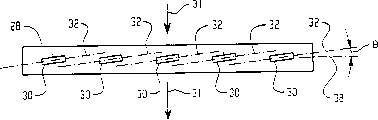
Fig. 3 and Fig. 4 represent an embodiment of rinse arm;
Fig. 5 represents the vibration output stream of fluidic oscillator nozzles;
An embodiment of Fig. 6-10 explanation fluidic oscillator nozzles;
An embodiment of Figure 11-12 explanation console (undercounter) dish washing unit;
Another embodiment of Figure 13-17 explanation fluidic oscillator nozzles.
The specific embodiment
With reference to figure 1 and Fig. 2, a conveyor-type unit 10 comprises that a conveyer belt 14 extends through housing 12 wherein.Conveyer belt 14 can be by the belt that separates, or as No. 6559607 United States Patent (USP)s in illustrated stopping type (dog-type) system form.Also can adopt the transfer system of other type, comprise pre-formation conveyer belt with the structure that is used to receive and support each vessel.Regardless of the structure of conveyer belt, the vessel reception area in the region representation housing 12 of general conveyer belt top.
Unit 10 comprises an entrance side 16 and an outlet side 18.Washing section 20 in the housing comprises that one or more being used for is directed to washing arm 22 on the vessel of advancing along conveyer belt 14 with cleaning solution or other washing medium.Cleaning solution can be with a suitable pump by being positioned at washing tank 24 circulations below the washing section, to receive the cleaning solution that drips from vessel.Jar 24 generally can comprise an overcurrent outlet and an artificial or automatic eduction gear that makes whole jar of 24 emptyings.Washing arm 22 is positioned at below the conveyer belt 14 so that cleaning solution upwards is directed on the vessel in described embodiment.Washing arm 22 also can have other position, comprises on the top and the side at housing of housing.The rinsing section 26 that is positioned at washing section 20 downstreams comprises rinse arm 28.Rinse arm 28 is directed to rinsing liquid on the vessel of advancing along conveyer belt 14.In described embodiment, go up rinse arm for one rinsing liquid is directed to downwards on the vessel, a following rinse arm upwards is directed to rinsing liquid on the vessel.Rinse arm can have other position, as towards the housing side.
With reference now to an exemplary rinse arm 28 that Fig. 3 is represented,, this arm comprise a plurality of position thereon, be used to export the fluidic oscillator nozzles 30 of each rinsing liquid stream.Fluidic oscillator nozzles generally can be any nozzle that can export oscillating fluid stream, and the direction of exporting fluid stream in other words changes in the mode of vibrating, as being described in more detail below.Under the situation of liquid, liquid stream is made up of the drop of a succession of liquid of exporting.The output stream of each nozzle strafe caused fan-shaped 32 in Fig. 4, see the most clearly, output stream 34 is that output stream constantly in Fig. 5 reflection.Arrow A 1-A5 reflects that this mouthful output stream difference drips (P1-P5) instantaneous direction in the variant moment in other words, A1 represents to export constantly the earliest the instantaneous direction that the point that flows drips P1 in other words, and A2 represents that the point of more late moment output drips the instantaneous direction of P2 in other words ... and the like.Described arm 28 comprises 5 nozzles 30, and the number of nozzle can great changes have taken place.Rinse arm 28 comprises 6 nozzles 30 down in an example, and last rinse arm comprises 5 nozzles.Described rinse arm has the axis that is approximately perpendicular to the extension of conveyer belt direction, but it should be understood that this orientation can change.
In described embodiment, rinse arm 28 is along the horizontal expansion of vessel conveyer belt 14 direction of transfers (arrow 31 of Fig. 3 and put in Fig. 4 or stretch out paper), and fluidic oscillator nozzles 30 is oriented to make rinsing liquid to cover the whole horizontal area of conveyer belt.Particularly, be under the situation of rinse arm down in rinse arm, the fan-shaped horizontal covering of stream overlaps position and the height 36 below the lucky conveyer belt 14.In addition, in described embodiment, each nozzle in a plurality of fluidic oscillator nozzles 30 all is oriented to and can prevents that its output oscillatory flow is subjected to the influence of adjacent fluid oscillator nozzles output oscillatory flow.This result makes its liquid jet vibrate with an angle θ with respect to rinse arm 28 longitudinal axis 38 by directed each nozzle 30 to realize in an example.In other words, strafing of nozzle is oblique, interacts preventing, still can guarantee to cover fully simultaneously the transverse width of conveyer belt.In an example, angle θ is in 2 °-10 ° scope, but available different angle comprises 0 °-90 ° angle.In addition, to flow interactional structure also be possible to adjacent fluid.
The water of fan nozzle output diffusion pattern, wherein many dripping exported along a plurality of directions in the diffusion pattern simultaneously, rather than exports the stream that drips with change instantaneous direction more, and fluid oscillator nozzle is a latter event.The advantage of fluidic oscillator nozzles is that the size that its output is dripped for given flow velocity is than big (under the situation of liquid) of the fan nozzle commonly used that identical flow velocity is arranged.Thereby better washing or rinsing are provided, also reduced and loose to airborne heat loss.In an example, the average droplet size of the rinsing liquid of fluidic oscillator nozzles output is than the average droplet size big at least 25% of the general fan nozzle output that identical flow velocity is arranged.Can expect, these nozzles are generally supplied with by the fluid of quite stable pressure, but nozzle can produce pulse output, as being supplied with by a liquid manifold, this liquid manifold has the associated mechanisms of a variable pressure, so that change pressure in the liquid manifold in a kind of mode of pulse.
Fig. 6-10 expresses an embodiment of the fluidic oscillator nozzles 30 of rinse arm 28.Nozzle 30 comprises one first nozzle side part 50A and one second nozzle side part 50B, the second nozzle side part 50B is configured to separate with the first nozzle side part 50A and partly be connected into a functional complete fluidic oscillator nozzles 30 with first nozzle side, and wherein the first nozzle side part 50A and the second nozzle side part 50B are identical on shape and structure.Each nozzle segment can be the molded plastic construction of an integral body, and wherein polyvinylidene fluoride (PVDF) homopolymers is represented a kind of acceptable material.Should be realized that, also available other plastics, nozzle can be made by other material in other words, for example comprises metal material or pottery.In addition, can be molded, also available other manufacturing technology is made the nozzle side part, comprises for example machining, and etching is shaped and EDM.
The two all comprises at least one outside finger (flexible fingers 70A for example that cooperates the first nozzle side part 50 and the second nozzle side part 52,70B and rigid fingers 72A are 72B) with at least one outside mating holes (for example, fixing hole 74A, 74B and movable hole 76A, 76B).The first nozzle side part 50 is arranged to also adjacent to orientation for mirror with the second nozzle side part 52 in final structure, make the outside of the nozzle side part of winning cooperate the outside mating holes of finger and second nozzle side part to mesh, the outside of second nozzle side part cooperates the outside mating holes engagement of the finger and the first nozzle side parts.
Nozzle also can comprise at least two flexible fingers 80A and 80B so that the nozzle button is inserted in the hole 29 of the suitable dimension that fits into rinse arm and suitable shape, these finger comprise skewed surface 82A separately, 82B, to insert engaging hole in the process at button, thereby finger is curved button (for example insert state, inwardly curved towards nozzle body), and finger turns back to gripping state (Figure 10) after button is inserted.The projection of nozzle 30 comprises a notch 85 that is used for receiving tool (as screwdriver), so that with as the method that prizes nozzle being taken out from the hole.In an example, in order to reduce the possibility that nozzle breaks, the protrusion of the projection of nozzle can be not more than 0.4 inch, is possible but change this distance.In another different embodiment, for the ease of with the engagement in hole 29, nozzle can comprise external screw-thread.Under the situation of metallic nozzle, nozzle can be welded on the rinse arm or on the manifold.Also can consider to use securing member.
Though two same side of the main consideration of the nozzle of front explanation are partly detained the nozzle that inserting lumps together, and should be realized that also available other connection technique.For example, use bonding agent, one or more securing members, welding, as be used for the ultrasonic bond of plastics or a kind of connection technique of brazing (being used for metal).In addition, consider that first and second nozzle side partly are structures separately though the explanation of the nozzle of front is main, but also can be configured in together, (for example, in clam shell design, between two parts of the single molded plastic parts that comprise two side parts, can be provided with a connecting hinge, two side portions can be overlapped each other and by as above-mentioned appropriate technology be linked together, to form the inner chamber of nozzle).In addition, the also nozzle arrangements of monomer available.For example, the monomer nozzle of available model casting.
With reference to Figure 10, Figure 10 illustrates the inner chamber of said nozzle again.Nozzle comprises opening 86 (for example each side partly is formed with an opening, and two openings will form inner chamber when two side portions is coupled) at two opposite sides.Particularly, these openings form an aperture 90.The size of aperture 90 and be sent to the flow velocity that the fluid pressure here jointly controls nozzle 30.The fluid stream that flows out aperture 90 points to a throat 92, and throat 92 is towards body 94 openings, and body 94 has a relevant outlet 96, and fluid flow is crossed outlet 96 from nozzle 30 outputs.The feedback control loop 98 adjacent with aperture 90 provides the pressure differential of change, to change the direction with mode of oscillation output fluid stream.Particularly, the stream output of the fluid of aperture 90 is tending towards being attached on the sidewall of throat 92, and as the result of " wall attachment effect " export fluid stream along this wall by body 94.When fluid stream is attached on the sidewall, owing near the flow at high speed this sidewall of feedback control loop 98 is tending towards producing the low-pressure state in the same side of feedback control loop 98.Therefore, fluid is attracted to low pressure zone around feedback control loop, and will press to the opposite side of throat 92 from the fluid stream of aperture 90 outputs.These conditions occur repeatedly and are attached to back and forth repeatedly on two opposite sides from the fluid stream of aperture 90 output, therefore as in Fig. 5, see the most clearly, when fluid during from mouth 96 outputs its direction vibrate.Output stream with respect to the angular orientation of nozzle-axis 201 in other words instantaneous direction change in time.Particularly, in described embodiment, output stream vibrates back and forth with respect to the plane of advancing and go out the extension of Figure 10 paper, and described nozzle-axis 201 is arranged in this plane.Two extreme positions of vibration are illustrated in 202 and 204.For purposes of illustration, described nozzle-axis 201 is determined by the straight line of the central point in central point by jet hole 96 and hole 90.But, we can say that instantaneous direction is with respect to all being changed by any nozzle-axis of determining by any two points that separate of nozzle in other words for the angular orientation of output stream, wherein the relative position between two separated points does not change.
By revising the number of degrees that its shape of nozzle can change vibration.Frequency of oscillation also is subjected to the influence of fluid pressure and medium (for example gas or liquid).In addition, also can do great change to the shape and the orientation that are arranged on the feedback control loop in the nozzle.
Should be realized that, the structure of said nozzle just can adopt many may the fluidic oscillator nozzles structures a kind of.In addition, do the output stream that either large or small two dimension moves back and forth, can consider to adopt the output fluid to do other fluid oscillating nozzle of three-dimensional vibration though typical fluidic oscillator nozzles structure provides along a plane.In addition, also should be realized that, output stream also is possible at the nozzle arrangements of " vibration " academicly not, for example, output stream moves along a direction, producing the output of a spiral or tubular, the spiral of an expansion or taper output or take place at random/irregular output with respect to the orientation of nozzle-axis.Here used term " flows to variable nozzle " and is intended to comprise any and all such nozzle arrangements, the instantaneous direction of the fluid stream of these structure outputs is with respect to the nozzle-axis time to time change, no matter variation is regular, and is irregular, vibration or nonoscillating.
Washing arm 22 can comprise that also some fluidic oscillator nozzles or other flow to variable-nozzle, and nozzle is positioned to and wash fluid can be directed on the vessel.General consideration is configured to the washing arm nozzle, makes the flow velocity of its generation be higher than the flow velocity that the rinse arm nozzle is produced, but can change, and comprises using identical rinsing and Washing spray nozzle.
Though the previous embodiment of conveyor type ware wash machine has been considered a single washing section 20 and single rinsing section 26, should be realized that, can provide the conveyer belt or the machine of a plurality of washing sections and/or a plurality of rinsing sections.Also can consider in machine, to be provided with other section, as use one or more upstream pre-wash section that flow to variable-nozzle, to export pre-washing lotion, thereby remove more food from vessel, or with one or more downstream sterile zones that flow to variable-nozzle with the output thimerosal, the air that is used to dewater with output with one or more downstream dewatering periods that flow to variable-nozzle (heating or do not heat) or other gas, perhaps downstream bringing-up section, the heating vessel at the one or more air that flow to variable-nozzle output heating of this section or steam so that for sterilization.
And, also can consider in console (undercounter) and other cabinet type unit, to use fluidic oscillator nozzles.For example, with reference to Figure 11 and 12, express an exemplary console unit among the figure, this unit comprises a definite washing/rinsing chamber 100 of cabinet shell that is formed by corrosion resistant plate and parts usually, and comprise a upper wall 110, sidewall 120 and rear wall 140 and a front door 150, the front door is hinged in the lower end shown in 160.Chamber 100 is emptied to environmental pressure by near the tortuous seal (not shown) the upper wall.Cell is supported on some leg pieces 170, these leg pieces for provide below the machine gap with allow cleaning machine below, may be that various local health regulations are desired below the cleaning machine.Bottom in the chamber is a smaller storage tank 220 as the part of the inclined floor 200 of chamber shell, and it can have a removable filter lid 230.
Above diapire, the standard Vessels rack 250 of the vessel that will wash and sterilize is equipped with in track 240 supportings, and vessel load and unload by the front door.Frame 250 can be that a rolling frame of wanting to be used for to keep together with the unit also can be a movable frame that unloads fully when planning to take out vessel.A coaxial joint 270 centrally is bearing on the lower wall 200 with this chamber.This joint provides supporting for following washing arm 300 with following rinse arm 320 again, and as routine, each arm all is rotating.Last washing arm 340 and last rinsing sprinkler head 360 support from the roof of chamber.Washing arm 300 and 340 can comprise that some suitable fluidic oscillator nozzles 302 (or other flows to variable-nozzle) are engaged in here (for example, mode or any other suitable method that has illustrated with Fig. 9).Equally, rinse arm 320 can comprise suitable fluidic oscillator nozzles 322 (or other suitable variable-nozzle that flows to), and sprinkler head 360 can comprise some suitable oscillator nozzles (or other suitable variable-nozzle that flows to).
The hot washings supply pipe 400 of cleaning stretches out and is connected on rinse arm 320 and the rinsing sprinkler head 360 from the thermal water source.Washings supply pipe 420 is connected on upper and lower washing arm 340 and 300 and the pump 450 on being installed in the outside side of chamber shell and receives washings.Pump is supplied water by an outlet 470 again, and outlet 470 stretches out from storage tank 220, and makes the washings that are sprayed on the vessel in the frame in the washing stage in machine run cycle return circulation in other words.In service cycle, pump 450 is as a circulating pump like this.
Be connected with electromagnetism injection valve 550 in the embodiment shown, give the clean water of supercharging heater bucket 580 supplies with control, the latter is a kind of displacement-type heater bucket, and its inlet is connected into and can receives water by injection valve 550, and its outlet and clean water supply pipe 400 link.The wirking pressure relief valve 590 that draws hot water when the supercharging heater has a heating element heater 700 and has the pressure in bucket to surpass predetermined value by an excess flow valve branch.Though described supercharging heater bucket 580 and pump 450 are expressed as with main dishwasher shell and are arranged side by side, but should be realized that, pump 450 and booster are arranged on host machine casing the inside, as are arranged on below the washing chamber, and embodiment is still within the limit of consideration of illustrated here various inventions.
In addition, low capacity (for example, heater 720 500W) can be arranged in storage tank 220 or the position thereon.This heater can be, for example, is embedded in a wire or a similar heating tape in the elastic material disc, and elastic material disc can be attached to the outside of storage tank, so that if desired, come water in the heating machine by energising.Heater 720 also can be arranged on inside.
One or more output gaseous fluids also can be installed in Figure 11 and 12 console unit, as air (heating or do not heat) or steam, flow to variable-nozzle, and should be realized that, modification or other cabinet type unit of many consoles unit can be arranged.
With reference now to Figure 13-17,, these figure express another the different embodiment and the installation in rinsing or washing arm thereof of fluidic oscillator nozzles.Figure 13 and 14 represents to be orientated two identical half nozzles 800 on paper, and their mounting means can be combined together them and forms a functional nozzle.The inside of per half nozzle 800 (for example all comprises some projectioies, arcuation projection 802,804 and 806 and column piece 808 and 810), these projectioies with the mode of friction fit and corresponding recesses on other half nozzle (for example, arc groove 812,814 and 816 and cylindric opening 818 and 820) match, with the form of assembly two half nozzles are kept together helping.In order more for good and all two half nozzles to be linked together, can adopt ultra-sonic welded technology, flux welding procedure or welding procedure of hot pressing.Also available screw or other securing member are added on welding and/or the friction fit or substitute them, and per half nozzle 800 also comprises a cover hub 822, and cover hub 822 is used for nozzle is connected in washing or rinse arm, as below will being described in more detail.It is worthy of note that by the combine aperture of the nozzle that produced of two and half nozzles, throat, main part, delivery outlet and feedback control loop are all mainly defined by arc protuberance 802,804 and 806.
As shown in figure 15, two half nozzles 800 are combined together to form functional nozzle 824.Facing on the position of nozzle surface 828 sealing ring 826 is being set, sealing snare 830 outwards moving with restriction sealing 826 is being provided simultaneously.The size of the protuberance 832 of nozzle 824 is made and can friction fit in the groove 834 of sealing snare 830 parts be kept together with nozzle assembly form 836 shown in Figure 16.
Shown in nozzle assembly 836 be installed among Figure 17 in exemplary washing or the rinse arm 840, wherein, the part 842 of assembly is by protruding on the arm 840, and part 844 puts in arm 840 the insides.A hole during screw 846 passes at the bottom of the arm, and be screwed into sleeve 822 by screw thread, with fixed nozzle assembly 836, wherein the screw tightness of twisting is enough to make the top of sealing ring 826 clamping arms 840, thereby forms sealing.Pressure fluid in the arm 840 flows into the ingate 848 of nozzle, and penetrates the aperture 850 in other words from outlet opening with above-mentioned mode of oscillation.Be to be noted that outlet 850 is positioned near the top of the shower nozzle that projects upwards 852 of nozzle assembly, here shower nozzle 852 be mounted convex edge 854 around.Convex edge 854 have one close on arm 840 upper surfaces below.Some can be arranged on a plurality of positions of shower nozzle 852 and provide the rigidity that increases shower nozzle when helping prevent by any other thing collision in vessel or the ware wash machine to be damaged or crooked with the rib 856 that nozzle is molded together.In molding process, when two half nozzles 800 welded together, it was smooth that these ribs can also help jet element to keep.The guard member 858 that is expressed as outstanding protrusion is arranged on the opposite side of spout 850.Spout guard member 858 is given prominence on spout 850, and spout guard member 858 is in spout 850 by the position that is bumped against earlier before bumping against like this.In order to clean under the situation that arm 840 is pulled down from ware wash machine, arm 840 may be run into, and for example the operator crashes this arm on a washing trough or other structure.Nozzle guard spare 858 can replace jet hole to accept the direct impact of any collision in these cases, thereby prevents or limited the damage/distortion of jet hole 850, and the damage/distortion of nozzle 850 has detrimental effect to the jet graphics of nozzle.
Should be well understood to, top explanation is not intended to only as an illustration and example as restriction.For example, though mainly combining with manifold fixing or rotation washing arm and/or rinse arm form, nozzle describes, but should be realized that, the manifold of available other type, for example a zone behind oscillating arms or the washing chamber's shell wall constitutes a manifold, and nozzle is fixed in the opening of this wall.In addition, manifold not necessarily because each nozzle all can be by supplying with fluid (liquid or gas) with the irrelevant road of don't bother about one by one of manifold.Though consider and (for example carry any fluid, any rinsing liquid, cleaning solution or dehydrated air) through commonly used be a plurality of nozzles, but machine may be carried a kind of given fluid or in the different phase of dish washing operation, carry different fluids with a nozzle or several identical nozzle with a single nozzle.In addition, though above-mentioned main embodiment and example have all been considered the nozzle fixing with respect to certain manifold, should be realized that nozzle can be with respect to its structure motion mounted thereto.In addition, term " rinsing liquid " and " cleaning solution " are broad sense.Because they each all might comprise the water of heating and the water of non-heating, the aqueous solution of any heating or non-heating (for example, water add washing agent as cleaning solution or rinse-added dose of water or/and disinfectant as rinsing liquid), or may be non-aqueous solution in some cases.In addition, can make some other change and modifications.
Claims (10)
1, a kind of ware wash machine comprises:
A shell comprises the zone of the vessel that a reception will be washed, and vessel comprise plate, glassware, pot, dish etc.
At least one flows to variable-nozzle, under being positioned in the shell and the fluid that is arranged to export instantaneous direction flow, change in time with respect to the described instantaneous direction of nozzle-axis, fluid flow to and points to described zone when rare, so that contact vessel.
2, ware wash machine as claimed in claim 1 also comprises:
At least one liquid manifold is positioned at described shell, and has a plurality of associated fluid oscillator nozzles, each fluidic oscillator nozzles all to be arranged to and can to flow to described zone output vibration liquid, so that the contact vessel.
3, machine as claimed in claim 2, wherein, described at least one liquid manifold comprises the rinse arm of at least one supply rinsing liquid.
4, machine as claimed in claim 3, wherein, described rinse arm is fixed, and horizontal expansion along vessel conveyer belt direction of transfer, conveyer belt runs through described shell and extends, described fluidic oscillator nozzles is positioned to guarantee that rinsing liquid covers the whole transverse area of conveyer belt, and each of a plurality of fluidic oscillator nozzles is oriented the interference that the oscillatory flow that can prevent its output is subjected to the oscillatory flow of adjacent fluid oscillator nozzles output.
5, machine as claimed in claim 2, wherein, described at least one liquid manifold comprises a tube-like piece that a plurality of openings are arranged in it, and each of a plurality of described fluidic oscillators all is positioned in the corresponding opening.
6, machine as claimed in claim 5, wherein, each described fluidic oscillator nozzles all is oriented can export its oscillatory flow like this, and promptly Pen Chu liquid is done oscillating movement with an angle that departs from described tube-like piece longitudinal axis.
7, machine as claimed in claim 2, wherein, each of a plurality of fluidic oscillator nozzles is all formed by first and second members that are combined together, and wherein, described first and second members are identical.
8, machine as claimed in claim 1 wherein, describedly flows to the jet hole guard member that variable-nozzle comprises at least one contiguous its delivery outlet.
9, machine as claimed in claim 1 also comprises:
At least one
(i) vessel conveyer belt runs through described shell and extends, and is used to deliver vessel by described shell;
(ii) vessel contain frame, move between the position of cleaning vessel that can be in described shell and the position of the loading and unloading vessel outside the described shell.
10, machine as claimed in claim 1, wherein, described variable-nozzle and the rinsing liquid of flowing to, cleaning solution, steam, the airborne source one of at least of surrounding air or heating links.
Applications Claiming Priority (4)
| Application Number | Priority Date | Filing Date | Title |
|---|---|---|---|
| US47838003P | 2003-06-13 | 2003-06-13 | |
| US60/478,380 | 2003-06-13 | ||
| US10/837,362 US20040250837A1 (en) | 2003-06-13 | 2004-05-01 | Ware wash machine with fluidic oscillator nozzles |
| US10/837,362 | 2004-05-01 |
Publications (1)
| Publication Number | Publication Date |
|---|---|
| CN1572226A true CN1572226A (en) | 2005-02-02 |
Family
ID=33303342
Family Applications (1)
| Application Number | Title | Priority Date | Filing Date |
|---|---|---|---|
| CNA2004100465753A Pending CN1572226A (en) | 2003-06-13 | 2004-06-11 | Ware wash machine with fluidic oscillator nozzles |
Country Status (7)
| Country | Link |
|---|---|
| US (3) | US20040250837A1 (en) |
| EP (1) | EP1486158B1 (en) |
| JP (1) | JP2005000667A (en) |
| KR (1) | KR20040107384A (en) |
| CN (1) | CN1572226A (en) |
| DE (1) | DE602004031177D1 (en) |
| MX (1) | MXPA04005598A (en) |
Cited By (5)
| Publication number | Priority date | Publication date | Assignee | Title |
|---|---|---|---|---|
| CN101969830B (en) * | 2008-03-11 | 2013-05-08 | 浦瑞玛柯Feg有限责任公司 | Dishwasher and method for cleaning wash ware |
| CN108354559A (en) * | 2018-04-18 | 2018-08-03 | 海底捞控股有限公司 | Chaffy dish pot cleaning device |
| WO2020034529A1 (en) * | 2018-08-15 | 2020-02-20 | 广东美的白色家电技术创新中心有限公司 | Oscillating jet device and household cleaning device |
| CN110833372A (en) * | 2018-08-15 | 2020-02-25 | 广东美的白色家电技术创新中心有限公司 | Spray rinsing device and household cleaning equipment |
| CN110833366A (en) * | 2018-08-15 | 2020-02-25 | 广东美的白色家电技术创新中心有限公司 | Spray rinsing device and domestic cleaning equipment |
Families Citing this family (51)
| Publication number | Priority date | Publication date | Assignee | Title |
|---|---|---|---|---|
| US20040250837A1 (en) * | 2003-06-13 | 2004-12-16 | Michael Watson | Ware wash machine with fluidic oscillator nozzles |
| SE527020C2 (en) * | 2004-04-27 | 2005-12-06 | Getinge Disinfection Ab | Disinfection equipment with pump device |
| US20070240742A1 (en) * | 2004-05-01 | 2007-10-18 | Kui-Chiu Kwok | Electrostatic precipitator wash system |
| US6976507B1 (en) * | 2005-02-08 | 2005-12-20 | Halliburton Energy Services, Inc. | Apparatus for creating pulsating fluid flow |
| US8066821B2 (en) * | 2005-02-09 | 2011-11-29 | Whirlpool Corporation | System for limiting pressure in a fine filter chamber for a dishwasher |
| US7610923B2 (en) * | 2005-02-09 | 2009-11-03 | Maytag Corporation | Pump and filter system for a drawer-type dishwasher |
| US7985300B2 (en) * | 2005-04-04 | 2011-07-26 | Lg Electronics Inc. | Dishwasher and assembly method thereof |
| US7784717B2 (en) * | 2005-09-28 | 2010-08-31 | General Electric Company | Methods and apparatus for fabricating components |
| KR101052779B1 (en) * | 2006-04-07 | 2011-07-29 | 삼성전자주식회사 | Dishwashers and dishwashing methods that can be steamed |
| US8500917B2 (en) * | 2007-02-09 | 2013-08-06 | Premark Feg L.L.C. | Warewasher and associated door construction |
| US7754026B2 (en) * | 2007-11-08 | 2010-07-13 | Whirlpool Corporation | Dishwasher with sonic cleaner |
| US7951244B2 (en) | 2008-01-11 | 2011-05-31 | Illinois Tool Works Inc. | Liquid cleaning apparatus for cleaning printed circuit boards |
| US7918942B2 (en) * | 2008-02-04 | 2011-04-05 | Electrolux Home Products, Inc. | Drain valve for a dishwasher and associated apparatus and method |
| US20100051063A1 (en) * | 2008-09-04 | 2010-03-04 | Champion Industries, Inc. | Ware Rinsing Apparatus |
| US8333207B2 (en) * | 2008-09-04 | 2012-12-18 | Jackson Msc Llc | Spray arm for directing spray in a warewashing machine |
| US7931754B2 (en) * | 2008-11-06 | 2011-04-26 | Whirlpool Corporation | Dishwasher with mist cleaning |
| US9272314B2 (en) * | 2008-12-19 | 2016-03-01 | Whirlpool Corporation | Dishwasher steam purge method |
| US8449693B2 (en) * | 2009-08-20 | 2013-05-28 | George C. Sheffield | Paint roller cleaning and drying apparatus |
| EP2512695A1 (en) * | 2009-12-17 | 2012-10-24 | Jackson MSC LLC | Warewashing system arm |
| US9492055B2 (en) | 2011-09-22 | 2016-11-15 | Whirlpool Corporation | Dishwasher with spray system |
| US9414736B2 (en) | 2011-09-22 | 2016-08-16 | Whirlpool Corporation | Dishwasher with directional spray |
| US9693672B2 (en) | 2011-09-22 | 2017-07-04 | Whirlpool Corporation | Dishwasher with sprayer |
| US9402526B2 (en) | 2011-09-22 | 2016-08-02 | Whirlpool Corporation | Dishwasher with spray system |
| JP5403125B2 (en) * | 2011-10-31 | 2014-01-29 | ダイキン工業株式会社 | Air conditioning indoor unit |
| ES2633591T3 (en) * | 2011-12-13 | 2017-09-22 | Ecolab Usa Inc. | Method of separating chemicals in a dishwasher |
| US9763554B2 (en) | 2012-02-14 | 2017-09-19 | Premark Feg L.L.G. | Warewash machine with removable rotating arm and related method |
| WO2013178686A1 (en) * | 2012-05-30 | 2013-12-05 | Arcelik Anonim Sirketi | A dishwasher comprising a detergent dispenser |
| US9440266B2 (en) * | 2012-11-30 | 2016-09-13 | Steris Inc. | Washer / disinfector having a water inlet diffuser |
| US9295368B2 (en) | 2013-03-01 | 2016-03-29 | Whirlpool Corporation | Dishwasher with hydraulically driven sprayer |
| US9532701B2 (en) | 2013-03-01 | 2017-01-03 | Whirlpool Corporation | Dishwasher with sprayer |
| ITCS20130012A1 (en) * | 2013-05-21 | 2014-11-22 | Giuseppe Neri | WASHING SYSTEM CONSISTING OF ROTATING ELEMENTS |
| US9713413B2 (en) | 2013-07-01 | 2017-07-25 | Whirlpool Corporation | Dishwasher for treating dishes |
| US9532699B2 (en) | 2013-07-15 | 2017-01-03 | Whirlpool Corporation | Dishwasher with sprayer |
| US20150107630A1 (en) * | 2013-08-22 | 2015-04-23 | Victoria Varnals | Systems and Methods for Cleaning Glassware |
| EP2932879B1 (en) * | 2014-03-19 | 2018-08-15 | IWT S.r.L. | Washing machine with a low number of nozzles |
| DE102014209765A1 (en) * | 2014-05-22 | 2015-11-26 | Meiko Maschinenbau Gmbh & Co. Kg | Cleaning device with improved drying |
| US10399093B2 (en) | 2014-10-15 | 2019-09-03 | Illinois Tool Works Inc. | Fluidic chip for spray nozzles |
| DE202014105113U1 (en) | 2014-10-27 | 2014-11-03 | Illinois Tool Works Inc. | Dishwasher system for dishwasher |
| NL2014837B1 (en) * | 2015-05-21 | 2017-01-31 | Nikinc Holding B V | Decontamination device and method for medical instruments. |
| DE102015117392A1 (en) * | 2015-10-13 | 2017-04-13 | Miele & Cie. Kg | Water-conducting household appliance |
| DE102015222771B3 (en) | 2015-11-18 | 2017-05-18 | Technische Universität Berlin | Fluidic component |
| DE102016015907B3 (en) | 2016-05-13 | 2022-06-23 | Fdx Fluid Dynamix Gmbh | Fluidic component |
| DE102016208344A1 (en) | 2016-05-13 | 2017-11-16 | Technische Universität Berlin | Fluidic component |
| CN109475262B (en) | 2016-07-22 | 2023-06-02 | 伊利诺斯工具制品有限公司 | Batch warewasher with energy retention curtain |
| US10989356B2 (en) | 2016-08-31 | 2021-04-27 | Raytheon Technologies Corporation | Self-retaining oil nozzle |
| US9939107B2 (en) | 2016-08-31 | 2018-04-10 | United Technologies Corporation | Self-retaining oil nozzle |
| DE102019120809A1 (en) * | 2019-08-01 | 2021-02-04 | Voith Patent Gmbh | jet |
| CN110496342B (en) * | 2019-08-29 | 2021-02-26 | 唐嘉兴 | Fire extinguisher case capable of being opened quickly based on lever principle |
| CN113926770B (en) * | 2021-09-24 | 2022-08-09 | 泰山石膏(涡阳)有限公司 | Automatic distributor for gypsum board processing and working method thereof |
| US20230101450A1 (en) * | 2021-09-30 | 2023-03-30 | Midea Group Co., Ltd. | High speed reusable beverage container washing system with pop-up sprayer |
| US20230180990A1 (en) * | 2021-12-13 | 2023-06-15 | Champion Industries, Inc. | Soaker sinks and fluid distribution assemblies |
Family Cites Families (47)
| Publication number | Priority date | Publication date | Assignee | Title |
|---|---|---|---|---|
| DE1503901A1 (en) * | 1965-07-06 | 1969-07-10 | Oberlind Veb Elektroinstall | Device for generating a pulsating liquid jet for cleaning devices |
| US3568935A (en) * | 1969-02-17 | 1971-03-09 | Gen Electric | Hinged spray plate and box for dishwashers |
| DE1920575B2 (en) * | 1969-04-23 | 1971-08-19 | Stierten-Werke AG, 7550 Rastatt | Dishwasher jet |
| US3695283A (en) * | 1970-12-02 | 1972-10-03 | Gen Electric | Fluidic oscillator |
| US3774626A (en) * | 1971-08-30 | 1973-11-27 | Tappan Co | Dishwasher water tower |
| US4325235A (en) * | 1973-05-02 | 1982-04-20 | Bowles Fluidics Corporation | Washing apparatus |
| JPS5654921Y2 (en) * | 1973-07-05 | 1981-12-22 | ||
| DE2560546C2 (en) * | 1974-09-30 | 1988-02-04 | Bowles Fluidics Corp., Silver Spring, Md., Us | |
| DE2505695A1 (en) * | 1974-09-30 | 1976-04-22 | Bowles Fluidics Corp | DEVICE FOR SPRAYING A FLUID, IN PARTICULAR FLUIDIC OSCILLATOR |
| US4157161A (en) * | 1975-09-30 | 1979-06-05 | Bowles Fluidics Corporation | Windshield washer |
| US4107990A (en) * | 1976-11-02 | 1978-08-22 | General Electric Company | Fluidic flow and velocity sensor |
| US4175575A (en) * | 1978-03-27 | 1979-11-27 | General Electric Company | Dishwasher with oscillating rotary spray arm |
| US4463904A (en) * | 1978-11-08 | 1984-08-07 | Bowles Fluidics Corporation | Cold weather fluidic fan spray devices and method |
| US4257559A (en) * | 1979-07-31 | 1981-03-24 | Noren Tore H | Removable and self sealing spray manifold for commercial dishwasher |
| US4596364A (en) * | 1984-01-11 | 1986-06-24 | Peter Bauer | High-flow oscillator |
| US4561904A (en) * | 1984-09-21 | 1985-12-31 | Hobart Corporation | Control system and method of controlling a dishwashing machine |
| US4738401A (en) * | 1987-02-24 | 1988-04-19 | Spraying Systems Co. | Quick disconnect nozzle assembly with twist-on spray tip |
| US5050249A (en) * | 1987-05-28 | 1991-09-24 | Aisin Seiki Kabushiki Kaisha | Human private parts washing apparatus |
| US5028007A (en) * | 1989-08-31 | 1991-07-02 | Lavalley Industries, Inc. | Shower pipe assembly |
| US5028077A (en) * | 1989-11-22 | 1991-07-02 | Hurst Hollis D | Adaptor for connecting a hose to a faucet |
| DE4230054A1 (en) * | 1991-06-28 | 1994-03-10 | Man Nutzfahrzeuge Ag | Multihole atomizer nozzle for fuel - is also used for liquids other than fuel |
| US5218988A (en) * | 1991-09-25 | 1993-06-15 | Beta Technology, Inc. | Liquid feed system |
| FR2684901B1 (en) * | 1991-12-13 | 1994-02-25 | Conceptair Anstalt | PROCESS AND DEVICE AVOIDING THE FORMATION OF GAS BAGS IN A TANK FOR A FLUID PRODUCT TO BE SPRAYED OR DISTRIBUTED WITHOUT AIR INTAKE |
| US5197673A (en) * | 1992-01-06 | 1993-03-30 | Vitronics Corporation | Reciprocating nozzle assembly |
| US5387313A (en) * | 1992-11-09 | 1995-02-07 | Bmc Industries, Inc. | Etchant control system |
| CZ171294A3 (en) * | 1992-11-16 | 1994-12-15 | Winterhalter Gastronom Gmbh | Dishwasher |
| JP3436785B2 (en) * | 1994-01-25 | 2003-08-18 | 芝浦メカトロニクス株式会社 | Substrate cleaning equipment |
| IT1267638B1 (en) * | 1994-12-02 | 1997-02-07 | Elbi Int Spa | DISHWASHER MACHINE. |
| US6085740A (en) * | 1996-02-21 | 2000-07-11 | Aerogen, Inc. | Liquid dispensing apparatus and methods |
| JP3323385B2 (en) * | 1995-12-21 | 2002-09-09 | 大日本スクリーン製造株式会社 | Substrate cleaning apparatus and substrate cleaning method |
| US6325081B1 (en) * | 1996-07-03 | 2001-12-04 | Kabushiki Kaisha Ultraclean Technology Research Institute | Washing apparatus and washing method |
| JP3122044B2 (en) * | 1996-08-08 | 2001-01-09 | 株式会社フジマック | Corner-mounted dishwasher |
| US5967418A (en) * | 1997-06-13 | 1999-10-19 | Macdonald; Robert W. | Spray bar for use with webs of different widths |
| US6110292A (en) * | 1997-08-12 | 2000-08-29 | Warren R. Jewett | Oscillating liquid jet washing system |
| US6021776A (en) * | 1997-09-09 | 2000-02-08 | Intertex Research, Inc. | Disposable atomizer device with trigger valve system |
| US5906317A (en) * | 1997-11-25 | 1999-05-25 | Bowles Fluidics Corporation | Method and apparatus for improving improved fluidic oscillator and method for windshield washers |
| US6026831A (en) * | 1998-11-19 | 2000-02-22 | Insinger Machine Company | Single-unit, conveyor-type washer |
| US6315221B1 (en) * | 1999-12-22 | 2001-11-13 | Visteon Global Tech., Inc. | Nozzle |
| US6964535B2 (en) * | 2000-03-24 | 2005-11-15 | The Clorox Company | Advanced cleaning system with off-head mounted nozzle |
| US6550607B1 (en) * | 2000-11-02 | 2003-04-22 | Premark Feg L.L.C. | Jam detection system for a warewasher |
| US6915901B2 (en) * | 2000-12-11 | 2005-07-12 | Marc Feinberg | Packaging assembly for surgical use |
| KR100554720B1 (en) * | 2001-01-05 | 2006-02-24 | 도토기키 가부시키가이샤 | Water discharging device |
| US6739526B2 (en) * | 2001-03-15 | 2004-05-25 | Thomas Engineering, Inc. | Spray bar assembly |
| US6988677B2 (en) * | 2002-09-11 | 2006-01-24 | Briggs & Stratton Power Products Group, Llc | Wand mounted nozzle holder |
| CN100515580C (en) * | 2003-03-27 | 2009-07-22 | 喷洒系统公司 | Modular automatic spray gun manifold |
| US6736340B1 (en) * | 2003-05-28 | 2004-05-18 | Wang Tzu-Meng | Controlling device for a sprinkler |
| US20040250837A1 (en) * | 2003-06-13 | 2004-12-16 | Michael Watson | Ware wash machine with fluidic oscillator nozzles |
-
2004
- 2004-05-01 US US10/837,362 patent/US20040250837A1/en not_active Abandoned
- 2004-06-04 DE DE602004031177T patent/DE602004031177D1/en active Active
- 2004-06-04 EP EP04013249A patent/EP1486158B1/en not_active Expired - Fee Related
- 2004-06-09 MX MXPA04005598A patent/MXPA04005598A/en active IP Right Grant
- 2004-06-10 KR KR1020040042623A patent/KR20040107384A/en not_active Application Discontinuation
- 2004-06-11 JP JP2004174257A patent/JP2005000667A/en active Pending
- 2004-06-11 CN CNA2004100465753A patent/CN1572226A/en active Pending
- 2004-12-07 US US11/005,985 patent/US7314188B2/en active Active
-
2007
- 2007-12-28 US US11/966,120 patent/US20090025758A1/en not_active Abandoned
Cited By (9)
| Publication number | Priority date | Publication date | Assignee | Title |
|---|---|---|---|---|
| CN101969830B (en) * | 2008-03-11 | 2013-05-08 | 浦瑞玛柯Feg有限责任公司 | Dishwasher and method for cleaning wash ware |
| CN108354559A (en) * | 2018-04-18 | 2018-08-03 | 海底捞控股有限公司 | Chaffy dish pot cleaning device |
| WO2020034529A1 (en) * | 2018-08-15 | 2020-02-20 | 广东美的白色家电技术创新中心有限公司 | Oscillating jet device and household cleaning device |
| CN110833372A (en) * | 2018-08-15 | 2020-02-25 | 广东美的白色家电技术创新中心有限公司 | Spray rinsing device and household cleaning equipment |
| CN110833373A (en) * | 2018-08-15 | 2020-02-25 | 广东美的白色家电技术创新中心有限公司 | Oscillating jet device and household cleaning equipment |
| CN110833366A (en) * | 2018-08-15 | 2020-02-25 | 广东美的白色家电技术创新中心有限公司 | Spray rinsing device and domestic cleaning equipment |
| CN110833372B (en) * | 2018-08-15 | 2021-07-27 | 广东美的白色家电技术创新中心有限公司 | Spray rinsing device and household cleaning equipment |
| CN110833373B (en) * | 2018-08-15 | 2021-12-17 | 广东美的白色家电技术创新中心有限公司 | Oscillating jet device and household cleaning equipment |
| CN110833366B (en) * | 2018-08-15 | 2023-09-01 | 广东美的白色家电技术创新中心有限公司 | Spray washing device and household cleaning equipment |
Also Published As
| Publication number | Publication date |
|---|---|
| US20040250837A1 (en) | 2004-12-16 |
| KR20040107384A (en) | 2004-12-20 |
| EP1486158B1 (en) | 2011-01-26 |
| EP1486158A1 (en) | 2004-12-15 |
| US20090025758A1 (en) | 2009-01-29 |
| JP2005000667A (en) | 2005-01-06 |
| DE602004031177D1 (en) | 2011-03-10 |
| US20050077399A1 (en) | 2005-04-14 |
| US7314188B2 (en) | 2008-01-01 |
| MXPA04005598A (en) | 2005-06-03 |
Similar Documents
| Publication | Publication Date | Title |
|---|---|---|
| CN1572226A (en) | Ware wash machine with fluidic oscillator nozzles | |
| US7673639B2 (en) | Washing arm and dishwasher having the same | |
| EP1847207B1 (en) | Wash/rinse system for a drawer-type dishwasher | |
| EP0943281B1 (en) | Feed system for a middle-level spray arm | |
| US7931754B2 (en) | Dishwasher with mist cleaning | |
| WO2001058335A1 (en) | Washing machine | |
| RU2660030C2 (en) | Dishwasher containing at least one dishwasher spraying device | |
| CN108697298B (en) | Dish washing machine | |
| US11464391B2 (en) | Spray arm assembly | |
| CN101347317B (en) | Dish washer | |
| EP0772994B1 (en) | Dishwashing machine with improved hydraulic circuit | |
| JP2021011150A (en) | Cleaning device | |
| KR101634173B1 (en) | Dish washer | |
| JP3835348B2 (en) | dishwasher | |
| EP3546834A1 (en) | Oven provided with a washing system | |
| JP3829777B2 (en) | dishwasher | |
| EP3260032B1 (en) | Warewasher with air assisted prescrapping | |
| US20180338669A1 (en) | Warewasher with intermediate blowoff zone or cycle step | |
| JP3835347B2 (en) | dishwasher | |
| JP2010268983A (en) | Dishwasher | |
| JPH05115420A (en) | Small thing containing device for tableware washing machine | |
| JP2020001024A (en) | Washer | |
| JP2020001025A (en) | Washer | |
| KR940007658Y1 (en) | Tableware washing machine | |
| JP2002000537A (en) | Washing system and nozzle for tableware or the like |
Legal Events
| Date | Code | Title | Description |
|---|---|---|---|
| C06 | Publication | ||
| PB01 | Publication | ||
| C10 | Entry into substantive examination | ||
| SE01 | Entry into force of request for substantive examination | ||
| AD01 | Patent right deemed abandoned |
Effective date of abandoning: 20050202 |
|
| C20 | Patent right or utility model deemed to be abandoned or is abandoned |