EP1486158B1 - Ware wash machine with fluidic oscillator nozzles - Google Patents
Ware wash machine with fluidic oscillator nozzles Download PDFInfo
- Publication number
- EP1486158B1 EP1486158B1 EP04013249A EP04013249A EP1486158B1 EP 1486158 B1 EP1486158 B1 EP 1486158B1 EP 04013249 A EP04013249 A EP 04013249A EP 04013249 A EP04013249 A EP 04013249A EP 1486158 B1 EP1486158 B1 EP 1486158B1
- Authority
- EP
- European Patent Office
- Prior art keywords
- nozzle
- fluidic oscillator
- nozzles
- rinse
- housing
- Prior art date
- Legal status (The legal status is an assumption and is not a legal conclusion. Google has not performed a legal analysis and makes no representation as to the accuracy of the status listed.)
- Expired - Fee Related
Links
- 239000007788 liquid Substances 0.000 claims description 41
- 238000004140 cleaning Methods 0.000 claims description 4
- 239000011521 glass Substances 0.000 claims description 2
- 230000002452 interceptive effect Effects 0.000 claims description 2
- -1 steam Substances 0.000 claims description 2
- 239000003570 air Substances 0.000 claims 1
- 239000012080 ambient air Substances 0.000 claims 1
- 239000012530 fluid Substances 0.000 description 21
- XLYOFNOQVPJJNP-UHFFFAOYSA-N water Substances O XLYOFNOQVPJJNP-UHFFFAOYSA-N 0.000 description 15
- 238000010276 construction Methods 0.000 description 13
- 238000000034 method Methods 0.000 description 7
- 238000001035 drying Methods 0.000 description 6
- 230000013011 mating Effects 0.000 description 6
- 238000005406 washing Methods 0.000 description 6
- 238000003466 welding Methods 0.000 description 6
- 238000011012 sanitization Methods 0.000 description 5
- 238000010438 heat treatment Methods 0.000 description 4
- 238000003780 insertion Methods 0.000 description 4
- 230000037431 insertion Effects 0.000 description 4
- 230000008569 process Effects 0.000 description 4
- 239000007921 spray Substances 0.000 description 4
- 239000003795 chemical substances by application Substances 0.000 description 3
- 239000000463 material Substances 0.000 description 3
- 230000010355 oscillation Effects 0.000 description 3
- 239000002033 PVDF binder Substances 0.000 description 2
- 239000003599 detergent Substances 0.000 description 2
- 238000009434 installation Methods 0.000 description 2
- 230000007246 mechanism Effects 0.000 description 2
- 239000002184 metal Substances 0.000 description 2
- 229910052751 metal Inorganic materials 0.000 description 2
- 239000002991 molded plastic Substances 0.000 description 2
- 239000004033 plastic Substances 0.000 description 2
- 229920003023 plastic Polymers 0.000 description 2
- 229920002981 polyvinylidene fluoride Polymers 0.000 description 2
- 230000003134 recirculating effect Effects 0.000 description 2
- 239000000853 adhesive Substances 0.000 description 1
- 230000001070 adhesive effect Effects 0.000 description 1
- 230000002411 adverse Effects 0.000 description 1
- 238000005452 bending Methods 0.000 description 1
- 230000008901 benefit Effects 0.000 description 1
- 238000005219 brazing Methods 0.000 description 1
- 239000000919 ceramic Substances 0.000 description 1
- 230000008859 change Effects 0.000 description 1
- 238000006073 displacement reaction Methods 0.000 description 1
- 230000000694 effects Effects 0.000 description 1
- 238000009760 electrical discharge machining Methods 0.000 description 1
- 238000005530 etching Methods 0.000 description 1
- 235000013410 fast food Nutrition 0.000 description 1
- 235000013305 food Nutrition 0.000 description 1
- 239000013505 freshwater Substances 0.000 description 1
- 229920001519 homopolymer Polymers 0.000 description 1
- 238000003754 machining Methods 0.000 description 1
- 239000007769 metal material Substances 0.000 description 1
- 150000002739 metals Chemical class 0.000 description 1
- 238000012986 modification Methods 0.000 description 1
- 230000004048 modification Effects 0.000 description 1
- 238000000465 moulding Methods 0.000 description 1
- 238000009740 moulding (composite fabrication) Methods 0.000 description 1
- 230000003534 oscillatory effect Effects 0.000 description 1
- 238000009428 plumbing Methods 0.000 description 1
- 238000005096 rolling process Methods 0.000 description 1
- 238000007789 sealing Methods 0.000 description 1
- 239000002904 solvent Substances 0.000 description 1
- 229910001220 stainless steel Inorganic materials 0.000 description 1
- 239000010935 stainless steel Substances 0.000 description 1
- 238000011144 upstream manufacturing Methods 0.000 description 1
Images


Classifications
-
- A—HUMAN NECESSITIES
- A47—FURNITURE; DOMESTIC ARTICLES OR APPLIANCES; COFFEE MILLS; SPICE MILLS; SUCTION CLEANERS IN GENERAL
- A47L—DOMESTIC WASHING OR CLEANING; SUCTION CLEANERS IN GENERAL
- A47L15/00—Washing or rinsing machines for crockery or tableware
- A47L15/14—Washing or rinsing machines for crockery or tableware with stationary crockery baskets and spraying devices within the cleaning chamber
- A47L15/18—Washing or rinsing machines for crockery or tableware with stationary crockery baskets and spraying devices within the cleaning chamber with movably-mounted spraying devices
-
- B—PERFORMING OPERATIONS; TRANSPORTING
- B05—SPRAYING OR ATOMISING IN GENERAL; APPLYING FLUENT MATERIALS TO SURFACES, IN GENERAL
- B05B—SPRAYING APPARATUS; ATOMISING APPARATUS; NOZZLES
- B05B1/00—Nozzles, spray heads or other outlets, with or without auxiliary devices such as valves, heating means
- B05B1/02—Nozzles, spray heads or other outlets, with or without auxiliary devices such as valves, heating means designed to produce a jet, spray, or other discharge of particular shape or nature, e.g. in single drops, or having an outlet of particular shape
- B05B1/08—Nozzles, spray heads or other outlets, with or without auxiliary devices such as valves, heating means designed to produce a jet, spray, or other discharge of particular shape or nature, e.g. in single drops, or having an outlet of particular shape of pulsating nature, e.g. delivering liquid in successive separate quantities ; Fluidic oscillators
-
- A—HUMAN NECESSITIES
- A47—FURNITURE; DOMESTIC ARTICLES OR APPLIANCES; COFFEE MILLS; SPICE MILLS; SUCTION CLEANERS IN GENERAL
- A47L—DOMESTIC WASHING OR CLEANING; SUCTION CLEANERS IN GENERAL
- A47L15/00—Washing or rinsing machines for crockery or tableware
- A47L15/14—Washing or rinsing machines for crockery or tableware with stationary crockery baskets and spraying devices within the cleaning chamber
- A47L15/16—Washing or rinsing machines for crockery or tableware with stationary crockery baskets and spraying devices within the cleaning chamber with rigidly-mounted spraying devices
-
- A—HUMAN NECESSITIES
- A47—FURNITURE; DOMESTIC ARTICLES OR APPLIANCES; COFFEE MILLS; SPICE MILLS; SUCTION CLEANERS IN GENERAL
- A47L—DOMESTIC WASHING OR CLEANING; SUCTION CLEANERS IN GENERAL
- A47L15/00—Washing or rinsing machines for crockery or tableware
- A47L15/14—Washing or rinsing machines for crockery or tableware with stationary crockery baskets and spraying devices within the cleaning chamber
- A47L15/18—Washing or rinsing machines for crockery or tableware with stationary crockery baskets and spraying devices within the cleaning chamber with movably-mounted spraying devices
- A47L15/20—Swingable spraying devices
-
- A—HUMAN NECESSITIES
- A47—FURNITURE; DOMESTIC ARTICLES OR APPLIANCES; COFFEE MILLS; SPICE MILLS; SUCTION CLEANERS IN GENERAL
- A47L—DOMESTIC WASHING OR CLEANING; SUCTION CLEANERS IN GENERAL
- A47L15/00—Washing or rinsing machines for crockery or tableware
- A47L15/24—Washing or rinsing machines for crockery or tableware with movement of the crockery baskets by conveyors
- A47L15/247—Details specific to conveyor-type machines, e.g. curtains
-
- A—HUMAN NECESSITIES
- A47—FURNITURE; DOMESTIC ARTICLES OR APPLIANCES; COFFEE MILLS; SPICE MILLS; SUCTION CLEANERS IN GENERAL
- A47L—DOMESTIC WASHING OR CLEANING; SUCTION CLEANERS IN GENERAL
- A47L15/00—Washing or rinsing machines for crockery or tableware
- A47L15/42—Details
- A47L15/4214—Water supply, recirculation or discharge arrangements; Devices therefor
- A47L15/4219—Water recirculation
-
- A—HUMAN NECESSITIES
- A47—FURNITURE; DOMESTIC ARTICLES OR APPLIANCES; COFFEE MILLS; SPICE MILLS; SUCTION CLEANERS IN GENERAL
- A47L—DOMESTIC WASHING OR CLEANING; SUCTION CLEANERS IN GENERAL
- A47L15/00—Washing or rinsing machines for crockery or tableware
- A47L15/42—Details
- A47L15/4278—Nozzles
-
- B—PERFORMING OPERATIONS; TRANSPORTING
- B05—SPRAYING OR ATOMISING IN GENERAL; APPLYING FLUENT MATERIALS TO SURFACES, IN GENERAL
- B05B—SPRAYING APPARATUS; ATOMISING APPARATUS; NOZZLES
- B05B15/00—Details of spraying plant or spraying apparatus not otherwise provided for; Accessories
- B05B15/60—Arrangements for mounting, supporting or holding spraying apparatus
- B05B15/65—Mounting arrangements for fluid connection of the spraying apparatus or its outlets to flow conduits
- B05B15/658—Mounting arrangements for fluid connection of the spraying apparatus or its outlets to flow conduits the spraying apparatus or its outlet axis being perpendicular to the flow conduit
Definitions
- the present application relates generally to machines used to wash kitchen wares such as dishes, glasses, utensils and pots and pans, and more particularly to a ware wash machine that makes effective use of one or more fluidic oscillator nozzles (or other variable stream orientation nozzles as defined below) in one or more areas of the machine.
- the former may include a single chamber into which a rack of soiled ware can be placed. Within the chamber, the entire cleaning process, typically including washing, rinsing and drying is performed on the rack. Multiple racks must be washed sequentially, with each rack being completely cleaned before the next can be operated upon.
- a conveyor-type machine includes a conveyor for carrying individual items or entire racks of ware through multiple stations within the machine housing. A different operation may be carried out at each station, such as washing, rinsing, or drying.
- multiple items or racks of ware can be placed on the conveyor and moved continuously through the machine so that, for example, while one item or rack is being rinsed, a preceding item or rack can be dried.
- One difficulty encountered in the construction of such machines, regardless of type, is balancing effective washing and rinsing with the goal of limiting the amount of liquid, detergents, rinse agents and sanitizers used for such washing and rinsing.
- a ware wash machine comprising the features of the preamble of claim 1 is known from DE 19 20 575 .
- one or more fluidic oscillator nozzles or other variable stream orientation nozzles are used for outputting one or more of a rinse liquid, a wash liquid, and a drying or heating gas such as air (heated or unheated) or steam.
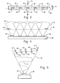
- Fig. 1 is a perspective view of one embodiment of a conveyor-type unit
- Fig. 2 is a side elevation of the unit of Fig. 1 ;
- Figs. 3 and 4 shows one embodiment of a rinse arm
- Fig. 5 depicts an oscillating output stream of a fluidic oscillator nozzle
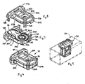
- Fig. 6-10 illustrate one embodiment of a fluidic oscillator nozzle
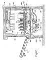
- Figs. 11-12 illustrate one embodiment of an undercounter ware wash box-type unit
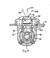
- Figs. 13-17 illustrate another embodiment of a fluidic oscillator nozzle.
- a conveyor-type unit 10 includes a housing 12 with a conveyor 14 extending therethrough.
- the conveyor 14 may be formed by spaced apart belts or a dog-type system as described in U.S. Patent No. 6,550,607 .
- Other types of conveyor systems could also be used, including conveyors pre-formed with structures for receiving and supporting individual wares.
- the region generally above the conveyor represents a ware receiving area within the housing 12.
- the unit 10 includes an entry side 16 and an exit side 18.
- a wash section 20 within the housing includes one or more wash arms 22 for directing wash liquid or other wash media onto wares traveling along the conveyor 14.
- the wash liquid may be recirculated by a suitable pump through a wash liquid tank 24 located beneath the wash section to receive the wash liquid as it falls from the wares.
- the tank 24 may typically include an overflow drain as well as a manual or automatic drain mechanism to enable draining of the entire tank 24.
- the wash arms 22 are located beneath the conveyor 14 to direct wash liquid upward onto the wares. Other locations for the wash arms 22 are possible, including toward the top of the housing and on the sides of the housing.
- a rinse section 26 located downstream of the wash section 20 includes rinse arms 28 that direct rinse liquid onto wares traveling along the conveyor 14.
- an upper rinse arm directs rinse liquid downward onto the wares and a lower rinse arm directs rinse liquid upward onto the wares.
- Other locations for the rinse arms are possible, such as toward the sides of the housing.
- the arm includes a plurality of fluidic oscillator nozzles 30 positioned thereon for outputting respective streams of rinse liquid.
- a fluidic oscillator nozzle is generally any nozzle that outputs an oscillating stream of fluid, meaning that the direction of the output stream of fluid varies in an oscillatory manner as will be described in greater detail below.
- the stream of liquid is typically made up of a series of drops of the liquid being output.
- the resulting fan-shape 32 covered by the sweep of the output stream of each nozzle is best seen in Fig. 4 , with the output stream 34 at a given moment in time reflected in Fig. 5 .
- Arrows A1-A5 reflect the instantaneous direction of different points or drops (P1-P5) of the stream output by the port at respectively different times, A1 representing instantaneous direction for point or drop P1 of the stream output at an earliest point in time, A2 representing instantaneous direction for point or drop P2 output at a later time and so on.
- the illustrated arm 28 includes five nozzles 30, but the number could vary considerably.
- the lower rinse arm 28 includes six nozzles 30 and the upper rinse arm includes five nozzles.
- the illustrated rinse arm has an axis that extends substantially perpendicular to the direction of the conveyor, but it is recognized that variations on this orientation are possible.
- the rinse arm 28 extends in a direction across a conveying direction (arrows 31 of Fig. 3 and into or out of the page in Fig. 4 ) of the ware conveyor 14 and the fluidic oscillator nozzles 30 are located to assure that rinse liquid covers an entire lateral area of the conveyor.
- the rinse arm is a lower rinse arm
- the fan-shaped lateral coverage of the streams overlaps at a location/height 36 that is just below the level of the conveyor 14.
- each of the plurality of fluidic oscillator nozzles 30 is oriented to prevent its output oscillating stream from interfering with oscillating streams output by adjacent fluidic oscillator nozzles.
- this result is achieved by orienting each nozzle 30 to output its oscillating stream such that oscillating movement of ejected liquid occurs at an angle ⁇ relative to a longitudinal axis 38 of the rinse arm 28.
- the sweep of the nozzles is skewed to prevent the interference while still assuring complete coverage across the width of the conveyor.
- the angle ⁇ may be in the range of about two to ten degrees, but variations are possible, including angles from zero to ninety degrees.
- Fanjet nozzles output water in a spread pattern, with drops simultaneously output in multiple directions within the spread, rather than outputting a stream of drops with changing instantaneous direction as fluidic oscillator nozzles do.
- Fluidic oscillator nozzles can provide an advantage of larger output drop size (in the case of liquids) for a given flow rate than commonly used fanjet nozzles having the same flow rate, providing better washing or rinsing and also reducing heat loss to the air.
- fluidic oscillators outputs rinse liquid with an average drop size at least twenty-five percent greater than that output by a typical fanjet nozzle having the same flow rate.
- the nozzles will typically be fed by a relatively constant pressure fluid, but a pulsing output from the nozzles could be produced, as by using a liquid manifold having an associated variable pressure mechanism to vary the pressure within the liquid manifold in a pulsed manner.
- the nozzle 30 includes a first nozzle side part 50A, a second nozzle side part 50B constructed separate from the first nozzle side part 50A and connected to the first nozzle side part to form a functioning, complete fluidic oscillator nozzle 30, wherein the first nozzle side part 50A and second nozzle side part 50B are identical in shape and configuration.
- Each nozzle side part may be of unitary, molded plastic construction, with a Polyvinylidene Fluoride (PVDF) homopolymer representing one acceptable material. It is also recognized that other plastics could be used, or the nozzle could be constructed of other materials including, by way of example, metallic materials or ceramics. Further, rather than being molded, other construction techniques for the nozzle side parts could be used including, by way of example, machining, etching, forming and EDM.
- PVDF Polyvinylidene Fluoride
- the nozzle side parts 50A and 50B have respective internal sides 52A and 52B and respective external sides 54A and 54B.
- the internal sides have identical protrusions (e.g., curved ridge 56, curved ridge 58 and post 60) and identical recesses (e.g., curved recess 62, curved recess 64 and post receiving aperture 66).
- the first nozzle side part 50 is arranged in mirror image orientation relative to and adjacent the second nozzle side part 52 such that the protrusions of the first nozzle side part frictionally engage into the recesses of the second nozzle side part and the protrusions of the second nozzle side part frictionally engage into the recesses of the first nozzle side part.
- Such engagement aids in holding the side parts together and also performs a sealing function for the cavity formed internal of the nozzle 30.
- Both the first nozzle side part 50 and the second nozzle side part 52 include at least one exterior mating finger (e.g., flexible fingers 70A, 70B and rigid fingers 72A, 72B) and at least one exterior mating opening (e.g., fixed openings 74A, 74B and movable openings 76A, 76B).
- the first nozzle side part 50 is arranged in mirror image orientation relative to and adjacent the second nozzle side part 52 such that the exterior mating finger(s) of the first nozzle side part engage the exterior mating opening(s) of the second nozzle side part and the exterior mating finger(s) of the second nozzle side part engages the exterior mating opening(s) of the first nozzle side part.
- the nozzle may also include at least two flexible fingers 80A and 80B to facilitate snap-fit insertion of the nozzle into an appropriately sized and shaped opening 29 of the rinse arm, such fingers including respective surfaces 82A, 82B ramped to engage an opening during insertion to flex the fingers to an insertion position (e.g., inward toward the nozzle body), and the fingers returning to a holding position ( Fig. 10 ) after insertion.
- the protruding part of the nozzle 30 includes a notch 85 to receive a tool (such as a screwdriver) to enable removal of the nozzle from the opening as by a prying operation.
- the protruding part of the nozzle may protrude no more than about 1 cm (0.4 inches) in order to reduce the potential for nozzle breakage, but variations on this distance are possible.
- the nozzle may include exterior threads to facilitated engagement with the opening in the opening 29. In the case of metal nozzles, they could be welded to the rinse arm or other manifold. The use of fasteners is also contemplated.
- connection by one of an adhesive, one or more fasteners, a welding operation, such as ultrasonic welding for plastics, or a brazing operation (for metals) might be used.
- first and second nozzle side parts constructed separately they could be constructed together (e.g., as in a clamshell-type configuration including a connecting hinge could be provided between a single molded plastic piece including the two side parts, enabling the side parts to be folded against each other and connected together, as by any suitable technique previously mentioned, to form the internal cavity of the nozzle).
- a one piece nozzle construction could also be used.
- an investment cast one-piece nozzle could be used.
- the nozzle includes openings 86 on opposite sides (e.g., each side part is formed with an opening that will lead to the internal cavity when the side parts are connected).
- the openings lead to an orifice 90.
- the size of the orifice 90 in combination with the pressure of the fluid delivered thereto controls the flow rate of the nozzle 30.
- the fluid stream exiting the orifice 90 is directed towards a throat 92 that opens to a body portion 94 having an associated exit port 96 through which the fluid stream is output from the nozzle 30.
- a feedback loop 98 located adjacent the orifice 90 provides a changing pressure differential to vary the direction of the output fluid stream in an oscillating manner.
- the fluid stream output from the orifice 90 tends to attach to one sidewall of the throat 92 and as a result of the "Coanda Effect" follows that wall through the body portion 94.
- the fluid stream attaches to one sidewall it tends to create a low pressure condition on the same side of the feedback loop 98 due to the high speed flow near that side of the feedback loop 98.
- fluid is drawn around the feedback loop toward the low pressure region and toggles the fluid stream exiting the orifice 90 toward the opposite sidewall of the throat 92.
- the angular orientation or instantaneous direction of the output stream with respect to an axis 201 of the nozzle varies over time.
- the output stream oscillates back and forth relative to a plane extending in and out of the page in Fig. 10 , where the illustrated nozzle axis 201 lies in the plane.
- the two extremes of oscillation are represented at 202 and 204.
- the illustrated nozzle axis 201 is defined by a line passing though the center point of the nozzle port 96 and the center point of the orifice 90.
- the angular orientation or instantaneous direction of the output stream can be said to vary relative to any nozzle axis defined by a line passing through any two spaced apart points on the nozzle, where the relative position between the two spaced apart points does not change.
- Varying degrees of oscillation can be achieved by modifying the nozzle configuration. Oscillating frequency is also affected by fluid pressure and medium (e.g., gas or liquid). Further, the shape and orientation of the feedback loop provided within the nozzle could vary significantly.
- fluid pressure and medium e.g., gas or liquid
- nozzle construction is one of many possible fluidic oscillator nozzle constructions that could be used.
- typical fluidic oscillator nozzle construction provides an output stream that, more or less, moves back and forth in two-dimensions along a plane, it is contemplated that other fluidic oscillator nozzle constructions could be used where the oscillation occurs in three dimensions.
- nozzle constructions in which the output stream technically does not "oscillate" are possible, such as an output stream that moves in one direction to produce a helical or cylindrical output, an expanding helical or cone-shaped output or an output stream having an orientation that varies randomly/chaotically relative to the axis of the nozzle.
- variable stream orientation nozzle is intended to encompass any and all such nozzle constructions that output a stream of fluid with an instantaneous direction that varies over time relative to a nozzle axis, regardless of whether the variance is regular, random, oscillating or non-oscillating.
- the wash arms 22 could also include fluidic oscillator nozzles or other variable stream orientation nozzles positioned therein to direct wash fluid onto the wares. It is generally contemplated that the wash arm nozzles would be constructed to produce a higher flow rate than the rinse arm nozzles, but variations are possible, including the use of identical nozzles for both rinse and wash.
- conveyor-type ware wash machine contemplates a single wash section 20 and a single rinse section 26, it is recognized that conveyor-type machines having multiple wash sections and/or multiple rinse sections could be provided. It is further contemplated that other sections could be provided within the machine, such as an upstream pre-wash section using one or more variable stream orientation nozzles to output a pre-wash liquid to remove larger food materials from wares or to output steam, a downstream sanitizing section using one or more variable stream orientation nozzles to output a sanitizing liquid, a downstream drying section using one or more variable stream orientation nozzles to output air (heated or unheated) or some other gas for drying, or a downstream heating section in which heated air or steam is output by one or more variable stream orientation nozzles to heat the wares for sanitizing purposes.
- an upstream pre-wash section using one or more variable stream orientation nozzles to output a pre-wash liquid to remove larger food materials from wares or to output steam
- a downstream sanitizing section
- an exemplary undercounter unit includes a washing/rinsing chamber 100 that is defined by a cabinet, housing usually formed of stainless steel panels and components, and including a top wall 110, side walls 120 and rear wall 140, and a front facing door 150, hinged at its lower end, as indicated at 160.
- the chamber 100 is vented to ambient pressure through labyrinth seals (not shown) near the top wall.
- the cabinet is supported upon legs 170 which provide the clearance for the underside of the machine to permit cleaning beneath it as may be required by various local sanitation codes.
- a relatively small sump 220 that may have a removable strainer cover 230.
- rails 240 provide support for standard ware racks 250, loaded with ware to be washed and sanitized, which are loaded and unloaded through the front door.
- the rack 250 may be a rolling rack intended to remain with the unit or may be a mobile rack intended to be removed entirely when the wares are removed.
- a coaxial fitting 270 is supported on the lower wall 200, centrally of the chamber, and this fitting in turn provides support for a lower wash arm 300 and lower rinse arm 320, each being rotational as is common.
- An upper wash arm 340 and upper rinse spray heads 360 are supported from the top wall of the chamber.
- the wash arms 300 and 340 may include suitable fluidic oscillator nozzles 302 (or other variable stream orientation nozzles) incorporated therein (e.g., as in the manner previously described with respect to Fig. 9 or any other suitable manner).
- rinse arm 320 may include suitable fluidic oscillator nozzles 322 (or other variable stream orientation nozzles), and the spray heads 360 may include suitable fluidic oscillator nozzles (or other variable stream orientation nozzles).
- the fresh hot rinse water supply line 400 extends from a source of hot water and is connected to the rinse arm 320 and rinse spray heads 360.
- the wash water supply line 420 is connected to the upper and lower wash arms 340 and 300, and receives wash water from a pump 450 mounted to one side of and exterior of the cabinet.
- the pump in turn is supplied from an outlet pipe 470 that extends from sump 220 and returns or recirculates the wash water sprayed over the ware in the rack during the wash segment of the machine cycle.
- pump 450 functions as a recirculating pump means.
- a solenoid operated drain valve 480 is connected by a branch or drain pipe 490 to the wash water supply line 420 immediately downstream of the outlet of pump 450, and this valve when open allows flow of the pump discharge to a drain line 500 that may be connected into a suitable kitchen drain system 520, according to the applicable code regulations. In many kitchens in newer fast food restaurants the drain system may be considerably above the floor, thus the pumped discharge from the dishwasher is a desired feature in those installations. Also, when the drain valve is open, the path of least resistance to the pump output is through drain valve 480, and flow through the recirculating wash plumbing quickly diminishes due to back pressure created at the nozzles of the wash arms. At this time the pump 450 functions as a drain pump means. During the normal cycle of operations of this machine, drain valve 480 is opened once each cycle of operation, after the wash segment and before the rinse segment of the cycle.
- a solenoid-operated fill valve 550 is connected, in the embodiment shown, to control the supply of fresh water to a booster heater tank 580, which is a displacement type heater tank having its inlet connected to receive water through fill valve 550, and its outlet connected to the fresh rinse water supply line 400.
- the booster heater has a heating element 700 and has the usual pressure relief valve 590 which will divert hot water through an overflow pipe in the event the tank pressure exceeds a predetermined value. While the illustrated booster heater tank 580 and pump 450 are shown alongside the main dishwasher housing, it is recognized that embodiments in which the pump 450 and booster are provided internal to the main housing, such as beneath the wash chamber, are within the contemplated scope of the various inventions described herein.
- a low capacity (e.g. 500 W) heater 720 may be located in or on the sump 220.
- a low capacity (e.g. 500 W) heater 720 may be located in or on the sump 220.
- a heater may be, for example, a wire or similar heating strip embodied in an elastomeric pad that can be adhered to the exterior of the sump to heat water in the machine by conduction, if necessary.
- the heater 720 may alternatively be provided internally.
- the undercounter unit of Figs. 11 and 12 could also incorporate one or more variable stream orientation nozzles that output a gaseous fluid, such as air (heated or unheated) or steam, and it is recognized that numerous variations on undercounter units or other box units are possible.
- a gaseous fluid such as air (heated or unheated) or steam
- FIGs. 13-17 an alternative embodiment of a fluidic oscillator nozzle and its installation in a rinse or wash arm is shown.
- Figs. 13 and 14 represent identical nozzle halves 800 oriented on the page in a manner that permits them to be fitted together to form a functional nozzle.
- the internal side of each nozzle half 800 includes protrusions (e.g., curved protrusions 802, 804 and 806, and posts 808 and 810) that mate with corresponding recesses (e.g., curved recesses 812, 814 and 816 and cylindrical openings 818 and 820) on the other nozzle half in a friction fit manner to aid in holding the two nozzle halves together in assembled form.
- protrusions e.g., curved protrusions 802, 804 and 806, and posts 808 and 810
- corresponding recesses e.g., curved recesses 812, 814 and 816 and cylindrical openings 818 and 820
- Each nozzle half 800 also includes a boss 822, which can be used for connecting the nozzle in a wash or rinse arm as described in further detail below.
- the orifice, throat, body portion, output port and feedback loop of the nozzle created by combined nozzle halves 800 are all primarily defined by the curved protrusions 802, 804 and 806.
- nozzle halves 800 combine to form a functional nozzle 824.
- a gasket/seal 826 may be provided for location against surface 828 of the nozzle, with gasket housing 830 provided to limit the outward movement of the gasket 826.
- Protrusions 832 of the nozzle 824 are sized for frictionally fitting in recesses 834 of the gasket housing 830 to hold the components together in the nozzle assembly form 836 shown in Fig. 16 .
- Nozzle assembly 836 is shown mounted in exemplary wash or rinse arm 840 in Fig. 17 , with portion 842 of the assembly protruding from the arm 840 and with portion 844 internal to the arm 840.
- a screw 846 is positioned through an opening in the bottom of the arm and threaded into boss 822 to secure the nozzle assembly 836, with the screw tightened sufficiently to cause the gasket 826 to form a seal against the top of the arm 840.
- Fluid under pressure within the arm 840 flows into inlet opening 848 of the nozzle and is ejected from exit port or orifice 850 in an oscillating manner as previously described.
- exit port 850 is located near the top of an upwardly projecting nozzle head 852 of the nozzle assembly, where nozzle head 852 is surrounded by a mounting flange 854 having an underside adjacent the top surface of arm 840.
- Ribs 856 which may be molded with the nozzle, are disposed at multiple locations around the nozzle head 852 and provide increased stiffness to aid in keeping the nozzle head from breaking or bending if impacted by wares or anything else within the ware wash machine. The ribs can also aid in keeping the nozzle part flat during molding and when the nozzle halves 800 are welded together.
- Nozzle port guards 858 illustrated in the form of projecting bumps, are disposed on opposite sides of the nozzle port 850.
- the port guards 858 project above the nozzle port 850 so that the port guards 858 are in position to be impacted before the nozzle port 850.
- the arm 840 could be subjected to impacts, such as an operator banging the arm against a sink or other structure.
- the nozzle guards 858 should take the brunt of any impact instead of the nozzle port 850, thereby preventing or limiting damage/deformation of the nozzle port 850, which could adversely affect the spray pattern of the nozzle.
- nozzles are primarily described in association with manifolds in the form of stationary or rotating wash arms and/or rinse arms, it is recognized that other manifold types could be used, such as an oscillating arm or the wall of a wash chamber housing where the area behind the wall constitutes a manifold and nozzles are fixed in openings of the wall. Further, a manifold is not required, as each nozzle could be supplied with its fluid (liquid or gas) by an individual line not associated with any manifold.
- any one fluid e.g., any one of a rinse liquid, wash liquid or drying gas
- a machine could use a single nozzle to deliver a given fluid, or that the same nozzle or nozzles could be used to deliver multiple different fluids during different stages of a ware wash operation.
- the primary embodiments and examples described above contemplate nozzles that are fixed relative to some type of manifold, it is recognized that the nozzles could move relative to the structure to which they are mounted.
Description
- The present application relates generally to machines used to wash kitchen wares such as dishes, glasses, utensils and pots and pans, and more particularly to a ware wash machine that makes effective use of one or more fluidic oscillator nozzles (or other variable stream orientation nozzles as defined below) in one or more areas of the machine.
- It is known to provide varying types of ware wash machines. Two of the most common types of commercial machines are the single rack-type box unit and the conveyor-type unit. The former may include a single chamber into which a rack of soiled ware can be placed. Within the chamber, the entire cleaning process, typically including washing, rinsing and drying is performed on the rack. Multiple racks must be washed sequentially, with each rack being completely cleaned before the next can be operated upon. A conveyor-type machine, on the other hand, includes a conveyor for carrying individual items or entire racks of ware through multiple stations within the machine housing. A different operation may be carried out at each station, such as washing, rinsing, or drying. Thus, multiple items or racks of ware can be placed on the conveyor and moved continuously through the machine so that, for example, while one item or rack is being rinsed, a preceding item or rack can be dried. One difficulty encountered in the construction of such machines, regardless of type, is balancing effective washing and rinsing with the goal of limiting the amount of liquid, detergents, rinse agents and sanitizers used for such washing and rinsing.
- A ware wash machine comprising the features of the preamble of
claim 1 is known fromDE 19 20 575 . - In a ware wash machine one or more fluidic oscillator nozzles or other variable stream orientation nozzles (defined below) are used for outputting one or more of a rinse liquid, a wash liquid, and a drying or heating gas such as air (heated or unheated) or steam.
-
Fig. 1 is a perspective view of one embodiment of a conveyor-type unit; -
Fig. 2 is a side elevation of the unit ofFig. 1 ; -
Figs. 3 and 4 shows one embodiment of a rinse arm; -
Fig. 5 depicts an oscillating output stream of a fluidic oscillator nozzle; -
Fig. 6-10 illustrate one embodiment of a fluidic oscillator nozzle; -
Figs. 11-12 illustrate one embodiment of an undercounter ware wash box-type unit; and -
Figs. 13-17 illustrate another embodiment of a fluidic oscillator nozzle. - Referring to
Figs. 1 and2 , a conveyor-type unit 10 includes ahousing 12 with aconveyor 14 extending therethrough. Theconveyor 14 may be formed by spaced apart belts or a dog-type system as described inU.S. Patent No. 6,550,607 . Other types of conveyor systems could also be used, including conveyors pre-formed with structures for receiving and supporting individual wares. Whatever the construction of the conveyor, the region generally above the conveyor represents a ware receiving area within thehousing 12. - The
unit 10 includes anentry side 16 and anexit side 18. Awash section 20 within the housing includes one ormore wash arms 22 for directing wash liquid or other wash media onto wares traveling along theconveyor 14. The wash liquid may be recirculated by a suitable pump through a washliquid tank 24 located beneath the wash section to receive the wash liquid as it falls from the wares. Thetank 24 may typically include an overflow drain as well as a manual or automatic drain mechanism to enable draining of theentire tank 24. In the illustrated embodiment thewash arms 22 are located beneath theconveyor 14 to direct wash liquid upward onto the wares. Other locations for thewash arms 22 are possible, including toward the top of the housing and on the sides of the housing. Arinse section 26 located downstream of thewash section 20 includesrinse arms 28 that direct rinse liquid onto wares traveling along theconveyor 14. In the illustrated embodiment, an upper rinse arm directs rinse liquid downward onto the wares and a lower rinse arm directs rinse liquid upward onto the wares. Other locations for the rinse arms are possible, such as toward the sides of the housing. - Referring now to the
exemplary rinse arm 28 shown inFig. 3 , the arm includes a plurality offluidic oscillator nozzles 30 positioned thereon for outputting respective streams of rinse liquid. A fluidic oscillator nozzle is generally any nozzle that outputs an oscillating stream of fluid, meaning that the direction of the output stream of fluid varies in an oscillatory manner as will be described in greater detail below. In the case of liquids, the stream of liquid is typically made up of a series of drops of the liquid being output. The resulting fan-shape 32 covered by the sweep of the output stream of each nozzle is best seen inFig. 4 , with theoutput stream 34 at a given moment in time reflected inFig. 5 . Arrows A1-A5 reflect the instantaneous direction of different points or drops (P1-P5) of the stream output by the port at respectively different times, A1 representing instantaneous direction for point or drop P1 of the stream output at an earliest point in time, A2 representing instantaneous direction for point or drop P2 output at a later time and so on. The illustratedarm 28 includes fivenozzles 30, but the number could vary considerably. In one example thelower rinse arm 28 includes sixnozzles 30 and the upper rinse arm includes five nozzles. The illustrated rinse arm has an axis that extends substantially perpendicular to the direction of the conveyor, but it is recognized that variations on this orientation are possible. - In the illustrated embodiment, the
rinse arm 28 extends in a direction across a conveying direction (arrows 31 ofFig. 3 and into or out of the page inFig. 4 ) of theware conveyor 14 and thefluidic oscillator nozzles 30 are located to assure that rinse liquid covers an entire lateral area of the conveyor. In particular, where the rinse arm is a lower rinse arm, the fan-shaped lateral coverage of the streams overlaps at a location/height 36 that is just below the level of theconveyor 14. Further, in the illustrated embodiment each of the plurality offluidic oscillator nozzles 30 is oriented to prevent its output oscillating stream from interfering with oscillating streams output by adjacent fluidic oscillator nozzles. In one example this result is achieved by orienting eachnozzle 30 to output its oscillating stream such that oscillating movement of ejected liquid occurs at an angle θ relative to alongitudinal axis 38 of therinse arm 28. In other words, the sweep of the nozzles is skewed to prevent the interference while still assuring complete coverage across the width of the conveyor. In one example, the angle θ may be in the range of about two to ten degrees, but variations are possible, including angles from zero to ninety degrees. - Fanjet nozzles output water in a spread pattern, with drops simultaneously output in multiple directions within the spread, rather than outputting a stream of drops with changing instantaneous direction as fluidic oscillator nozzles do. Fluidic oscillator nozzles can provide an advantage of larger output drop size (in the case of liquids) for a given flow rate than commonly used fanjet nozzles having the same flow rate, providing better washing or rinsing and also reducing heat loss to the air. In one example, fluidic oscillators outputs rinse liquid with an average drop size at least twenty-five percent greater than that output by a typical fanjet nozzle having the same flow rate. It is contemplated that the nozzles will typically be fed by a relatively constant pressure fluid, but a pulsing output from the nozzles could be produced, as by using a liquid manifold having an associated variable pressure mechanism to vary the pressure within the liquid manifold in a pulsed manner.
- One embodiment of a
fluidic oscillator nozzle 30 of therinse arm 28 is shown inFigs. 6-10 . Thenozzle 30 includes a firstnozzle side part 50A, a secondnozzle side part 50B constructed separate from the firstnozzle side part 50A and connected to the first nozzle side part to form a functioning, completefluidic oscillator nozzle 30, wherein the firstnozzle side part 50A and secondnozzle side part 50B are identical in shape and configuration. Each nozzle side part may be of unitary, molded plastic construction, with a Polyvinylidene Fluoride (PVDF) homopolymer representing one acceptable material. It is also recognized that other plastics could be used, or the nozzle could be constructed of other materials including, by way of example, metallic materials or ceramics. Further, rather than being molded, other construction techniques for the nozzle side parts could be used including, by way of example, machining, etching, forming and EDM. - The
nozzle side parts internal sides external sides 54A and 54B. The internal sides have identical protrusions (e.g.,curved ridge 56,curved ridge 58 and post 60) and identical recesses (e.g.,curved recess 62,curved recess 64 and post receiving aperture 66). In final construction, the first nozzle side part 50 is arranged in mirror image orientation relative to and adjacent the second nozzle side part 52 such that the protrusions of the first nozzle side part frictionally engage into the recesses of the second nozzle side part and the protrusions of the second nozzle side part frictionally engage into the recesses of the first nozzle side part. Such engagement aids in holding the side parts together and also performs a sealing function for the cavity formed internal of thenozzle 30. - Both the first nozzle side part 50 and the second nozzle side part 52 include at least one exterior mating finger (e.g.,
flexible fingers 70A, 70B andrigid fingers 72A, 72B) and at least one exterior mating opening (e.g., fixedopenings 74A, 74B andmovable openings 76A, 76B). In final construction the first nozzle side part 50 is arranged in mirror image orientation relative to and adjacent the second nozzle side part 52 such that the exterior mating finger(s) of the first nozzle side part engage the exterior mating opening(s) of the second nozzle side part and the exterior mating finger(s) of the second nozzle side part engages the exterior mating opening(s) of the first nozzle side part. - The nozzle may also include at least two
flexible fingers opening 29 of the rinse arm, such fingers includingrespective surfaces 82A, 82B ramped to engage an opening during insertion to flex the fingers to an insertion position (e.g., inward toward the nozzle body), and the fingers returning to a holding position (Fig. 10 ) after insertion. The protruding part of thenozzle 30 includes anotch 85 to receive a tool (such as a screwdriver) to enable removal of the nozzle from the opening as by a prying operation. In one example, the protruding part of the nozzle may protrude no more than about 1 cm (0.4 inches) in order to reduce the potential for nozzle breakage, but variations on this distance are possible. In alternative embodiments, the nozzle may include exterior threads to facilitated engagement with the opening in theopening 29. In the case of metal nozzles, they could be welded to the rinse arm or other manifold. The use of fasteners is also contemplated. - While the foregoing nozzle description primarily contemplates a nozzle in which the identical side parts are snap-fit together, it is recognized that other connection techniques could be used. For example, connection by one of an adhesive, one or more fasteners, a welding operation, such as ultrasonic welding for plastics, or a brazing operation (for metals) might be used. Further, while the foregoing nozzle description primarily contemplates first and second nozzle side parts constructed separately, they could be constructed together (e.g., as in a clamshell-type configuration including a connecting hinge could be provided between a single molded plastic piece including the two side parts, enabling the side parts to be folded against each other and connected together, as by any suitable technique previously mentioned, to form the internal cavity of the nozzle). Still further, a one piece nozzle construction could also be used. For example, an investment cast one-piece nozzle could be used.
- Referring again to
Fig. 10 , a description of the internal cavity of the illustrated nozzle is provided. The nozzle includesopenings 86 on opposite sides (e.g., each side part is formed with an opening that will lead to the internal cavity when the side parts are connected). In particular, the openings lead to anorifice 90. The size of theorifice 90 in combination with the pressure of the fluid delivered thereto controls the flow rate of thenozzle 30. The fluid stream exiting theorifice 90 is directed towards athroat 92 that opens to abody portion 94 having an associatedexit port 96 through which the fluid stream is output from thenozzle 30. Afeedback loop 98 located adjacent theorifice 90 provides a changing pressure differential to vary the direction of the output fluid stream in an oscillating manner. In particular, the fluid stream output from theorifice 90 tends to attach to one sidewall of thethroat 92 and as a result of the "Coanda Effect" follows that wall through thebody portion 94. When the fluid stream attaches to one sidewall it tends to create a low pressure condition on the same side of thefeedback loop 98 due to the high speed flow near that side of thefeedback loop 98. As a result, fluid is drawn around the feedback loop toward the low pressure region and toggles the fluid stream exiting theorifice 90 toward the opposite sidewall of thethroat 92. These conditions repeat and the fluid stream exiting theorifice 90 repeatedly moves back and forth attaching to the two opposed sidewalls and thus oscillating its direction when output from theport 96 as best seen inFig. 5 . The angular orientation or instantaneous direction of the output stream with respect to anaxis 201 of the nozzle varies over time. In particular, in the illustrated embodiment the output stream oscillates back and forth relative to a plane extending in and out of the page inFig. 10 , where the illustratednozzle axis 201 lies in the plane. The two extremes of oscillation are represented at 202 and 204. For ease of reference the illustratednozzle axis 201 is defined by a line passing though the center point of thenozzle port 96 and the center point of theorifice 90. However, the angular orientation or instantaneous direction of the output stream can be said to vary relative to any nozzle axis defined by a line passing through any two spaced apart points on the nozzle, where the relative position between the two spaced apart points does not change. - Varying degrees of oscillation can be achieved by modifying the nozzle configuration. Oscillating frequency is also affected by fluid pressure and medium (e.g., gas or liquid). Further, the shape and orientation of the feedback loop provided within the nozzle could vary significantly.
- It is recognized that the foregoing nozzle construction is one of many possible fluidic oscillator nozzle constructions that could be used. Further, while the typical fluidic oscillator nozzle construction provides an output stream that, more or less, moves back and forth in two-dimensions along a plane, it is contemplated that other fluidic oscillator nozzle constructions could be used where the oscillation occurs in three dimensions. Further, it is also recognized that nozzle constructions in which the output stream technically does not "oscillate" are possible, such as an output stream that moves in one direction to produce a helical or cylindrical output, an expanding helical or cone-shaped output or an output stream having an orientation that varies randomly/chaotically relative to the axis of the nozzle. As used herein the terminology "variable stream orientation nozzle" is intended to encompass any and all such nozzle constructions that output a stream of fluid with an instantaneous direction that varies over time relative to a nozzle axis, regardless of whether the variance is regular, random, oscillating or non-oscillating.
- The
wash arms 22 could also include fluidic oscillator nozzles or other variable stream orientation nozzles positioned therein to direct wash fluid onto the wares. It is generally contemplated that the wash arm nozzles would be constructed to produce a higher flow rate than the rinse arm nozzles, but variations are possible, including the use of identical nozzles for both rinse and wash. - While the foregoing embodiment of the conveyor-type ware wash machine contemplates a
single wash section 20 and a single rinsesection 26, it is recognized that conveyor-type machines having multiple wash sections and/or multiple rinse sections could be provided. It is further contemplated that other sections could be provided within the machine, such as an upstream pre-wash section using one or more variable stream orientation nozzles to output a pre-wash liquid to remove larger food materials from wares or to output steam, a downstream sanitizing section using one or more variable stream orientation nozzles to output a sanitizing liquid, a downstream drying section using one or more variable stream orientation nozzles to output air (heated or unheated) or some other gas for drying, or a downstream heating section in which heated air or steam is output by one or more variable stream orientation nozzles to heat the wares for sanitizing purposes. - Moreover, use of fluidic oscillator nozzles in undercounter and other box units is also contemplated. For example, referring to
Figs. 11 and12 , an exemplary undercounter unit is shown and includes a washing/rinsing chamber 100 that is defined by a cabinet, housing usually formed of stainless steel panels and components, and including atop wall 110,side walls 120 andrear wall 140, and afront facing door 150, hinged at its lower end, as indicated at 160. Thechamber 100 is vented to ambient pressure through labyrinth seals (not shown) near the top wall. The cabinet is supported uponlegs 170 which provide the clearance for the underside of the machine to permit cleaning beneath it as may be required by various local sanitation codes. At the bottom of the chamber, as part of thesloping bottom wall 200 of the cabinet, is a relativelysmall sump 220 that may have aremovable strainer cover 230. - Above the bottom wall, rails 240 provide support for standard ware racks 250, loaded with ware to be washed and sanitized, which are loaded and unloaded through the front door. The
rack 250 may be a rolling rack intended to remain with the unit or may be a mobile rack intended to be removed entirely when the wares are removed. Acoaxial fitting 270 is supported on thelower wall 200, centrally of the chamber, and this fitting in turn provides support for alower wash arm 300 and lower rinsearm 320, each being rotational as is common. Anupper wash arm 340 and upper rinse spray heads 360 are supported from the top wall of the chamber. Thewash arms Fig. 9 or any other suitable manner). Likewise rinsearm 320 may include suitable fluidic oscillator nozzles 322 (or other variable stream orientation nozzles), and the spray heads 360 may include suitable fluidic oscillator nozzles (or other variable stream orientation nozzles). - The fresh hot rinse
water supply line 400 extends from a source of hot water and is connected to the rinsearm 320 and rinse spray heads 360. The washwater supply line 420 is connected to the upper and lower washarms pump 450 mounted to one side of and exterior of the cabinet. The pump in turn is supplied from anoutlet pipe 470 that extends fromsump 220 and returns or recirculates the wash water sprayed over the ware in the rack during the wash segment of the machine cycle. Thus, during the wash portion of an operating cycle, pump 450 functions as a recirculating pump means. - A solenoid operated
drain valve 480 is connected by a branch ordrain pipe 490 to the washwater supply line 420 immediately downstream of the outlet ofpump 450, and this valve when open allows flow of the pump discharge to adrain line 500 that may be connected into a suitablekitchen drain system 520, according to the applicable code regulations. In many kitchens in newer fast food restaurants the drain system may be considerably above the floor, thus the pumped discharge from the dishwasher is a desired feature in those installations. Also, when the drain valve is open, the path of least resistance to the pump output is throughdrain valve 480, and flow through the recirculating wash plumbing quickly diminishes due to back pressure created at the nozzles of the wash arms. At this time thepump 450 functions as a drain pump means. During the normal cycle of operations of this machine,drain valve 480 is opened once each cycle of operation, after the wash segment and before the rinse segment of the cycle. - A solenoid-operated
fill valve 550 is connected, in the embodiment shown, to control the supply of fresh water to abooster heater tank 580, which is a displacement type heater tank having its inlet connected to receive water throughfill valve 550, and its outlet connected to the fresh rinsewater supply line 400. The booster heater has aheating element 700 and has the usualpressure relief valve 590 which will divert hot water through an overflow pipe in the event the tank pressure exceeds a predetermined value. While the illustratedbooster heater tank 580 and pump 450 are shown alongside the main dishwasher housing, it is recognized that embodiments in which thepump 450 and booster are provided internal to the main housing, such as beneath the wash chamber, are within the contemplated scope of the various inventions described herein. - Also, a low capacity (e.g. 500 W)
heater 720 may be located in or on thesump 220. Such a heater may be, for example, a wire or similar heating strip embodied in an elastomeric pad that can be adhered to the exterior of the sump to heat water in the machine by conduction, if necessary. Theheater 720 may alternatively be provided internally. - The undercounter unit of
Figs. 11 and12 could also incorporate one or more variable stream orientation nozzles that output a gaseous fluid, such as air (heated or unheated) or steam, and it is recognized that numerous variations on undercounter units or other box units are possible. - Referring now to
Figs. 13-17 , an alternative embodiment of a fluidic oscillator nozzle and its installation in a rinse or wash arm is shown.Figs. 13 and 14 represent identical nozzle halves 800 oriented on the page in a manner that permits them to be fitted together to form a functional nozzle. The internal side of eachnozzle half 800 includes protrusions (e.g.,curved protrusions posts 808 and 810) that mate with corresponding recesses (e.g.,curved recesses cylindrical openings 818 and 820) on the other nozzle half in a friction fit manner to aid in holding the two nozzle halves together in assembled form. An ultrasonic welding process, solvent welding process or heat and pressure welding process may also be used to more permanently connect the nozzle halves together. Screws or other fasteners could also be used in addition to or in place of the welding and/or friction fit. Eachnozzle half 800 also includes aboss 822, which can be used for connecting the nozzle in a wash or rinse arm as described in further detail below. Notably, the orifice, throat, body portion, output port and feedback loop of the nozzle created by combinednozzle halves 800 are all primarily defined by thecurved protrusions - As shown in
Fig. 15 , nozzle halves 800 combine to form afunctional nozzle 824. A gasket/seal 826 may be provided for location againstsurface 828 of the nozzle, with gasket housing 830 provided to limit the outward movement of thegasket 826.Protrusions 832 of thenozzle 824 are sized for frictionally fitting inrecesses 834 of the gasket housing 830 to hold the components together in thenozzle assembly form 836 shown inFig. 16 . -
Nozzle assembly 836 is shown mounted in exemplary wash or rinsearm 840 inFig. 17 , withportion 842 of the assembly protruding from thearm 840 and withportion 844 internal to thearm 840. Ascrew 846 is positioned through an opening in the bottom of the arm and threaded intoboss 822 to secure thenozzle assembly 836, with the screw tightened sufficiently to cause thegasket 826 to form a seal against the top of thearm 840. Fluid under pressure within thearm 840 flows into inlet opening 848 of the nozzle and is ejected from exit port ororifice 850 in an oscillating manner as previously described. Notably,exit port 850 is located near the top of an upwardly projectingnozzle head 852 of the nozzle assembly, wherenozzle head 852 is surrounded by a mountingflange 854 having an underside adjacent the top surface ofarm 840.Ribs 856, which may be molded with the nozzle, are disposed at multiple locations around thenozzle head 852 and provide increased stiffness to aid in keeping the nozzle head from breaking or bending if impacted by wares or anything else within the ware wash machine. The ribs can also aid in keeping the nozzle part flat during molding and when the nozzle halves 800 are welded together. Nozzle port guards 858, illustrated in the form of projecting bumps, are disposed on opposite sides of thenozzle port 850. The port guards 858 project above thenozzle port 850 so that the port guards 858 are in position to be impacted before thenozzle port 850. In the event thearm 840 is removed from a warewash machine for cleaning, it is possible that thearm 840 could be subjected to impacts, such as an operator banging the arm against a sink or other structure. In such cases the nozzle guards 858 should take the brunt of any impact instead of thenozzle port 850, thereby preventing or limiting damage/deformation of thenozzle port 850, which could adversely affect the spray pattern of the nozzle. - It is to be clearly understood that the above description is intended by way of illustration and example only and is not intended to be taken by way of limitation. For example, while the nozzles are primarily described in association with manifolds in the form of stationary or rotating wash arms and/or rinse arms, it is recognized that other manifold types could be used, such as an oscillating arm or the wall of a wash chamber housing where the area behind the wall constitutes a manifold and nozzles are fixed in openings of the wall. Further, a manifold is not required, as each nozzle could be supplied with its fluid (liquid or gas) by an individual line not associated with any manifold. While it is contemplated that the delivery of any one fluid (e.g., any one of a rinse liquid, wash liquid or drying gas) will most often utilize multiple nozzles, it is possible that a machine could use a single nozzle to deliver a given fluid, or that the same nozzle or nozzles could be used to deliver multiple different fluids during different stages of a ware wash operation. Further, while the primary embodiments and examples described above contemplate nozzles that are fixed relative to some type of manifold, it is recognized that the nozzles could move relative to the structure to which they are mounted. Further, the terms "rinse liquid" and ''wash liquid" are to be construed broadly, as each could be comprised of heated or unheated water, any heated or unheated water solution (e.g., water plus detergent as a wash liquid or water plus a rinse agent or/sanitizing agent as a rinse liquid), or in some cases non-aqueous liquids. Other changes and modifications could be made.
Claims (6)
- A ware wash machine, comprising:a housing (12) including an area for receiving wares such as dishes, glasses, pots and pans to be washed;at least one liquid manifold (28) located within the housing (12), wherein the at least one liquid manifold comprises at least one rinse arm (28) supplied by a rinse liquid, and having a plurality of fluidic oscillator nozzles (30) associated therewith, each one of the fluidic oscillator nozzles arranged for outputting an oscillating stream of rinse liquid towards the area for contacting wares,wherein the rinse arm (28) is stationary characterized in that the rince arm (28) extends in a direction across a conveying direction (31) of a ware conveyor (14) that extends through the housing (12), the fluidic oscillator nozzles (30) are located to assure that rinse liquid covers an entire lateral area of the conveyor (14), and each of the plurality of fluidic oscillator nozzles (30) is orientated to prevent its output oscillating stream from interfering with oscillating streams output by adjacent fluidic oscillator nozzles, and such that oscillating movement of ejected liquid occurs at an angle that is offset from both (i) a longitudinal axis (38) of the rinse arm (28) and (ii) a conveying direction (31) of ware conveying path.
- The machine of claim 1 wherein the at least one liquid manifold (28) comprises a tubular member with a plurality of openings therein and a multiplicity of the fluidic oscillator nozzles (30) are each positioned in a respective one of the openings.
- The machine of claim 1 wherein each of the multiplicity of the fluidic oscillator nozzles (30) is formed by first and second pieces (50A, 50B) that are mated together, wherein the first and second pieces are identical to each other.
- The machine of claim 1 wherein the fluidic oscillator nozzle (30) includes at least one nozzle port guard adjacent its output port (96).
- The machine of claim 1, further comprising:at least one of:(i) a ware conveyor (14) extending through the housing (12) for carrying wares through the housing, and(ii) a ware holding rack movable between a position within the housing for cleaning wares and a position exterior from the housing for loading and unloading wares.
- The machine of claim 1 wherein the fluidic oscillator nozzle (30) is connected to a source of at least one of a rinse liquid, a wash liquid, steam, ambient air or heated air.
Applications Claiming Priority (4)
| Application Number | Priority Date | Filing Date | Title |
|---|---|---|---|
| US47838003P | 2003-06-13 | 2003-06-13 | |
| US478380P | 2003-06-13 | ||
| US10/837,362 US20040250837A1 (en) | 2003-06-13 | 2004-05-01 | Ware wash machine with fluidic oscillator nozzles |
| US837362 | 2004-05-01 |
Publications (2)
| Publication Number | Publication Date |
|---|---|
| EP1486158A1 EP1486158A1 (en) | 2004-12-15 |
| EP1486158B1 true EP1486158B1 (en) | 2011-01-26 |
Family
ID=33303342
Family Applications (1)
| Application Number | Title | Priority Date | Filing Date |
|---|---|---|---|
| EP04013249A Expired - Fee Related EP1486158B1 (en) | 2003-06-13 | 2004-06-04 | Ware wash machine with fluidic oscillator nozzles |
Country Status (7)
| Country | Link |
|---|---|
| US (3) | US20040250837A1 (en) |
| EP (1) | EP1486158B1 (en) |
| JP (1) | JP2005000667A (en) |
| KR (1) | KR20040107384A (en) |
| CN (1) | CN1572226A (en) |
| DE (1) | DE602004031177D1 (en) |
| MX (1) | MXPA04005598A (en) |
Cited By (1)
| Publication number | Priority date | Publication date | Assignee | Title |
|---|---|---|---|---|
| US11471898B2 (en) | 2015-11-18 | 2022-10-18 | Fdx Fluid Dynamix Gmbh | Fluidic component |
Families Citing this family (55)
| Publication number | Priority date | Publication date | Assignee | Title |
|---|---|---|---|---|
| US20040250837A1 (en) * | 2003-06-13 | 2004-12-16 | Michael Watson | Ware wash machine with fluidic oscillator nozzles |
| SE527020C2 (en) * | 2004-04-27 | 2005-12-06 | Getinge Disinfection Ab | Disinfection equipment with pump device |
| US20070240742A1 (en) * | 2004-05-01 | 2007-10-18 | Kui-Chiu Kwok | Electrostatic precipitator wash system |
| US6976507B1 (en) * | 2005-02-08 | 2005-12-20 | Halliburton Energy Services, Inc. | Apparatus for creating pulsating fluid flow |
| US7610923B2 (en) * | 2005-02-09 | 2009-11-03 | Maytag Corporation | Pump and filter system for a drawer-type dishwasher |
| US8066821B2 (en) * | 2005-02-09 | 2011-11-29 | Whirlpool Corporation | System for limiting pressure in a fine filter chamber for a dishwasher |
| US7985300B2 (en) * | 2005-04-04 | 2011-07-26 | Lg Electronics Inc. | Dishwasher and assembly method thereof |
| US7784717B2 (en) * | 2005-09-28 | 2010-08-31 | General Electric Company | Methods and apparatus for fabricating components |
| KR101052779B1 (en) * | 2006-04-07 | 2011-07-29 | 삼성전자주식회사 | Dishwashers and dishwashing methods that can be steamed |
| US8500917B2 (en) * | 2007-02-09 | 2013-08-06 | Premark Feg L.L.C. | Warewasher and associated door construction |
| US7754026B2 (en) * | 2007-11-08 | 2010-07-13 | Whirlpool Corporation | Dishwasher with sonic cleaner |
| US7951244B2 (en) | 2008-01-11 | 2011-05-31 | Illinois Tool Works Inc. | Liquid cleaning apparatus for cleaning printed circuit boards |
| US7918942B2 (en) * | 2008-02-04 | 2011-04-05 | Electrolux Home Products, Inc. | Drain valve for a dishwasher and associated apparatus and method |
| DE102008013549A1 (en) * | 2008-03-11 | 2009-09-17 | Premark Feg L.L.C., Wilmington | Dishwashing machine and method for cleaning items to be washed |
| US8333207B2 (en) * | 2008-09-04 | 2012-12-18 | Jackson Msc Llc | Spray arm for directing spray in a warewashing machine |
| US20100051063A1 (en) * | 2008-09-04 | 2010-03-04 | Champion Industries, Inc. | Ware Rinsing Apparatus |
| US7931754B2 (en) * | 2008-11-06 | 2011-04-26 | Whirlpool Corporation | Dishwasher with mist cleaning |
| US9272314B2 (en) * | 2008-12-19 | 2016-03-01 | Whirlpool Corporation | Dishwasher steam purge method |
| US8449693B2 (en) * | 2009-08-20 | 2013-05-28 | George C. Sheffield | Paint roller cleaning and drying apparatus |
| CN102821877B (en) * | 2009-12-17 | 2014-12-17 | 杰克逊Msc有限责任公司 | Warewashing system arm |
| US9414736B2 (en) | 2011-09-22 | 2016-08-16 | Whirlpool Corporation | Dishwasher with directional spray |
| US9693672B2 (en) | 2011-09-22 | 2017-07-04 | Whirlpool Corporation | Dishwasher with sprayer |
| US9402526B2 (en) | 2011-09-22 | 2016-08-02 | Whirlpool Corporation | Dishwasher with spray system |
| US9492055B2 (en) | 2011-09-22 | 2016-11-15 | Whirlpool Corporation | Dishwasher with spray system |
| JP5403125B2 (en) * | 2011-10-31 | 2014-01-29 | ダイキン工業株式会社 | Air conditioning indoor unit |
| CA2859363C (en) * | 2011-12-13 | 2020-01-28 | Ecolab Usa Inc. | A method of separating chemistries in a door-type dishmachine |
| US9763554B2 (en) | 2012-02-14 | 2017-09-19 | Premark Feg L.L.G. | Warewash machine with removable rotating arm and related method |
| TR201718733T3 (en) * | 2012-05-30 | 2017-12-21 | Arcelik As | DISHWASHER WITH DETERGENT BOX. |
| US9440266B2 (en) * | 2012-11-30 | 2016-09-13 | Steris Inc. | Washer / disinfector having a water inlet diffuser |
| US9295368B2 (en) | 2013-03-01 | 2016-03-29 | Whirlpool Corporation | Dishwasher with hydraulically driven sprayer |
| US9532701B2 (en) | 2013-03-01 | 2017-01-03 | Whirlpool Corporation | Dishwasher with sprayer |
| ITCS20130012A1 (en) * | 2013-05-21 | 2014-11-22 | Giuseppe Neri | WASHING SYSTEM CONSISTING OF ROTATING ELEMENTS |
| US9713413B2 (en) | 2013-07-01 | 2017-07-25 | Whirlpool Corporation | Dishwasher for treating dishes |
| US9532699B2 (en) | 2013-07-15 | 2017-01-03 | Whirlpool Corporation | Dishwasher with sprayer |
| US20150107630A1 (en) * | 2013-08-22 | 2015-04-23 | Victoria Varnals | Systems and Methods for Cleaning Glassware |
| EP2932879B1 (en) | 2014-03-19 | 2018-08-15 | IWT S.r.L. | Washing machine with a low number of nozzles |
| DE102014209765A1 (en) * | 2014-05-22 | 2015-11-26 | Meiko Maschinenbau Gmbh & Co. Kg | Cleaning device with improved drying |
| US10399093B2 (en) | 2014-10-15 | 2019-09-03 | Illinois Tool Works Inc. | Fluidic chip for spray nozzles |
| DE202014105113U1 (en) | 2014-10-27 | 2014-11-03 | Illinois Tool Works Inc. | Dishwasher system for dishwasher |
| NL2014837B1 (en) * | 2015-05-21 | 2017-01-31 | Nikinc Holding B V | Decontamination device and method for medical instruments. |
| DE102015117392A1 (en) * | 2015-10-13 | 2017-04-13 | Miele & Cie. Kg | Water-conducting household appliance |
| DE102016015907B3 (en) | 2016-05-13 | 2022-06-23 | Fdx Fluid Dynamix Gmbh | Fluidic component |
| DE102016208344A1 (en) | 2016-05-13 | 2017-11-16 | Technische Universität Berlin | Fluidic component |
| WO2018017643A1 (en) | 2016-07-22 | 2018-01-25 | Illinois Tool Works Inc. | Batch-type warewasher with energy retaining curtain |
| US9939107B2 (en) | 2016-08-31 | 2018-04-10 | United Technologies Corporation | Self-retaining oil nozzle |
| US10989356B2 (en) | 2016-08-31 | 2021-04-27 | Raytheon Technologies Corporation | Self-retaining oil nozzle |
| CN108354559B (en) * | 2018-04-18 | 2021-07-13 | 海底捞控股有限公司 | Chafing dish basin belt cleaning device |
| CN110833373B (en) * | 2018-08-15 | 2021-12-17 | 广东美的白色家电技术创新中心有限公司 | Oscillating jet device and household cleaning equipment |
| CN110833366B (en) * | 2018-08-15 | 2023-09-01 | 广东美的白色家电技术创新中心有限公司 | Spray washing device and household cleaning equipment |
| CN110833372B (en) * | 2018-08-15 | 2021-07-27 | 广东美的白色家电技术创新中心有限公司 | Spray rinsing device and household cleaning equipment |
| DE102019120809A1 (en) * | 2019-08-01 | 2021-02-04 | Voith Patent Gmbh | jet |
| CN110496342B (en) * | 2019-08-29 | 2021-02-26 | 唐嘉兴 | Fire extinguisher case capable of being opened quickly based on lever principle |
| CN113926770B (en) * | 2021-09-24 | 2022-08-09 | 泰山石膏(涡阳)有限公司 | Automatic distributor for gypsum board processing and working method thereof |
| US20230101450A1 (en) * | 2021-09-30 | 2023-03-30 | Midea Group Co., Ltd. | High speed reusable beverage container washing system with pop-up sprayer |
| US20230180990A1 (en) * | 2021-12-13 | 2023-06-15 | Champion Industries, Inc. | Soaker sinks and fluid distribution assemblies |
Family Cites Families (47)
| Publication number | Priority date | Publication date | Assignee | Title |
|---|---|---|---|---|
| DE1503901A1 (en) * | 1965-07-06 | 1969-07-10 | Oberlind Veb Elektroinstall | Device for generating a pulsating liquid jet for cleaning devices |
| US3568935A (en) * | 1969-02-17 | 1971-03-09 | Gen Electric | Hinged spray plate and box for dishwashers |
| DE1920575B2 (en) * | 1969-04-23 | 1971-08-19 | Stierten-Werke AG, 7550 Rastatt | Dishwasher jet |
| US3695283A (en) * | 1970-12-02 | 1972-10-03 | Gen Electric | Fluidic oscillator |
| US3774626A (en) * | 1971-08-30 | 1973-11-27 | Tappan Co | Dishwasher water tower |
| US4325235A (en) * | 1973-05-02 | 1982-04-20 | Bowles Fluidics Corporation | Washing apparatus |
| JPS5654921Y2 (en) * | 1973-07-05 | 1981-12-22 | ||
| DE2534288C2 (en) * | 1974-09-30 | 1984-06-20 | Bowles Fluidics Corp., Silver Spring, Md. | Device for moistening a surface, in particular a windshield of a motor vehicle |
| DE7504093U (en) * | 1974-09-30 | 1977-07-07 | Bowles Fluidics Corp., Silver Spring, Md. (V.St.A.) | FLUIDIC OSCILLATOR FOR SPRAYING A FLUID |
| US4157161A (en) * | 1975-09-30 | 1979-06-05 | Bowles Fluidics Corporation | Windshield washer |
| US4107990A (en) * | 1976-11-02 | 1978-08-22 | General Electric Company | Fluidic flow and velocity sensor |
| US4175575A (en) * | 1978-03-27 | 1979-11-27 | General Electric Company | Dishwasher with oscillating rotary spray arm |
| US4463904A (en) * | 1978-11-08 | 1984-08-07 | Bowles Fluidics Corporation | Cold weather fluidic fan spray devices and method |
| US4257559A (en) * | 1979-07-31 | 1981-03-24 | Noren Tore H | Removable and self sealing spray manifold for commercial dishwasher |
| US4596364A (en) * | 1984-01-11 | 1986-06-24 | Peter Bauer | High-flow oscillator |
| US4561904A (en) * | 1984-09-21 | 1985-12-31 | Hobart Corporation | Control system and method of controlling a dishwashing machine |
| US4738401A (en) * | 1987-02-24 | 1988-04-19 | Spraying Systems Co. | Quick disconnect nozzle assembly with twist-on spray tip |
| US5050249A (en) * | 1987-05-28 | 1991-09-24 | Aisin Seiki Kabushiki Kaisha | Human private parts washing apparatus |
| US5028007A (en) * | 1989-08-31 | 1991-07-02 | Lavalley Industries, Inc. | Shower pipe assembly |
| US5028077A (en) * | 1989-11-22 | 1991-07-02 | Hurst Hollis D | Adaptor for connecting a hose to a faucet |
| DE4230054A1 (en) * | 1991-06-28 | 1994-03-10 | Man Nutzfahrzeuge Ag | Multihole atomizer nozzle for fuel - is also used for liquids other than fuel |
| US5218988A (en) * | 1991-09-25 | 1993-06-15 | Beta Technology, Inc. | Liquid feed system |
| FR2684901B1 (en) * | 1991-12-13 | 1994-02-25 | Conceptair Anstalt | PROCESS AND DEVICE AVOIDING THE FORMATION OF GAS BAGS IN A TANK FOR A FLUID PRODUCT TO BE SPRAYED OR DISTRIBUTED WITHOUT AIR INTAKE |
| US5197673A (en) * | 1992-01-06 | 1993-03-30 | Vitronics Corporation | Reciprocating nozzle assembly |
| US5387313A (en) * | 1992-11-09 | 1995-02-07 | Bmc Industries, Inc. | Etchant control system |
| ATE175089T1 (en) * | 1992-11-16 | 1999-01-15 | Winterhalter Gastronom Gmbh | DISHWASHER |
| JP3436785B2 (en) * | 1994-01-25 | 2003-08-18 | 芝浦メカトロニクス株式会社 | Substrate cleaning equipment |
| IT1267638B1 (en) * | 1994-12-02 | 1997-02-07 | Elbi Int Spa | DISHWASHER MACHINE. |
| US6085740A (en) * | 1996-02-21 | 2000-07-11 | Aerogen, Inc. | Liquid dispensing apparatus and methods |
| JP3323385B2 (en) * | 1995-12-21 | 2002-09-09 | 大日本スクリーン製造株式会社 | Substrate cleaning apparatus and substrate cleaning method |
| WO1998001896A1 (en) * | 1996-07-03 | 1998-01-15 | Ultraclean Technology Research Institute | Washing apparatus and washing method |
| JP3122044B2 (en) * | 1996-08-08 | 2001-01-09 | 株式会社フジマック | Corner-mounted dishwasher |
| US5967418A (en) * | 1997-06-13 | 1999-10-19 | Macdonald; Robert W. | Spray bar for use with webs of different widths |
| US6110292A (en) * | 1997-08-12 | 2000-08-29 | Warren R. Jewett | Oscillating liquid jet washing system |
| US6021776A (en) * | 1997-09-09 | 2000-02-08 | Intertex Research, Inc. | Disposable atomizer device with trigger valve system |
| US5906317A (en) * | 1997-11-25 | 1999-05-25 | Bowles Fluidics Corporation | Method and apparatus for improving improved fluidic oscillator and method for windshield washers |
| US6026831A (en) * | 1998-11-19 | 2000-02-22 | Insinger Machine Company | Single-unit, conveyor-type washer |
| US6315221B1 (en) * | 1999-12-22 | 2001-11-13 | Visteon Global Tech., Inc. | Nozzle |
| US6964535B2 (en) * | 2000-03-24 | 2005-11-15 | The Clorox Company | Advanced cleaning system with off-head mounted nozzle |
| US6550607B1 (en) * | 2000-11-02 | 2003-04-22 | Premark Feg L.L.C. | Jam detection system for a warewasher |
| US6915901B2 (en) * | 2000-12-11 | 2005-07-12 | Marc Feinberg | Packaging assembly for surgical use |
| US6795981B2 (en) * | 2001-01-05 | 2004-09-28 | Toto Ltd. | Water discharging device |
| US6739526B2 (en) * | 2001-03-15 | 2004-05-25 | Thomas Engineering, Inc. | Spray bar assembly |
| US6988677B2 (en) * | 2002-09-11 | 2006-01-24 | Briggs & Stratton Power Products Group, Llc | Wand mounted nozzle holder |
| ATE499998T1 (en) * | 2003-03-27 | 2011-03-15 | Spraying Systems Co | MODULAR AUTOMATIC SPRAY GUN DISTRIBUTOR |
| US6736340B1 (en) * | 2003-05-28 | 2004-05-18 | Wang Tzu-Meng | Controlling device for a sprinkler |
| US20040250837A1 (en) * | 2003-06-13 | 2004-12-16 | Michael Watson | Ware wash machine with fluidic oscillator nozzles |
-
2004
- 2004-05-01 US US10/837,362 patent/US20040250837A1/en not_active Abandoned
- 2004-06-04 DE DE602004031177T patent/DE602004031177D1/en active Active
- 2004-06-04 EP EP04013249A patent/EP1486158B1/en not_active Expired - Fee Related
- 2004-06-09 MX MXPA04005598A patent/MXPA04005598A/en active IP Right Grant
- 2004-06-10 KR KR1020040042623A patent/KR20040107384A/en not_active Application Discontinuation
- 2004-06-11 JP JP2004174257A patent/JP2005000667A/en active Pending
- 2004-06-11 CN CNA2004100465753A patent/CN1572226A/en active Pending
- 2004-12-07 US US11/005,985 patent/US7314188B2/en active Active
-
2007
- 2007-12-28 US US11/966,120 patent/US20090025758A1/en not_active Abandoned
Cited By (1)
| Publication number | Priority date | Publication date | Assignee | Title |
|---|---|---|---|---|
| US11471898B2 (en) | 2015-11-18 | 2022-10-18 | Fdx Fluid Dynamix Gmbh | Fluidic component |
Also Published As
| Publication number | Publication date |
|---|---|
| MXPA04005598A (en) | 2005-06-03 |
| CN1572226A (en) | 2005-02-02 |
| EP1486158A1 (en) | 2004-12-15 |
| KR20040107384A (en) | 2004-12-20 |
| US20040250837A1 (en) | 2004-12-16 |
| DE602004031177D1 (en) | 2011-03-10 |
| US7314188B2 (en) | 2008-01-01 |
| JP2005000667A (en) | 2005-01-06 |
| US20090025758A1 (en) | 2009-01-29 |
| US20050077399A1 (en) | 2005-04-14 |
Similar Documents
| Publication | Publication Date | Title |
|---|---|---|
| EP1486158B1 (en) | Ware wash machine with fluidic oscillator nozzles | |
| US7673639B2 (en) | Washing arm and dishwasher having the same | |
| KR0122507Y1 (en) | Washing water spraying device | |
| US5497798A (en) | Conveyor dishwasher | |
| CA2537541C (en) | Conveyor-type dishwasher and method for it | |
| US7621286B2 (en) | Conveyor ware washer and spray pipe therefor | |
| WO2001058335A1 (en) | Washing machine | |
| MX2007004669A (en) | Wash/rinse system for a drawer-type dishwasher. | |
| CN106659355B (en) | Cleaning arm filter device of utensil cleaning machine | |
| EP1819262B1 (en) | Warewash machine having controlled drop size and/or weber number and related design process | |
| KR101634173B1 (en) | Dish washer | |
| KR20080050836A (en) | A dish washing machine | |
| JP3835393B2 (en) | dishwasher | |
| JP3829777B2 (en) | dishwasher | |
| KR950001247Y1 (en) | Tableware washing machine | |
| JP2003339609A (en) | Dishwasher | |
| KR960008430Y1 (en) | Washing machine for crockery | |
| KR0122265Y1 (en) | Washing water spraying device for dish washer | |
| US20180338669A1 (en) | Warewasher with intermediate blowoff zone or cycle step | |
| EP3260032B1 (en) | Warewasher with air assisted prescrapping | |
| JPH05115420A (en) | Small thing containing device for tableware washing machine | |
| KR20240013342A (en) | Dish washer | |
| WO2007052209A1 (en) | A dishwasher with water deflectors | |
| JPH0337025A (en) | Dish washer | |
| JPH07265245A (en) | Washing device |
Legal Events
| Date | Code | Title | Description |
|---|---|---|---|
| PUAI | Public reference made under article 153(3) epc to a published international application that has entered the european phase |
Free format text: ORIGINAL CODE: 0009012 |
|
| 17P | Request for examination filed |
Effective date: 20040604 |
|
| AK | Designated contracting states |
Kind code of ref document: A1 Designated state(s): AT BE BG CH CY CZ DE DK EE ES FI FR GB GR HU IE IT LI LU MC NL PL PT RO SE SI SK TR |
|
| AX | Request for extension of the european patent |
Extension state: AL HR LT LV MK |
|
| AKX | Designation fees paid |
Designated state(s): DE FR GB IT |
|
| 17Q | First examination report despatched |
Effective date: 20090929 |
|
| GRAP | Despatch of communication of intention to grant a patent |
Free format text: ORIGINAL CODE: EPIDOSNIGR1 |
|
| GRAS | Grant fee paid |
Free format text: ORIGINAL CODE: EPIDOSNIGR3 |
|
| GRAA | (expected) grant |
Free format text: ORIGINAL CODE: 0009210 |
|
| AK | Designated contracting states |
Kind code of ref document: B1 Designated state(s): DE FR GB IT |
|
| REG | Reference to a national code |
Ref country code: GB Ref legal event code: FG4D |
|
| REF | Corresponds to: |
Ref document number: 602004031177 Country of ref document: DE Date of ref document: 20110310 Kind code of ref document: P |
|
| REG | Reference to a national code |
Ref country code: DE Ref legal event code: R096 Ref document number: 602004031177 Country of ref document: DE Effective date: 20110310 |
|
| PLBE | No opposition filed within time limit |
Free format text: ORIGINAL CODE: 0009261 |
|
| STAA | Information on the status of an ep patent application or granted ep patent |
Free format text: STATUS: NO OPPOSITION FILED WITHIN TIME LIMIT |
|
| 26N | No opposition filed |
Effective date: 20111027 |
|
| REG | Reference to a national code |
Ref country code: DE Ref legal event code: R097 Ref document number: 602004031177 Country of ref document: DE Effective date: 20111027 |
|
| GBPC | Gb: european patent ceased through non-payment of renewal fee |
Effective date: 20110604 |
|
| REG | Reference to a national code |
Ref country code: FR Ref legal event code: ST Effective date: 20120229 |
|
| REG | Reference to a national code |
Ref country code: DE Ref legal event code: R119 Ref document number: 602004031177 Country of ref document: DE Effective date: 20120103 |
|
| PG25 | Lapsed in a contracting state [announced via postgrant information from national office to epo] |
Ref country code: DE Free format text: LAPSE BECAUSE OF NON-PAYMENT OF DUE FEES Effective date: 20120103 Ref country code: FR Free format text: LAPSE BECAUSE OF NON-PAYMENT OF DUE FEES Effective date: 20110630 |
|
| PG25 | Lapsed in a contracting state [announced via postgrant information from national office to epo] |
Ref country code: IT Free format text: LAPSE BECAUSE OF FAILURE TO SUBMIT A TRANSLATION OF THE DESCRIPTION OR TO PAY THE FEE WITHIN THE PRESCRIBED TIME-LIMIT Effective date: 20110126 |
|
| PG25 | Lapsed in a contracting state [announced via postgrant information from national office to epo] |
Ref country code: GB Free format text: LAPSE BECAUSE OF NON-PAYMENT OF DUE FEES Effective date: 20110604 |