CN1414688A - Winding method and device for armature in electric rotating machine - Google Patents
Winding method and device for armature in electric rotating machine Download PDFInfo
- Publication number
- CN1414688A CN1414688A CN02143457.3A CN02143457A CN1414688A CN 1414688 A CN1414688 A CN 1414688A CN 02143457 A CN02143457 A CN 02143457A CN 1414688 A CN1414688 A CN 1414688A
- Authority
- CN
- China
- Prior art keywords
- armature
- lead
- winding method
- magnetic pole
- circular motion
- Prior art date
- Legal status (The legal status is an assumption and is not a legal conclusion. Google has not performed a legal analysis and makes no representation as to the accuracy of the status listed.)
- Pending
Links
Images


Classifications
-
- H—ELECTRICITY
- H02—GENERATION; CONVERSION OR DISTRIBUTION OF ELECTRIC POWER
- H02K—DYNAMO-ELECTRIC MACHINES
- H02K15/00—Methods or apparatus specially adapted for manufacturing, assembling, maintaining or repairing of dynamo-electric machines
- H02K15/08—Forming windings by laying conductors into or around core parts
- H02K15/09—Forming windings by laying conductors into or around core parts by laying conductors into slotted rotors
-
- H—ELECTRICITY
- H02—GENERATION; CONVERSION OR DISTRIBUTION OF ELECTRIC POWER
- H02K—DYNAMO-ELECTRIC MACHINES
- H02K23/00—DC commutator motors or generators having mechanical commutator; Universal AC/DC commutator motors
- H02K23/02—DC commutator motors or generators having mechanical commutator; Universal AC/DC commutator motors characterised by arrangement for exciting
- H02K23/04—DC commutator motors or generators having mechanical commutator; Universal AC/DC commutator motors characterised by arrangement for exciting having permanent magnet excitation
-
- Y—GENERAL TAGGING OF NEW TECHNOLOGICAL DEVELOPMENTS; GENERAL TAGGING OF CROSS-SECTIONAL TECHNOLOGIES SPANNING OVER SEVERAL SECTIONS OF THE IPC; TECHNICAL SUBJECTS COVERED BY FORMER USPC CROSS-REFERENCE ART COLLECTIONS [XRACs] AND DIGESTS
- Y10—TECHNICAL SUBJECTS COVERED BY FORMER USPC
- Y10T—TECHNICAL SUBJECTS COVERED BY FORMER US CLASSIFICATION
- Y10T29/00—Metal working
- Y10T29/49—Method of mechanical manufacture
- Y10T29/49002—Electrical device making
- Y10T29/49009—Dynamoelectric machine
Abstract
A rotating electrical machine such as electrical starter motor and more particularly to an improved method and apparatus for winding the armature coils of a rotating electrical machine. The winding apparatus and method is particularly adapted for use with large diameter wires and permits winding without a winding needle having to pass into the slot between the pole teeth. This is accomplished by introducing some slack in the wire by moving the wire in a circumferential direction when the winding needle is not disposed in proximity to the slot and then returning the winding needle to registry with the slot.
Description
Background of invention
The present invention relates to electric rotating machine, more particularly, relate to the winding method and the device of armature in a kind of improved electric rotating machine.
Many applications about electric rotating machine are arranged at present.For example, with the actuating motor of electric rotating machine as internal combustion engine.In this application, direct current machine (DC) is driven with actuating motor by storage battery.Usually, actuating motor comprises a stator, and this stator is made up of the cylinder yoke, and a plurality of magnetic patch are bonded in the inner surface of yoke along circumference.With the armature (rotor) of coil magnet arrangements vis-a-vis, and provide electric current to drive the armature rotating shaft that forms the starter motor output shaft.Motor output shaft is by the bent axle of reduction gearing, overrunning cluth driving internal combustion engine, starting apparatus combustion engine in a well-known manner.
Magnet can magnetize by the material to the ferrite type usually and makes.Make on the tooth of the armature magnetic pole of coil by lead (usually, the diameter of thin wire is 0.9mm or littler) being wrapped in each arranged radially, these teeth are generally the T type.At this moment, be covered with the insulator that is twining lead on the tooth of magnetic pole.
Yet if heavy gauge wire is used on the conventional wind, the tension force in the winding is owing to the thickness of lead becomes big.The lead that the result is twined can not slide smoothly along guide card, can not successfully enter wire casing.The curvature of lead becomes big in winding simultaneously, has also hindered carrying out smoothly of twining.
Yet, if nozzle in the pitch of the laps mode along the magnetic pole tooth of rectangle outer side shifting at wire casing, the heavy gauge wire with deep camber can hinder the corner angle of magnetic pole tooth.This has hindered the level and smooth winding of lead, because stretched by very big pulling force during lead winding around end portion, and the reaction force that the heavy gauge wire bending is produced has also caused very hightension.Like this, the lead of winding can not freely enter wire casing from end winding, forms the stabilized uniform coil thereby hinder.
Summary of the invention
An aspect of of the present present invention is embodied in the winding method of armature in the electric rotating machine, and the iron core of motor has a plurality of magnetic pole tooths that radially extend, and wherein the tooth of magnetic pole forms groove along circumferentially-spaced between adjacent tooth.Winding method comprises the following steps: lead is introduced wire casing, circulation is moved and is comprised following motion, when the circumference of magnetic pole tooth is noted first groove, move forward to the another side of pivot from a side continuous axial of pivot, circumference on the opposite side of pivot magnetic pole tooth travels forward and notes second groove, the axial side of gyration from the opposite side of pivot to pivot, circumgyration moves to first groove.According to the present invention, at least one circular motion runs through in each groove that is write down, and returns wherein so that the wire relaxes of twining.Another aspect of the present invention is embodied in a kind of wind that twines many group coils on the armature magnetic pole that radially extends simultaneously.This wind comprises that has a ring-type needle ring that cooperates armature shape, and a plurality of pin holes radially pass needle ring, to transmit the many leads that twine magnetic pole tooth, a driver is realized relative rotation and axial motion between described needle ring and pivot, to center on magnetic pole tooth winding lead.
Description of drawings
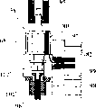
Fig. 1 is the profile along actuating motor rotating shaft among the present invention.
Fig. 2 is the profile along Fig. 1 Vertical Centre Line 2-2.
Fig. 3 is the profile along Fig. 1 Vertical Centre Line 3-3, and shown is the layout of the brush carrier of motor.
Fig. 4 is the expanded view of the winding pattern of a coil.
Shown in Figure 5 is the end-view of armature among Fig. 2, on this armature around wind.
View and Fig. 5 shown in Figure 6 are equidirectional, but wind has been carried out more detailed displaying.
Fig. 7 is the end view of wind among Fig. 6.
Fig. 8 is the local vertical view that amplifies of wind.
Fig. 9 is the sectional view by device part shown in Figure 8.
Figure 10 and Fig. 4 part are similar, but shown be the winding pattern.
Figure 11 is the perspective view of winding pattern.
Figure 12 (1), 12 (2), 12 (3) show wind from Figure 11 mid point A to a B motion process in step (1), (2), the position in (3).
Figure 12 (4), 12 (5), 12 (6) show step among Figure 11 (4), (5), shown in (6) from a B to a C then to the motion process of a D, the position of wind.
Accompanying drawing 12 (7), 12 (8), 12 (9) show step among Figure 11 (7), (8), shown in (9) from a D to an E then to the motion process of a F, the position of wind.
Accompanying drawing 12 (10), 12 (11), 12 (12) show step among Figure 11 (10), the motion shown in (11) and (12) from an A to a D, the position of wind.
Accompanying drawing 12 (13), 12 (14), 12 (15) show step among Figure 11 (13), shown in (14) and (15) from a some D to a C again to the motion process of a F, the position of wind.
Accompanying drawing 13 to 23 is in each winding step, the end view in the part shown in the wind profile.
Embodiment
Be described in detail below with reference to accompanying drawings.At first with reference to accompanying drawing 1-3, the engine starting motor is by Reference numeral 51 expressions, and the engine starting motor is by shown in the embodiments of the invention, although to its special should releasing as understanding, but to one skilled in the art, be easy to it is applied on the electric rotating machine of other types.
Actuating motor 51 is made up of a shell, and by mark 52 expressions, shell comprises a cylindrical yoke, by mark 53 statements.Yoke 53 has a cylinder-shaped sleeve 54, on the inner surface of cylinder-shaped sleeve 54, is stained with a plurality of permanent magnets of separating along circumference 55.In this embodiment, four such permanent magnets are arranged, and be alternately distributed by circumferencial direction.Mode preferably, these permanent magnets 55 are made by the material that neodymium etc. has high magnetic energy.
Shell 52 is made up of front end housing 56 and rear end cap 57, and rear end cap 57 sticks to yoke axle sleeve 54 ends in suitable mode, thereby limits an enclosure space, and in this closed interval, rotor is labeled as 58 to rotor with the form of armature, and rotor is guided by pivot.One fixed mount 59 is arranged, so that annex is fixed on the body of related engine on the rear end cap 57.
Rotor or armature 58 comprise armature shaft 61, and its front end has steering mechanism 62, and this steering mechanism 62 interrelates with steering mechanism on the relevant internal combustion engine flywheel.Rear end cap 57 has a jag, and an O shape annular seal ring 63 is wherein arranged, thereby realizes the excellent sealing to steering mechanism.The end of armature shaft 61 is used as axle journal by ball-and-roller bearing 64 in end cap 57.Oil-sealing arrangement 65 is close to layout with the rear portion of bearing 64.In the similar mode of another kind, armature shaft 61 ends end cap 57 with ball-and-roller bearing 66 in be used as and make axle journal.
Do not twine the method that magnetic pole tooth 68 forms single coil although in Fig. 1-3, be shown specifically, will carry out simple description to it here.The winding end is connected to a rectifier by the method for describing below, is labeled as 73, more clearly, is connected on the contact chip 74 of rectifier 73.
With reference to accompanying drawing 3, brush 75 is supported by brush carriage 76, and support 76 is installed on rectifier plate or the brush carriage 77.Brush 75 engages with rectifier slide plate 74 by spring 78.
Electric current is switched on to winding by the terminal box 79 on the rear end cap 57.Electric current flows to brush 75 from terminals 81.Such circuit arrangement is the known technology of this area, therefore no longer describes in detail.Equally, because the common structure of actuating motor 51 also is the known technology of this area, thereby except the method for coil windings, also no longer describe in detail.
The formation method and apparatus of coil windings will be described below.At first, the method for winding single coil 4 is described with reference to the accompanying drawings.When forming coil, lead 80 forms a circle coil around every group of magnetic pole tooth 68 of given number (for example being 4) around two circles.Coil in every group of four magnetic pole tooth is by changing the winding starting point in tooth and forming continuously.
For this reason, as shown in Figure 4, the starting point of the lead 80 of every circle coil is fastened on the rectifier slide plate 74 of a tooth of two teeth 68 in the middle of four magnetic pole tooths, and terminal point then is fastened on another rectifier slide plate 74.Terminal rectifier slide plate 74 forms the starting point of next coil.Like this, lead 80 is fastened on the rectifier slide plate corresponding to magnetic pole tooth 68, and the rectifier slide plate is positioned at the center of the magnetic pole tooth that is twining lead 80 68 of given number.Therefore, coil is to be entwined by two oblique lead-in wires of rectifier slide plate of 80 leads from starting point and terminal point.The canoe of lead 80 constantly repeats (or twining simultaneously).Every circle coil twines every group of 4 magnetic pole tooths 68, and the corresponding rectifier slide plate 74 of coil forms continuously.
In winding process, when using a heavy gauge wire (diameter is 1 millimeter or bigger), nozzle is supplied with lead, and lead around two circles, as shown in the figure, in the lead lead-ingroove, forms coil thereby twine magnetic pole tooth in the groove outside.Among the present invention, have corresponding and the same number of nozzle, be distributed in the outside of iron core circumference, form from iron core 67 outer circumferential sides simultaneously with magnetic pole tooth 68 coils corresponding and that quantity is identical with the magnet radial poles tooth.
Fig. 5 is a schematic diagram of carrying out the wind of aforementioned winding action among the present invention, comprises a rotor.Know that wire casing 71 is formed between armature 67 magnetic pole tooth 68 radially.Nozzle ring 82 is installed around corresponding armature 67.Nozzle ring 82 has a plurality of and quantity (among the figure being 14) respective nozzles 83 groove 71, that is, the quantity of the quantity of 83 nozzles and groove 71 as many.
Each nozzle 83 radially passes nozzle ring 82.The end of the inner peripheral surface of nozzle 83 constitutes the outlet of lead 80, makes chamfering or circle around the corner, so that the insulating barrier of guardwire.Lead is supplied with from nozzle 83, in wire casing inlet insertion wire casing 71 separately.
Then, nozzle ring 82 and iron core 67 arbitrary or both rotation and axial motions make each nozzle make shuttling movement with respect to magnetic pole tooth 68, form coil thereby lead twines magnetic pole tooth.This motion will be described in more detail with reference to Figure 10 below.
Shown in Fig. 6 and 7, in this embodiment, nozzle ring 82 has 21 nozzles 83, and each nozzle is separately corresponding to 21 grooves 71 of armature 67.Nozzle bore 83 radially passes nozzle ring 82, and in periphery very big diameter parts is arranged, and forms nozzle guide hole 84 (Fig. 6) above.Guide hole 84 is used for guiding the lead of insertion, and owing to its major diameter can easily be inserted lead.Lead 80 passes guide hole 84, and inserts corresponding wire casing 71, and the given length of lead is corresponding to the length of coil.
Referring now to Fig. 8 and 9, nozzle ring 82 is installed on the rotatable rotating disk 85.Conduit 86 is on the rotating disk 85 in nozzle bore 83 outsides.Every conduit 86 forms at its radial outer end, at upside a kerf 87 is arranged, and stopper 88 pivotally is installed on the axle 89 of each otch 87.Stopper 88 is used for preventing that the lead that inserts in the conduit 86 from skidding off.
Referring now to accompanying drawing 10 and 11 winding pattern and method are described.As shown in drawings, when on 4 magnetic pole tooths 68, twining lead, nozzle bore 83 along specified path from A → B → C → D → E → F → A makes shuttling movement.That is, nozzle is crossed a tooth 68 along wire casing inlet 72 from position A to position B, crosses groove inlet 72 along circumference then and moves to position C, and position C is at the end of the magnetic pole tooth group that is wound.Nozzle return back to the inlet 72 position D of groove end then.
Then, nozzle 83 enspheres mouthfuls 72 along the line and crosses other coil inlet 72 and turn back to position E, and nozzle 83 is crossed initial wire casing inlet 72 to position F along circumference then, turns back to position A along the coil end again.The nozzle repeating motion, then lead forms a coil again around magnetic pole tooth 68.
Accompanying drawing 12 (1) to 12 (15) illustrates in greater detail the actual location of nozzle ring 82 and armature 58 in running.These Reference numerals are corresponding to the point of mark in the accompanying drawing 11.Only set forth the motion of a nozzle bore 83 in these accompanying drawings, but obviously, in winding process, each nozzle bore 83 moves in mode similarly simultaneously.
Referring now to the secondary accompanying drawing among Figure 12 these motions are described:
Figure 12 (1), lead 80 ends are clamped and are pulled out from nozzle bore 83 by clamp device (not shown).
Figure 12 (2), the lead 80 in the nozzle ring 82 is clamped, along drawing on the direction of arrow a.
Figure 12 (3) draws on the nozzle ring 82 and suspends one section, and armature spindle 61 is around the direction rotation of arrow b, and lead 80 ends are fixed, and the end that makes lead 80 is along circumferential backlash.Along with the skew of wire end, lead 80 ends are pushed in the groove (not shown) of rectifier 73 upper conductor standing parts 92 by blade drive cylinder 91.Like this, as shown in Figure 4, corresponding to the groove inlet skew along the circumferential direction of the contact chip 74 of coil starting point.
Figure 12 (4), then, nozzle ring is crossed end winding and is risen to B point among Figure 11.
Figure 12 (5), when nozzle ring 82 descends along arrow c direction, armature spindle 61 is along the rotation of arrow d direction, and nozzle ring is moved to C point among Figure 11, this circumference excess of stroke.
Figure 12 (6), armature spindle 61 along with Figure 12 (5) in opposite direction (direction shown in the arrow e) rotation, thereby the C point of nozzle from Figure 11 moves to the D point, this point enters the mouth 71 corresponding to next wire casing.
Figure 12 (7), nozzle ring 82 drops to E point among Figure 11 along the direction of arrow f, and this point has exceeded the below of coil end.
Figure 12 (8), nozzle ring 82 rises along the direction of arrow g, thereby returns the part that exceeds downwards, and armature spindle 61 is along the direction rotation of arrow h, and drive nozzle bore 83 moves to the F point among Figure 11, and this circumference direction has exceeded the position of initial wire casing.
Figure 12 (9), armature spindle 61 returns to the A point along the direction rotation of arrow i with the F point of nozzle bore 83 from Figure 11.Like this, the coil winding work of first circle has just been finished.
Figure 12 (10), the step shown in accompanying drawing 12 (4), nozzle ring 82 rises along the direction of arrow j, thereby begins to twine the second circle coil, and nozzle bore 83 moves to the B point, and this point is the excess of stroke upwards.
Figure 12 (11), the step shown in accompanying drawing 12 (5) along arrow k decline nozzle ring 82, thereby is return the stroke that exceeds, and simultaneously, armature spindle 61 moves to the C point along the direction rotation of arrow I with nozzle bore 83, and this puts the excess of stroke along the circumferential direction.
Figure 12 (12), the step armature spindle 61 shown in accompanying drawing 12 (6) be along the rotation of the direction of arrow m, thus return exceed journey, nozzle moves to the D point.
Figure 12 (13), as the step of accompanying drawing 12 (7), nozzle ring 82 descends along the direction of arrow n, and the excess of stroke moves to the E point downwards.
Figure 12 (14), nozzle ring 82 further reduce, and the terminal of the lead 80 of given length (this example is the length of 2 circles) is exposed from nozzle bore 83.
Figure 12 (15), the lead terminal is pushed by blade drive cylinder 91 in the groove (not shown) in the lead fixed part 92 of rectifier 73 and fixes.The groove at the groove adjacent conductor top of lead 80 terminals.
Then, the wire end that stretches out downwards from lead fixed part 92 is partly pruned, pounded the limit, lead starting point and terminal point are sticked on the standing part 92 by heat.
Like this, the coil that a circle two changes is at magnetic pole tooth, and for example 4 magnetic pole tooths (Figure 10) are gone up and formed.Like this, utilize aforementioned nozzle ring 82 (accompanying drawing 5 and 6) simultaneously, form and all magnetic pole tooth respective coil, simultaneously, in the forming process of a coil, form all coils.
Figure 13-the 23rd, more detailed method and apparatus schematic diagram progressively illustrates according to winding working procedure of the present invention.
As Figure 13, by carriage 93, for example the armature 58 of handling machinery hand rest is wound device 94 and is transported to the wind top, and the chuck 95 that the upper end of armature spindle 61 is wound on the device blocks.Wind 94 has a clamp 96 fixed armatures 58, go up moving vane 97, go up the following moving vane of nozzle ring 82, fixed blade 98 and nozzle ring 82 belows of the below of moving vane 97.
But clamp 96 is with respect to base 101 vertical moving, with fixed armature 58.Many guide vanes 102 to groove inlet 72 on the radially corresponding armature 58 are arranged, the corresponding inlet of a pair of blade on the base 101.
In the breach that last moving vane 97 inserts between the guide vane 102, and in the lead 80 propelling grooves 71.For this reason, lead 80 passes nozzle ring 83, and the tip of lead contacts with clamp 96 or be close.At this moment, as shown in figure 13, lead 80 passes a pair of guide vane.
Then, as shown in figure 14, armature 58 is deviate from (Figure 13) from carriage 93, is blocked by chuck 95, descends and is placed on the base 101.Then, clamp 96 descends along the direction of arrow p, with the end of clamping wire 102.
Then, as shown in figure 15, armature 58 descends (or moving vane 99,97, fixed blade 98 and nozzle bore 83 rise), makes lead begin moving upwards.Lead 80 rises, and places between the guide vane 102.
Then, as shown in figure 16, by the end of the lead 80 of clamp 96 clampings, deviate from the stroke that lead 80 is making progress, the stroke that makes progress stops the end time.Then, guide vane 102 relative armatures 58 are along the rotation of the direction of arrow q, reverse the initiating terminal step of corresponding Figure 12 (3) (this move) of lead 80.Along with slightly reversing of lead 80, following moving vane 99 moves along the direction of arrow r, and the initiating terminal of lead 80 is by the breach between the baffler 102, be pushed into lead fixed part 92 in the rectifier 73 groove in (not shown).
Then, as shown in figure 17, nozzle bore 83 rises (or armature 58 descends), and lead 80 is stretched.
Figure 18 shows armature 58, by shown in Figure 10 and 11, given number of times axially and the repeating to twine and move of the excess of stroke reciprocation cycle of circumferential, on armature 58, lead 80 is wound into magnetic pole tooth 68.
After finishing winding, armature 58 is removed from wind, used carriage 93 (Figure 13) to support again, as shown in figure 19, be sent to another wind 103.Spacer 104 moves along the direction of arrow s, enters the wire casing 72 inlet (not shown) of iron core, to locate in direction of rotation.
Then, as shown in figure 20, moving vane 105 is made up of blade many, advances near the position of the lead fixed part 92 of rectifier 73 along the direction of arrow t, and the end of lead 80 is sandwiched between the blade.
Then, as shown in figure 21, armature 58 is along the direction rotation of arrow u, and lead 80 ends along the circumferential direction reverse, and as shown in Figure 4, the purpose of this operation is the offset wires end, with connection contact chip 74.As a result, the end of lead 80 is towards the groove of lead fixed part, and is adjacent with the lead initiating terminal.
Then, as shown in figure 22, propulsion blade 106 advances along the gap that the direction of arrow v is passed moving vane 105, and the end of lead 80 is advanced in the lead fixed groove partly of rectifier 73.
Then, as shown in figure 23, armature 58 drops near the cutter 107 that places wind 103 belows.Cutter 107 advances along the direction of arrow w, and the end that wire end stretches out from the lead constraint portions is sheared.
According to the above, in a shuttling movement of nozzle, nozzle has surpassed end winding, for example, and at axial upward stroke end; For example, the nozzle circular motion is by excess of stroke reversion; Nozzle surpasses given position or groove inlet at the circumference end of travel; After the circumference reversion, nozzle is transformed into axially to down stroke.Like this, nozzle begins next stroke then in axial and the circumference end of travel excess of stroke when revolution or after the backhaul, thereby conductor length has surplus, can realize level and smooth winding, on magnetic pole tooth, not need nozzle is inserted in the wire casing during winding around, but lead is inserted in the wire casing.Especially, because the reversion then of the nozzle circumference excess of stroke, the tension force of the lead that winding around applies at the edge of iron core when terminal is released, and this can prevent that the end winding height is inconsistent, or because the irregular winding that the variation of tension force produces is shaped coil-end stable and uniform ground.Certainly, the description of front is a preferred version of the present invention, not departing from as the situation of the spirit and scope of the present invention that limit in the claims under, can make multiple changes and improvements.
Claims (20)
1. the winding method of a rotary motor armature, a plurality of magnetic pole tooths that radially extend are arranged on the magnetic core of electric rotating machine, magnetic pole tooth is spaced in a circumferential direction, between adjacent magnetic pole tooth, form groove, said method comprising the steps of: in the lead lead-ingroove, move one lead around at least one magnetic pole tooth circulation, with the magnetic pole tooth nozzle on the magnetic core outer circumferential sides, forming the circulation of continuous coil moves and comprises following motion, when the circumference of magnetic pole tooth is noted first groove, move forward to the another side of pivot from a side continuous axial of pivot, circumference on the opposite side of pivot magnetic pole tooth travels forward and notes second groove, the axial side of gyration from the opposite side of pivot to pivot, circumgyration moves to first groove, at least one circular motion runs through in each groove that is write down, and returns wherein so that the wire relaxes of twining.
2. the winding method of armature as claimed in claim 1 is characterized in that, at least one circular motion, an axial location of lead changes.
3. the winding method of armature as claimed in claim 2 is characterized in that, in two circular motion, the axial location of lead changes.
4. the winding method of armature as claimed in claim 1 is characterized in that, two circular motion all run through in each groove that is write down, and returns wherein so that the wire relaxes of twining.。
5. the winding method of armature as claimed in claim 4 is characterized in that, at least one circular motion, the axial location of lead changes.
6. the winding method of armature as claimed in claim 5 is characterized in that, in two circular motion, the axial location of lead changes.
7. the winding method of armature as claimed in claim 1 is characterized in that, a plurality of adjacent magnetic pole tooths by identical loop institute around.
8. the winding method of armature as claimed in claim 7 is characterized in that, at least one circular motion, the axial location of lead changes.
9. the winding method of armature as claimed in claim 8 is characterized in that, in two circular motion, the axial location of lead changes.
10. the winding method of armature as claimed in claim 7 is characterized in that, two circular motion all run through in each groove that is write down, and returns wherein so that the wire relaxes of twining.
11. the winding method of armature as claimed in claim 10 is characterized in that, at least one circular motion, the axial location of lead changes.
12. the winding method of armature as claimed in claim 11 is characterized in that, in two circular motion, the axial location of lead changes.
13. the winding method of armature as claimed in claim 1 is characterized in that, forms a plurality of loops around different magnetic pole tooths simultaneously.
14. the winding method of armature as claimed in claim 13 is characterized in that, at least one circular motion, the axial location of lead changes.
15. the winding method of armature as claimed in claim 14 is characterized in that, in two circular motion, the axial location of lead changes.
16. the winding method of armature as claimed in claim 13 is characterized in that, two circular motion all run through in each groove that is write down, and return wherein so that the wire relaxes of twining.
17. the winding method of armature as claimed in claim 16 is characterized in that, at least one circular motion, the axial location of lead changes.
18. the winding method of armature as claimed in claim 17 is characterized in that, in two circular motion, the axial location of lead changes.
19. wind that on the armature magnetic pole that radially extends, twines many group coils simultaneously, comprise, one has the ring-type needle ring that cooperates armature shape, a plurality of pin holes radially pass needle ring, to transmit the many leads that twine magnetic pole tooth, a driver is realized relative rotation and axial motion between described needle ring and pivot, to center on magnetic pole tooth winding lead.
20. the winding method of armature as claimed in claim 19 is characterized in that, the quantity of acicular pores equals the quantity in space between the armature magnetic pole.
Applications Claiming Priority (4)
| Application Number | Priority Date | Filing Date | Title |
|---|---|---|---|
| JP2001271207A JP2003088064A (en) | 2001-09-07 | 2001-09-07 | Winding method of armature of electric rotating machine, and its equipment |
| JP2001-271207 | 2001-09-07 | ||
| US10/064,923 US6749145B2 (en) | 2001-09-07 | 2002-08-29 | Winding method and device for an armature for rotary electric machines |
| US10/064923 | 2002-08-29 |
Publications (1)
| Publication Number | Publication Date |
|---|---|
| CN1414688A true CN1414688A (en) | 2003-04-30 |
Family
ID=19096745
Family Applications (1)
| Application Number | Title | Priority Date | Filing Date |
|---|---|---|---|
| CN02143457.3A Pending CN1414688A (en) | 2001-09-07 | 2002-09-09 | Winding method and device for armature in electric rotating machine |
Country Status (5)
| Country | Link |
|---|---|
| US (1) | US6749145B2 (en) |
| EP (1) | EP1294083A3 (en) |
| JP (1) | JP2003088064A (en) |
| CN (1) | CN1414688A (en) |
| TW (1) | TW578355B (en) |
Cited By (2)
| Publication number | Priority date | Publication date | Assignee | Title |
|---|---|---|---|---|
| CN101965673A (en) * | 2008-02-27 | 2011-02-02 | 阿拓普股份公司 | Apparatus and method for winding and terminating cores of dynamoelectric machines |
| CN101860145B (en) * | 2010-05-13 | 2012-08-29 | 崔建伟 | Winding device and winding method of motor armature of electric motor vehicle |
Families Citing this family (5)
| Publication number | Priority date | Publication date | Assignee | Title |
|---|---|---|---|---|
| US8357242B2 (en) * | 2007-05-03 | 2013-01-22 | Jewett Russell F | Crystalline film devices, apparatuses for and methods of fabrication |
| JP4285559B2 (en) * | 2007-04-26 | 2009-06-24 | 株式会社デンソー | Rotor winding device and rotor manufacturing method |
| JP4905538B2 (en) * | 2009-11-05 | 2012-03-28 | 株式会社デンソー | Rotor winding device |
| JP6173093B2 (en) | 2013-07-28 | 2017-08-02 | 日特エンジニアリング株式会社 | Winding device and winding method |
| DE102014111509A1 (en) * | 2014-08-12 | 2016-02-18 | Valeo Systèmes d'Essuyage | commutator |
Family Cites Families (9)
| Publication number | Priority date | Publication date | Assignee | Title |
|---|---|---|---|---|
| US2714174A (en) * | 1951-06-23 | 1955-07-26 | Cleveland Electrical Equipment | Armatures for electric generators, motors and the like |
| DE1025502B (en) * | 1955-09-28 | 1958-03-06 | Fiat Spa | Machine for winding conductors on rotating armatures of electrical machines |
| SE8604226D0 (en) * | 1986-10-06 | 1986-10-06 | Roland Holm | PROCEDURE AND DEVICE FOR WINDING OF ROTOR |
| NL8902180A (en) * | 1989-08-29 | 1991-03-18 | Philips Nv | METHOD FOR DEVELOPING AN ANCHOR BODY FROM AN ANCHOR AND ELECTRICAL MACHINE EQUIPPED WITH AN ANCHOR MADE ACCORDING TO THE METHOD |
| JPH04197054A (en) * | 1990-11-28 | 1992-07-16 | Mabuchi Motor Co Ltd | Armature winding method for miniature motor |
| US5413289A (en) * | 1991-07-30 | 1995-05-09 | Axis Usa, Inc. | Programmably controlled armature winding apparatus |
| CA2193461A1 (en) * | 1995-12-20 | 1997-06-21 | Patrick A. Dolgas | Stator winding method and apparatus |
| GB2328892B (en) * | 1997-09-04 | 1999-12-15 | Honda Motor Co Ltd | Winding method and winding apparatus for producing stators for electric motors |
| JPH11164533A (en) * | 1997-11-25 | 1999-06-18 | Asmo Co Ltd | Motor, armature and its coil winding method |
-
2001
- 2001-09-07 JP JP2001271207A patent/JP2003088064A/en active Pending
-
2002
- 2002-08-29 US US10/064,923 patent/US6749145B2/en not_active Expired - Fee Related
- 2002-09-05 EP EP02019986A patent/EP1294083A3/en not_active Withdrawn
- 2002-09-09 CN CN02143457.3A patent/CN1414688A/en active Pending
- 2002-09-09 TW TW091120452A patent/TW578355B/en not_active IP Right Cessation
Cited By (3)
| Publication number | Priority date | Publication date | Assignee | Title |
|---|---|---|---|---|
| CN101965673A (en) * | 2008-02-27 | 2011-02-02 | 阿拓普股份公司 | Apparatus and method for winding and terminating cores of dynamoelectric machines |
| CN101965673B (en) * | 2008-02-27 | 2013-06-19 | 阿拓普股份公司 | Apparatus and method for winding and terminating cores of dynamoelectric machines |
| CN101860145B (en) * | 2010-05-13 | 2012-08-29 | 崔建伟 | Winding device and winding method of motor armature of electric motor vehicle |
Also Published As
| Publication number | Publication date |
|---|---|
| EP1294083A2 (en) | 2003-03-19 |
| TW578355B (en) | 2004-03-01 |
| US6749145B2 (en) | 2004-06-15 |
| EP1294083A3 (en) | 2004-03-24 |
| US20030047636A1 (en) | 2003-03-13 |
| JP2003088064A (en) | 2003-03-20 |
Similar Documents
| Publication | Publication Date | Title |
|---|---|---|
| CN1194460C (en) | Method and device for coiling motor stator | |
| CN1206676C (en) | Coil winder and winding method | |
| CN1257596C (en) | Winding method and device | |
| US6910654B2 (en) | Apparatus and method for winding multi-layer coil in trapezoidal winding space | |
| CN1149726C (en) | DC electric motor | |
| CN1399391A (en) | Stator winding structure for rotary magnetic field motor and its manufacture | |
| CN1689211A (en) | Permanent magnet machine | |
| CN1976169A (en) | Rotary electric machine with reduced torque ripple | |
| JP2004104870A (en) | Armature for rotating machine and its winding method | |
| CN100340761C (en) | Fuel pump for mounting in fuel tank | |
| CN1414688A (en) | Winding method and device for armature in electric rotating machine | |
| CN1178368C (en) | Motor | |
| CN1409463A (en) | Armature insulator in rotary motor | |
| CN1409467A (en) | Brushless DC motor | |
| JP2011239649A (en) | Manufacturing method of stator coil and motor using the stator coil, and apparatus for manufacturing the stator coil | |
| CN1113449C (en) | Winder for armature-winding and winding method for amature-winding | |
| CN1471222A (en) | Stepping motor | |
| US6148499A (en) | Method and device to draw-in coils into slots of stator laminated cores of electric machines | |
| CN1407697A (en) | Step motor | |
| US4053111A (en) | Apparatus and method for producing distributed stator windings | |
| CN101040420A (en) | Commutator motor and method of manufacturing the same | |
| KR101864075B1 (en) | Coil inserting method into stator for BLDC motor | |
| CN1521919A (en) | Rotary electrical apparatus | |
| CN1465124A (en) | Electromotive mechanism | |
| JP4769378B2 (en) | Winding method, winding machine and multi-pole armature |
Legal Events
| Date | Code | Title | Description |
|---|---|---|---|
| C06 | Publication | ||
| PB01 | Publication | ||
| C10 | Entry into substantive examination | ||
| SE01 | Entry into force of request for substantive examination | ||
| C02 | Deemed withdrawal of patent application after publication (patent law 2001) | ||
| WD01 | Invention patent application deemed withdrawn after publication |